The document provides information about cable tray systems, including:
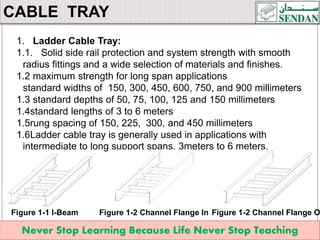
- The six main types of cable trays: ladder, solid bottom, trough, channel, wire mesh, and single rail.
- The materials cable trays can be made from, including steel, aluminum, and fiber reinforced plastic.
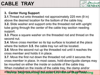
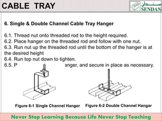
- The steps for installing cable trays, which include marking, cutting, drilling holes, installing supports, and fixing fittings and accessories.
- Common tools used for cable tray installation like saws, drills, wrenches, and levels.
The document is a training manual that outlines cable tray types, materials, and installation procedures.