Downloaded 334 times
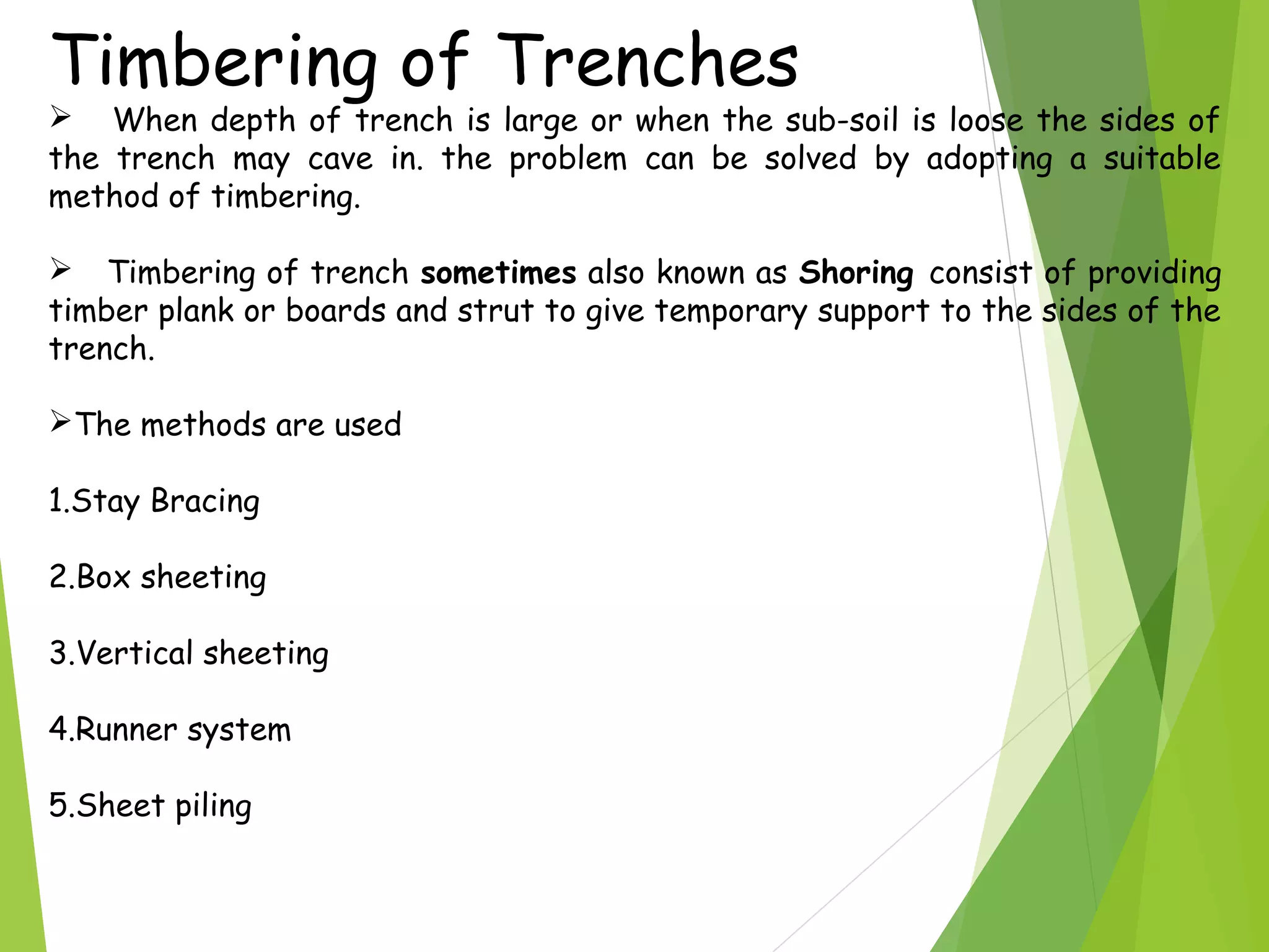
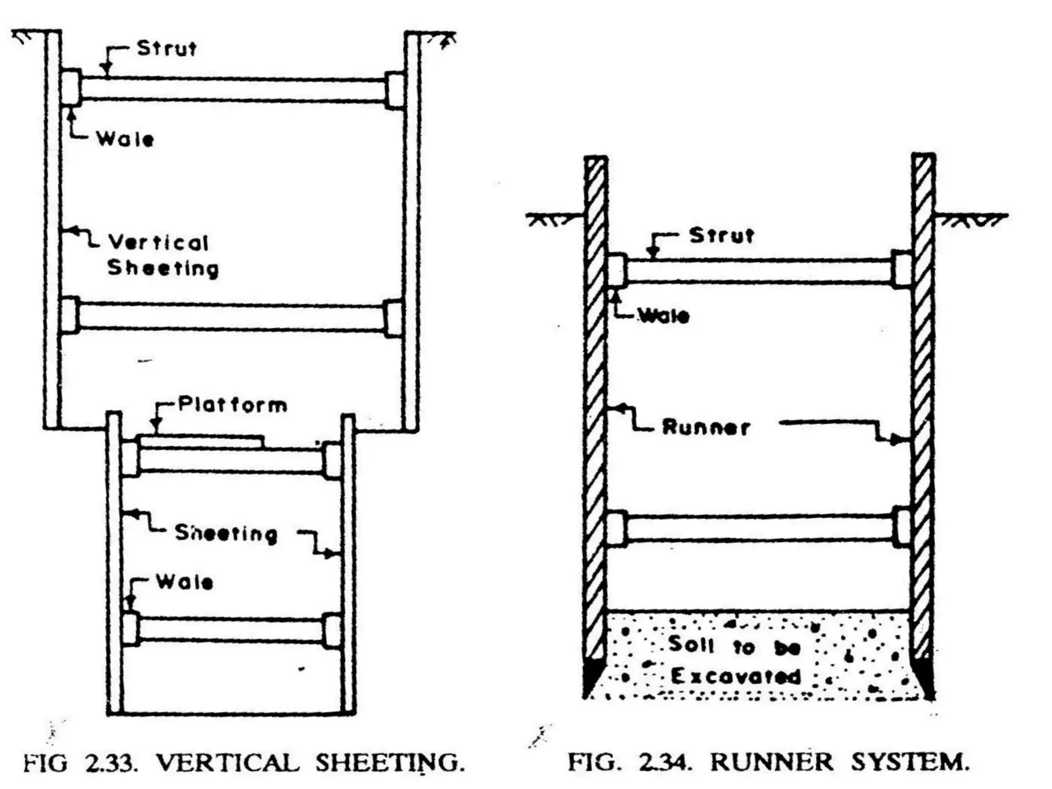
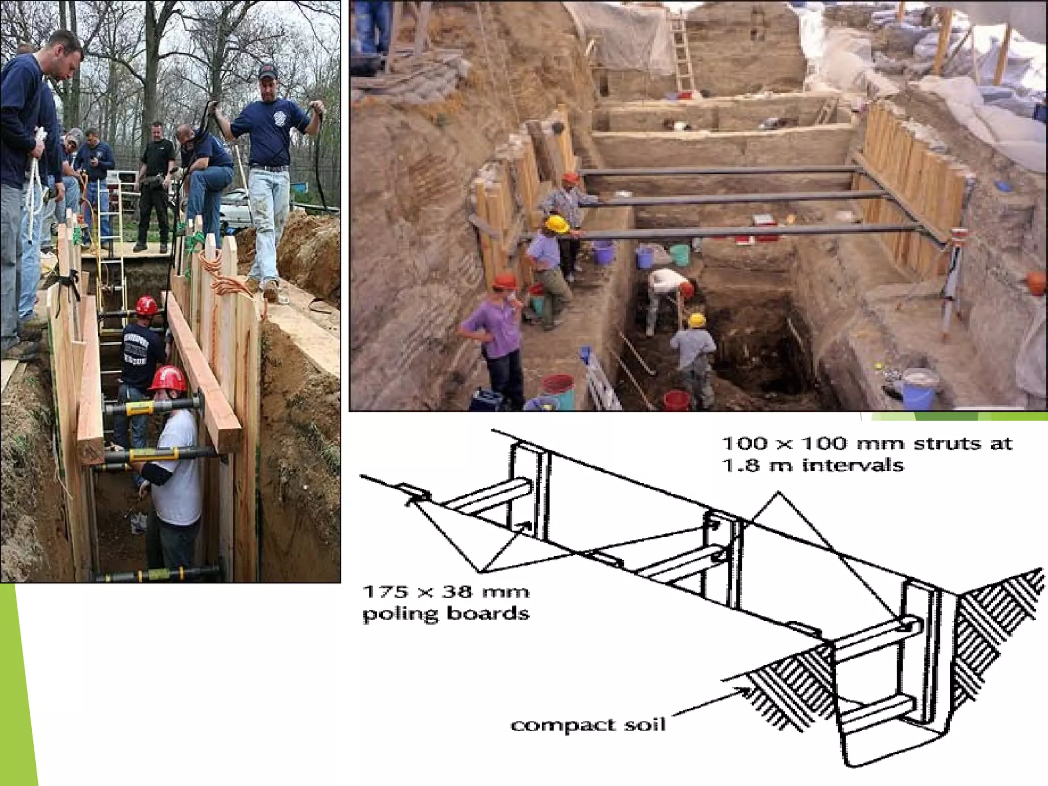
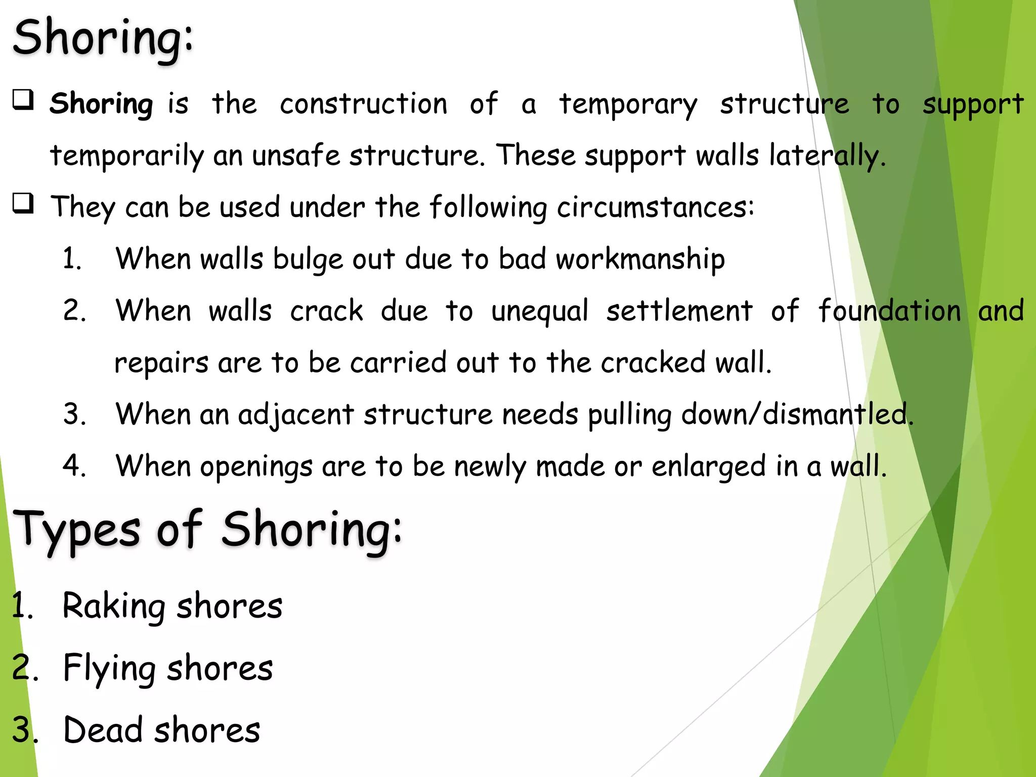
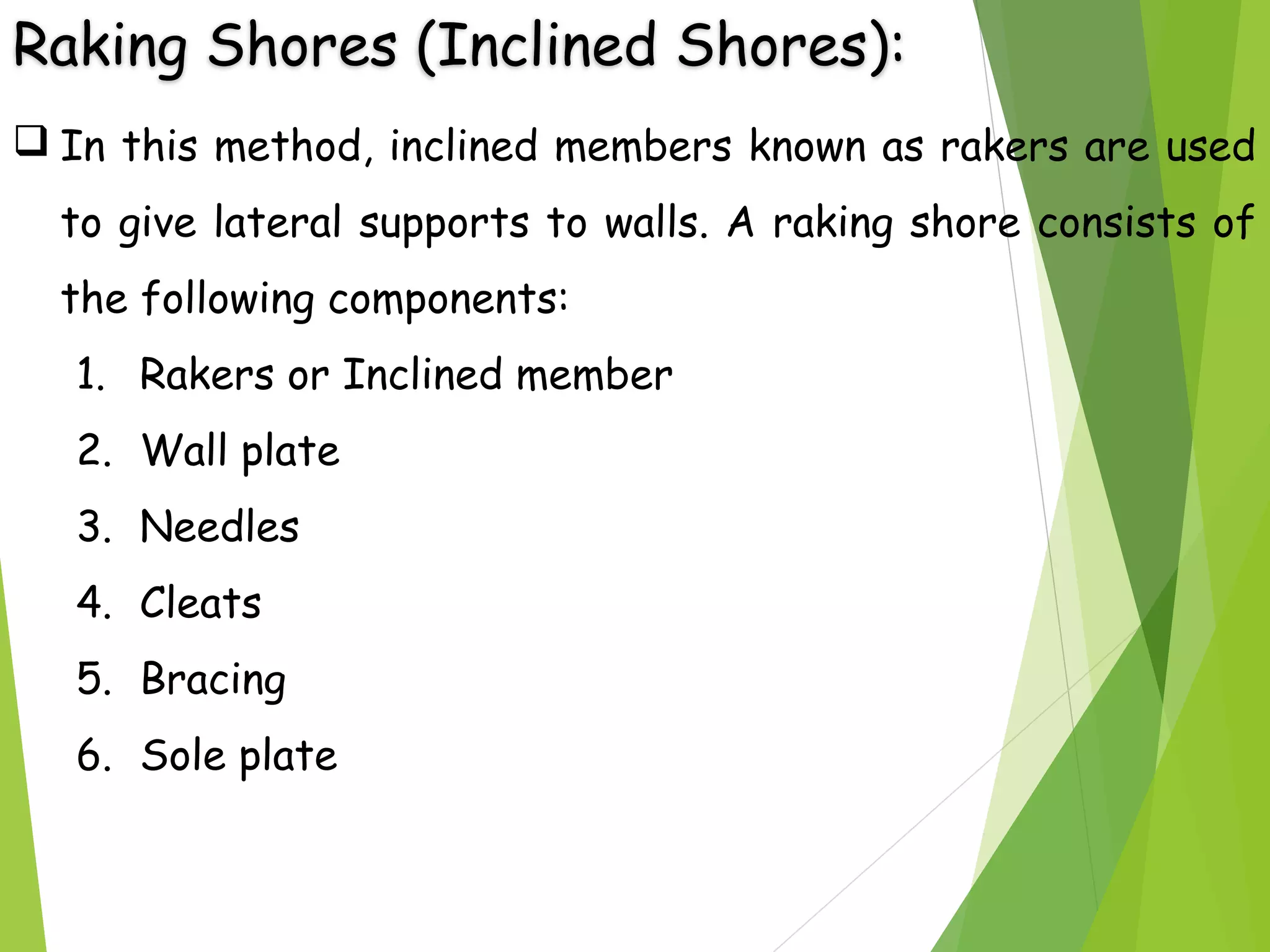
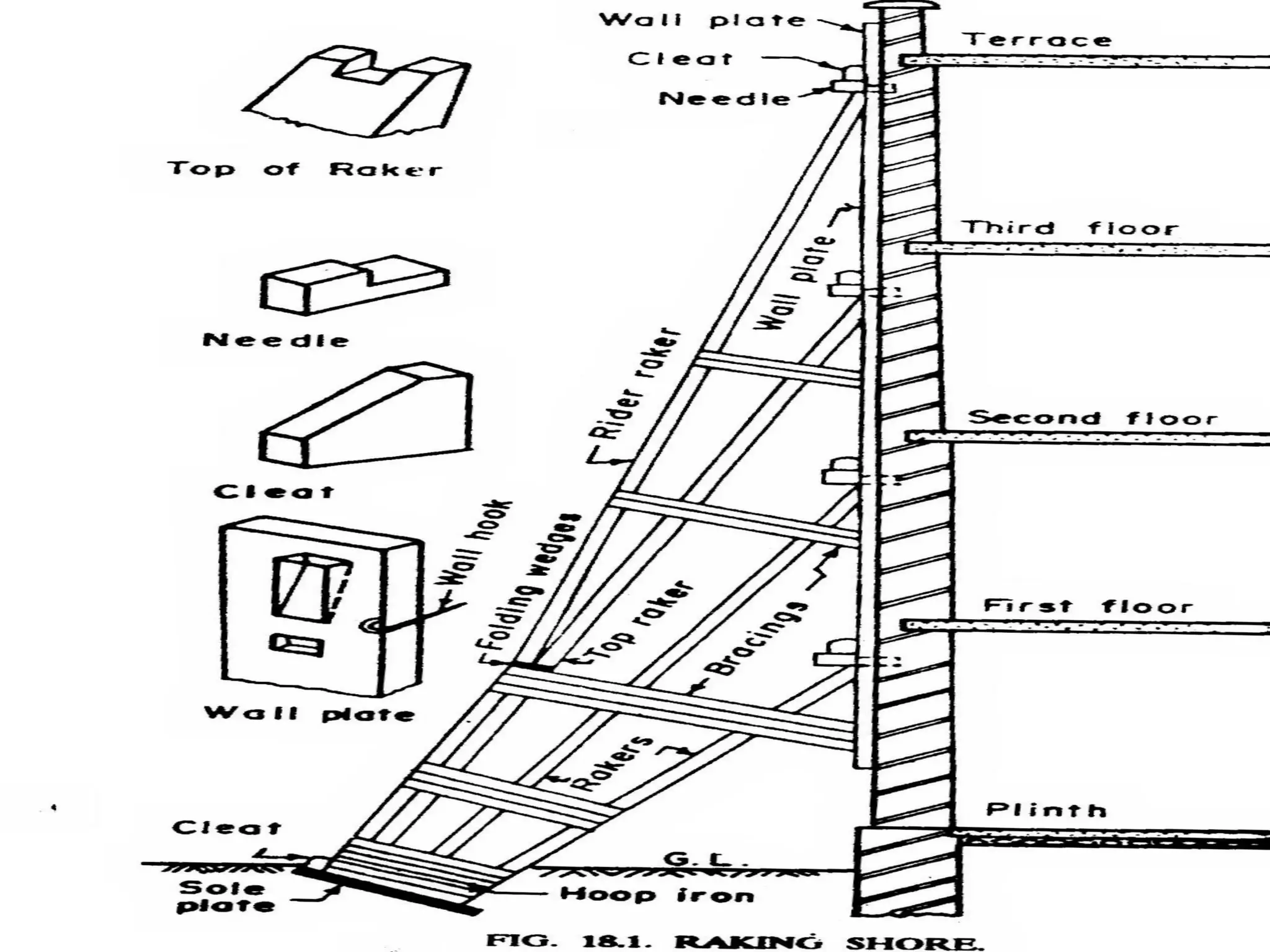
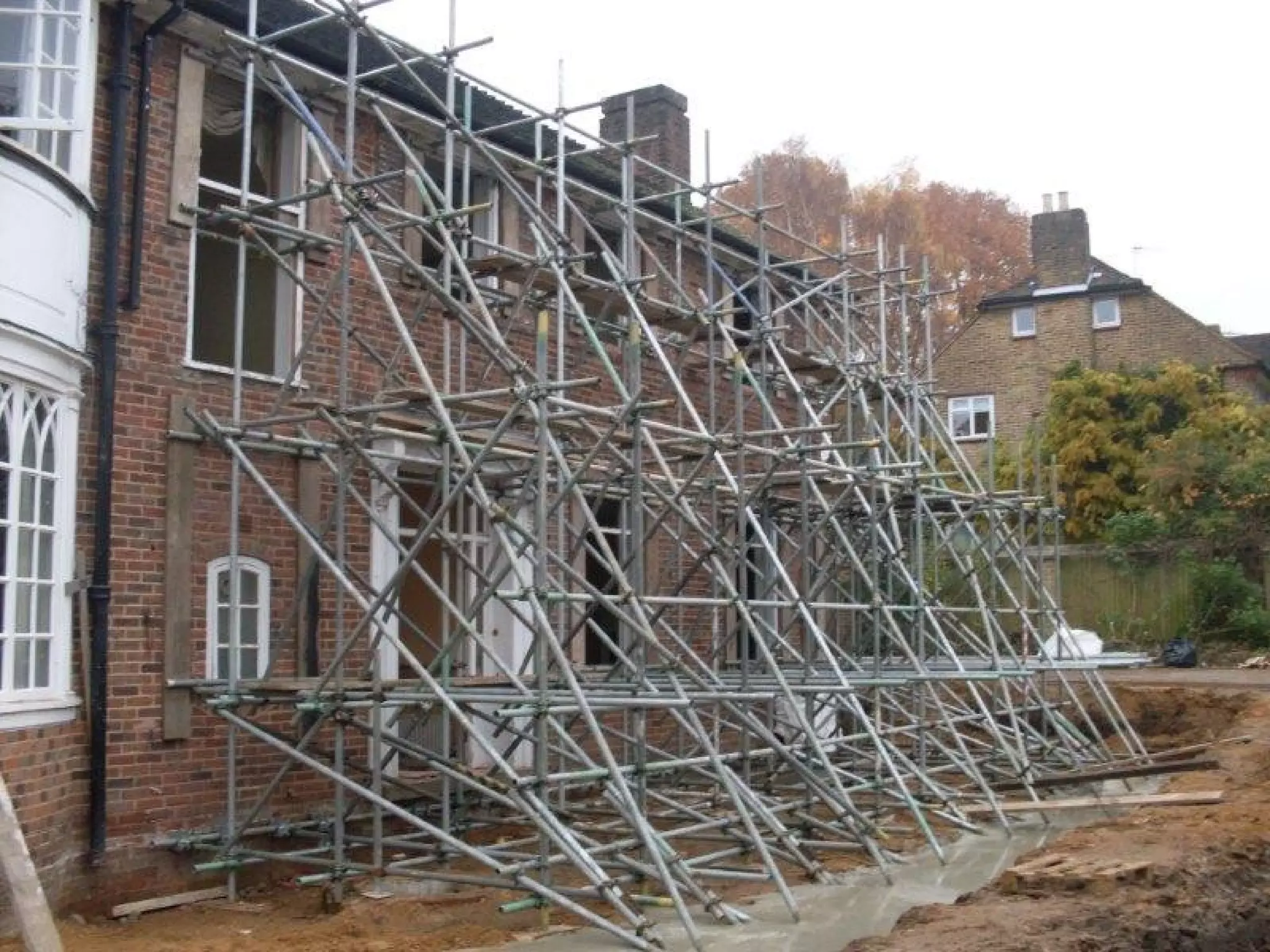
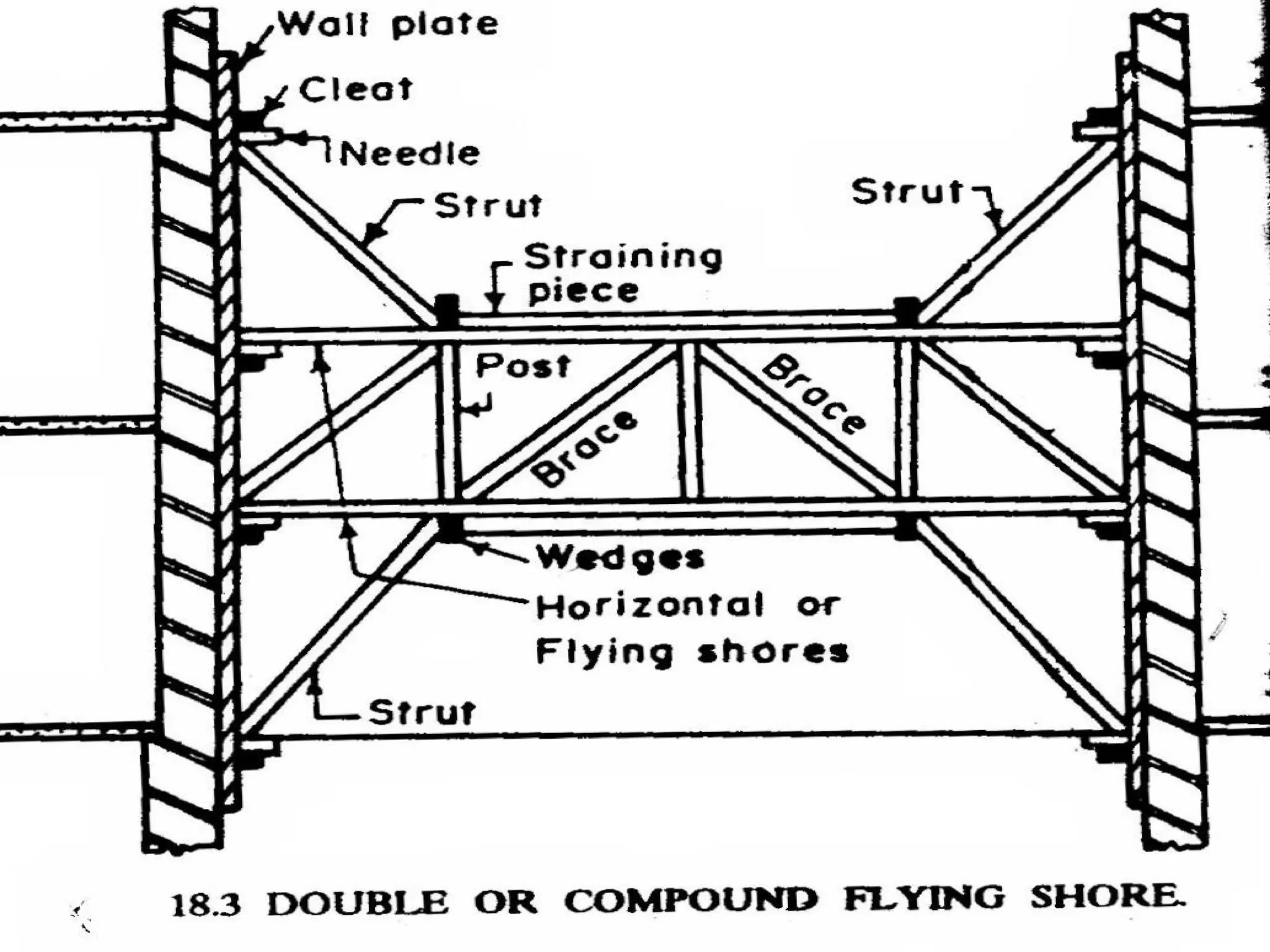
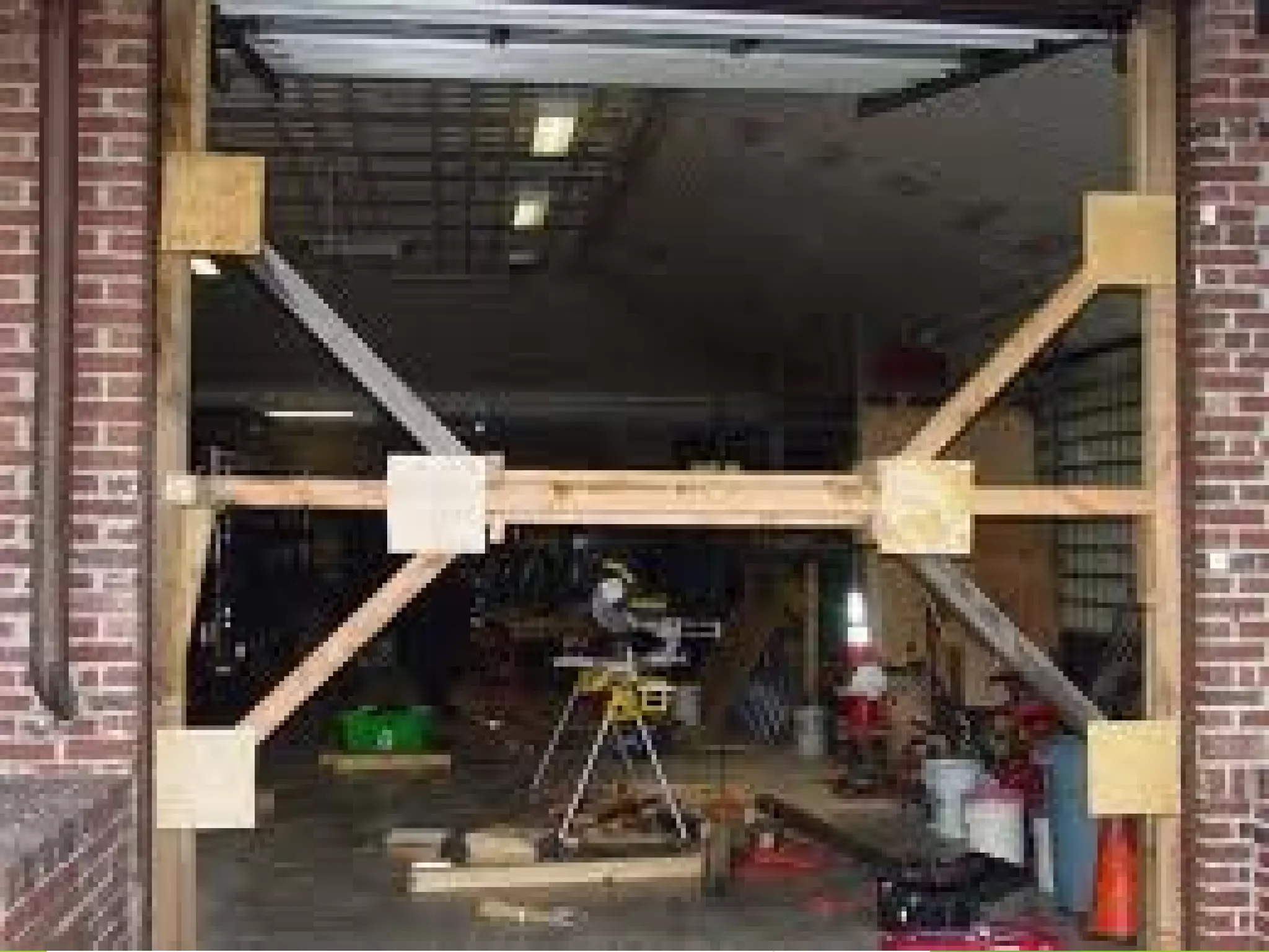
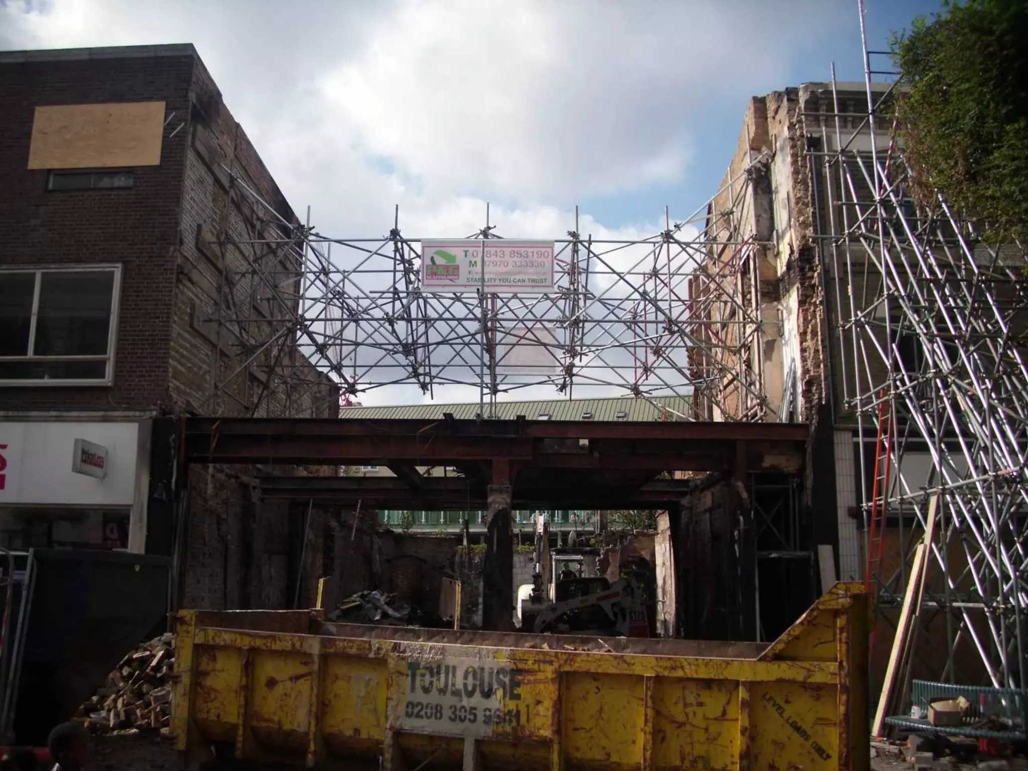
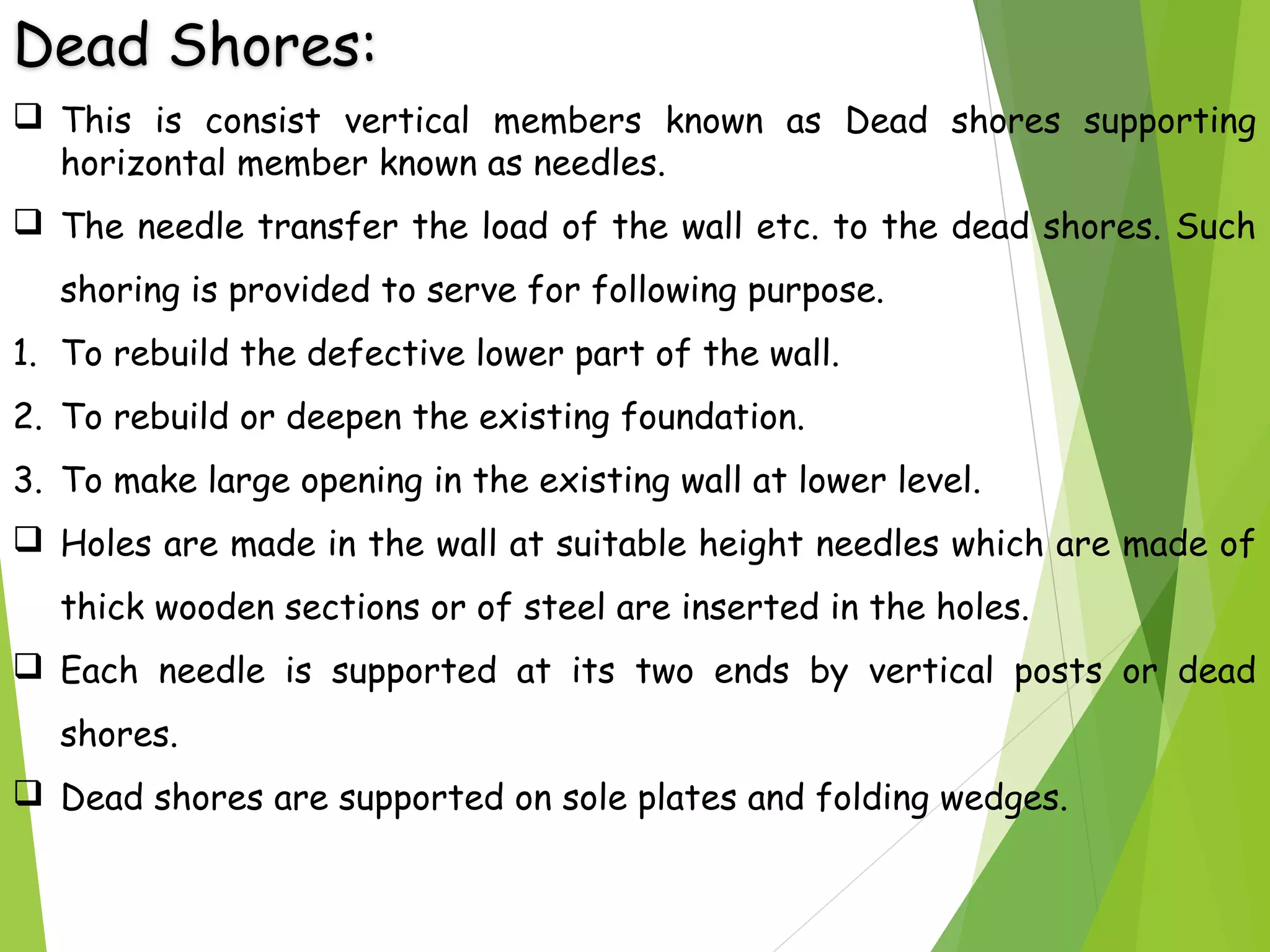
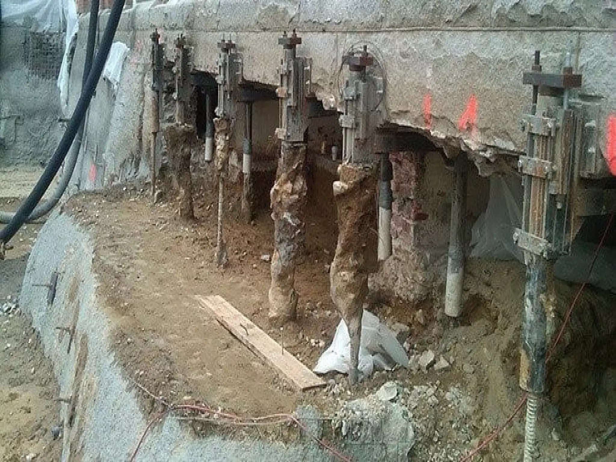
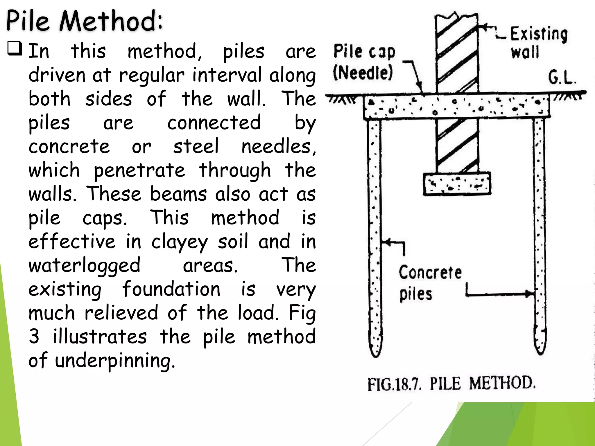
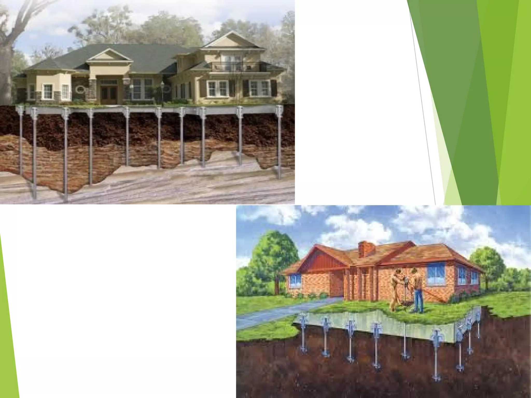
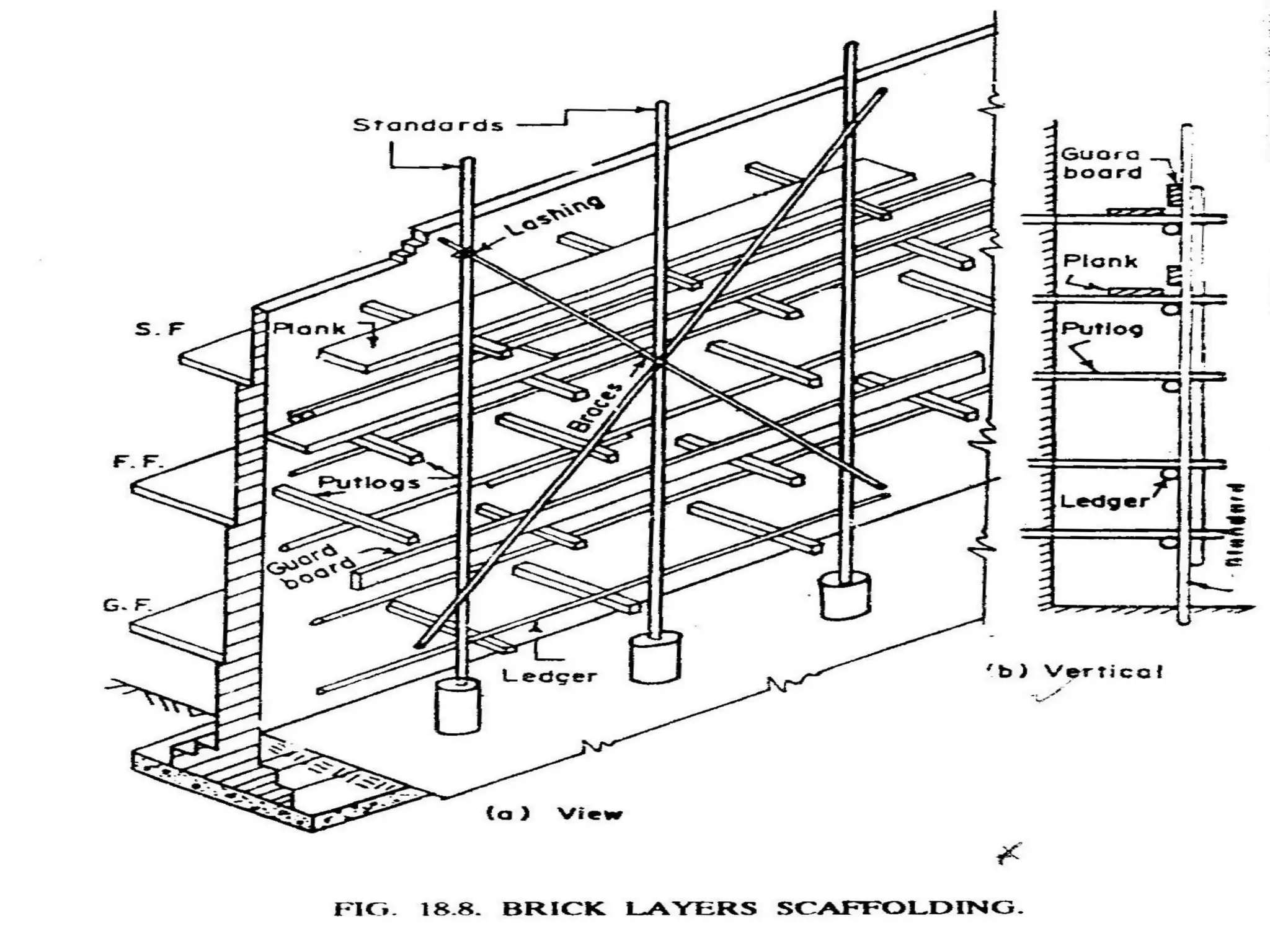
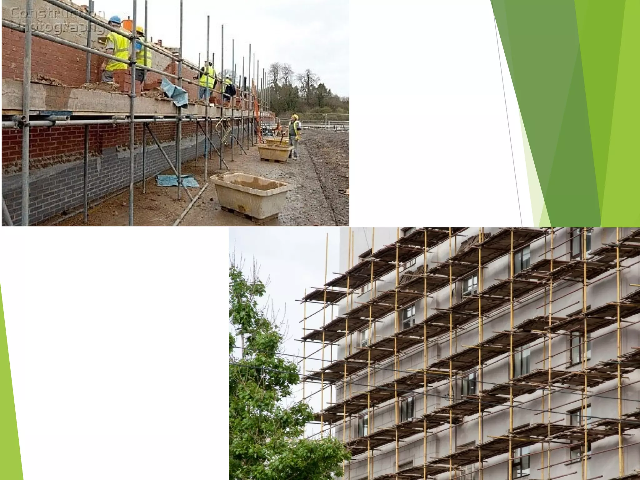
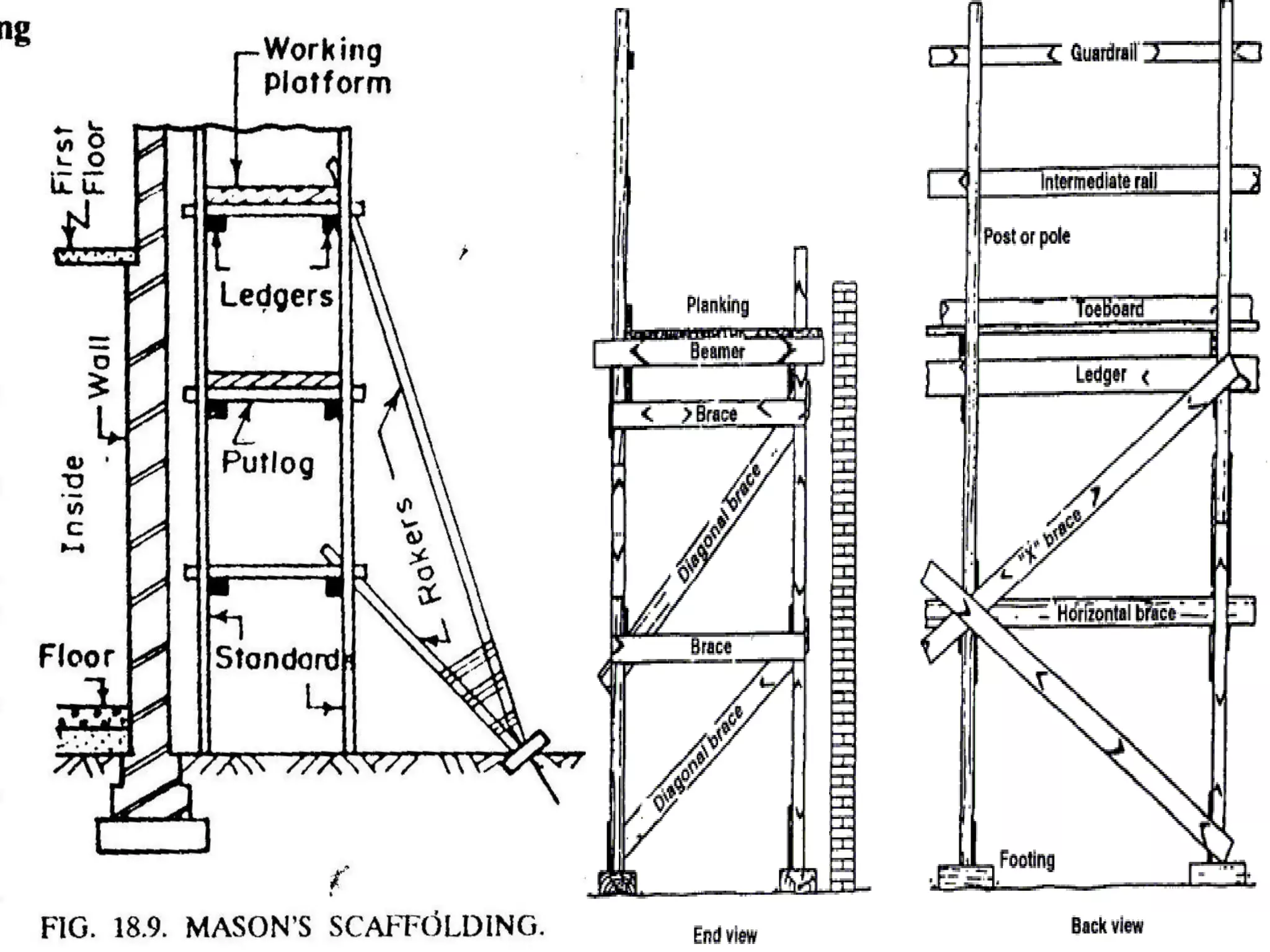
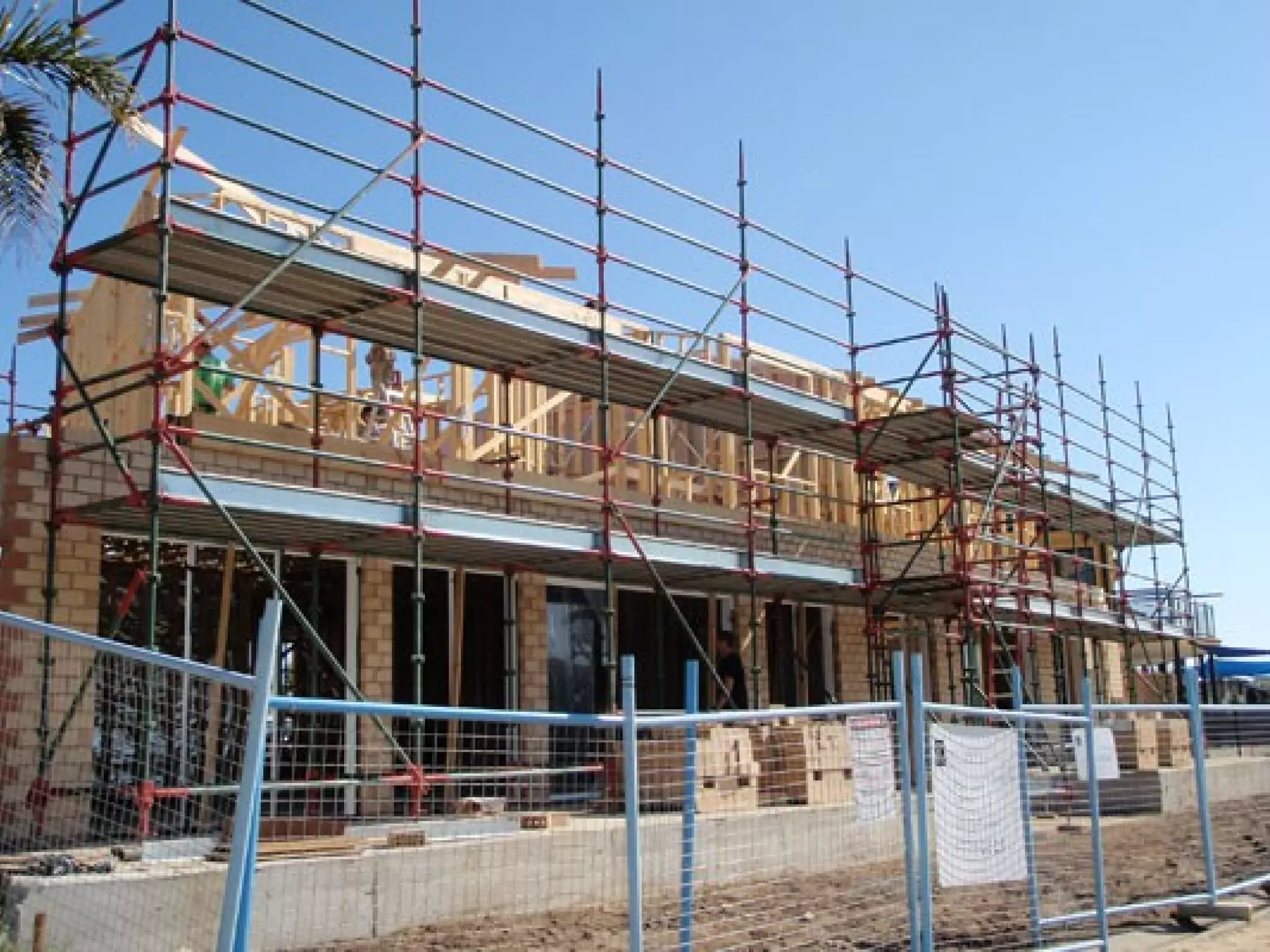
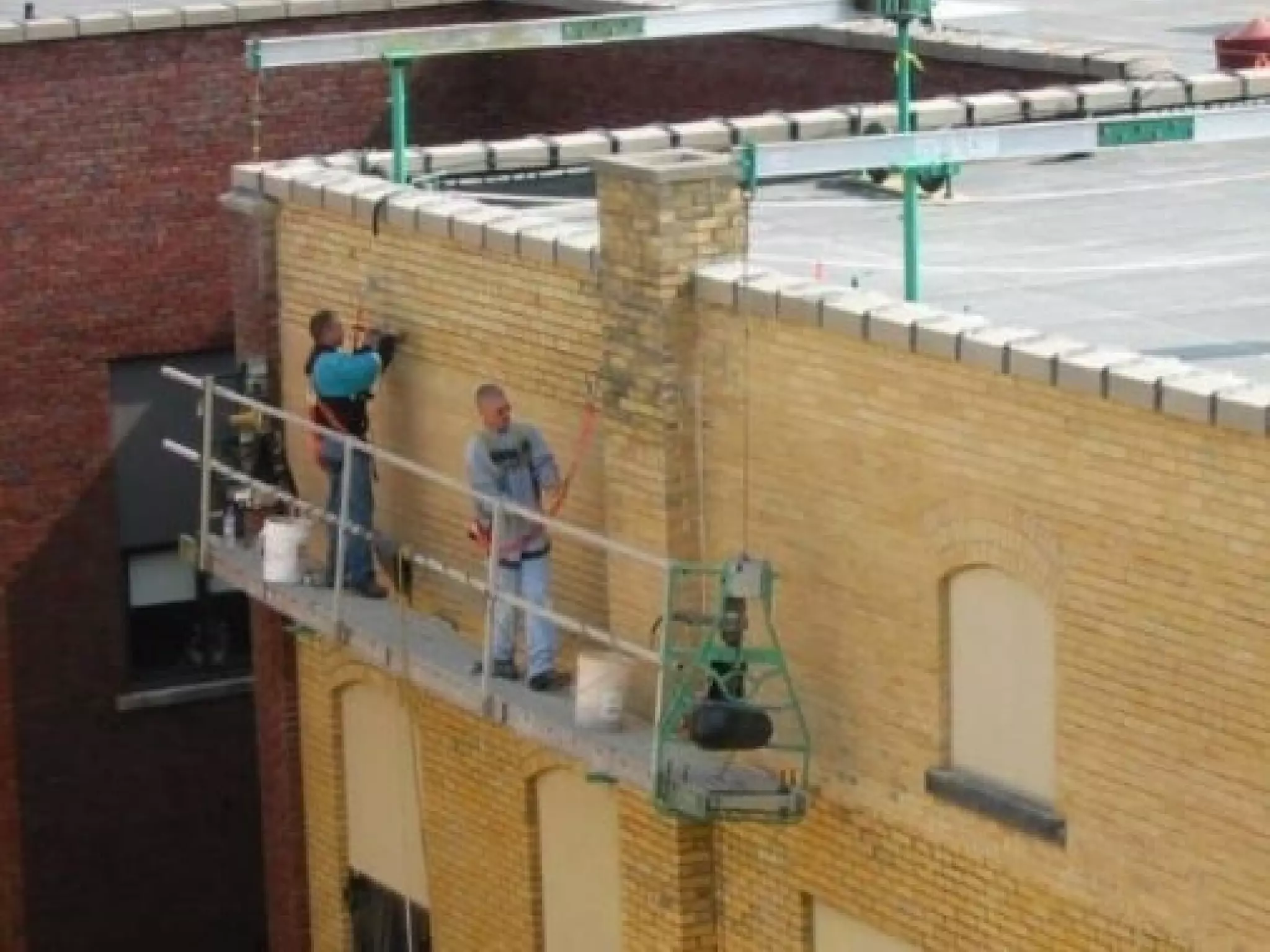
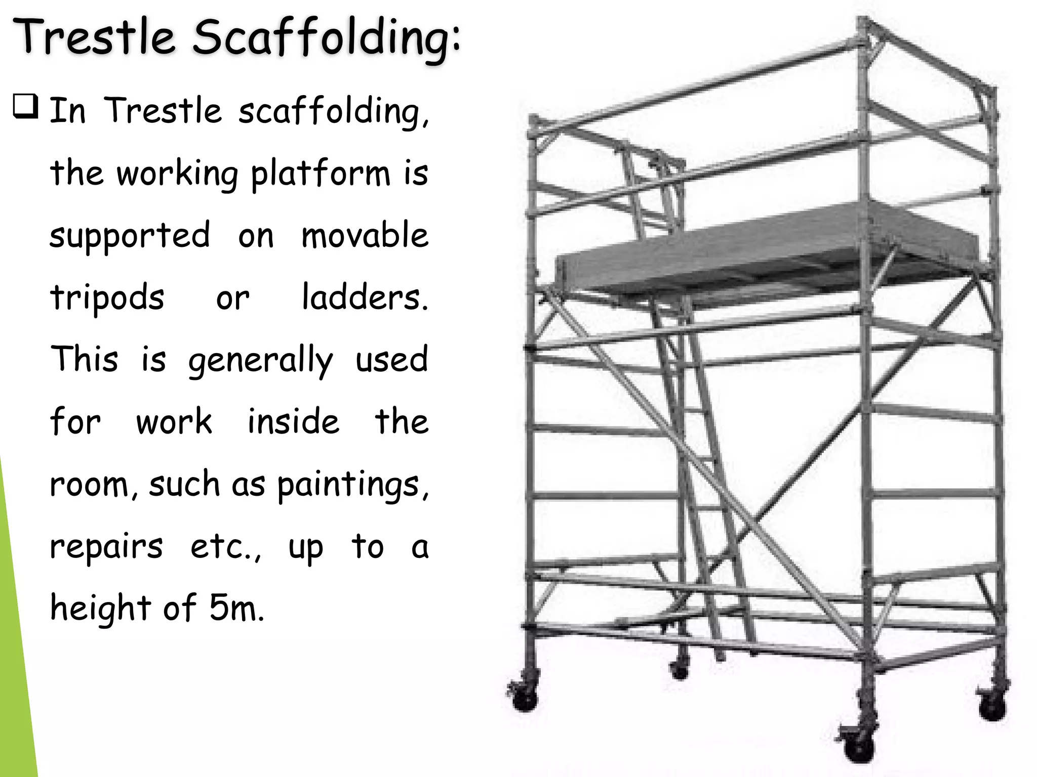
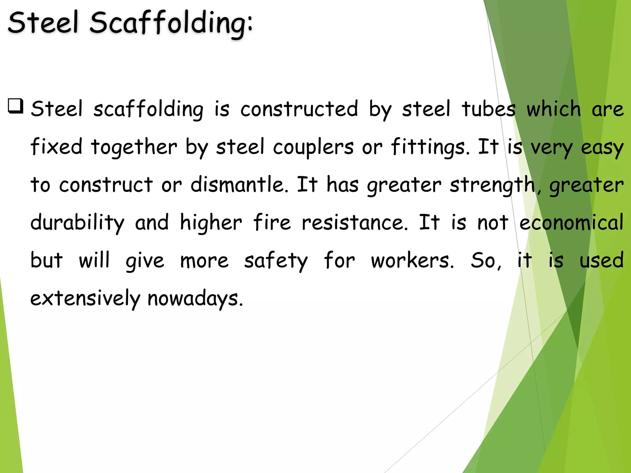
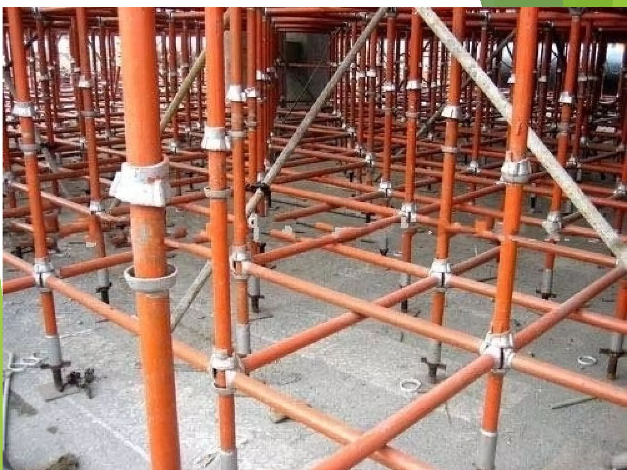
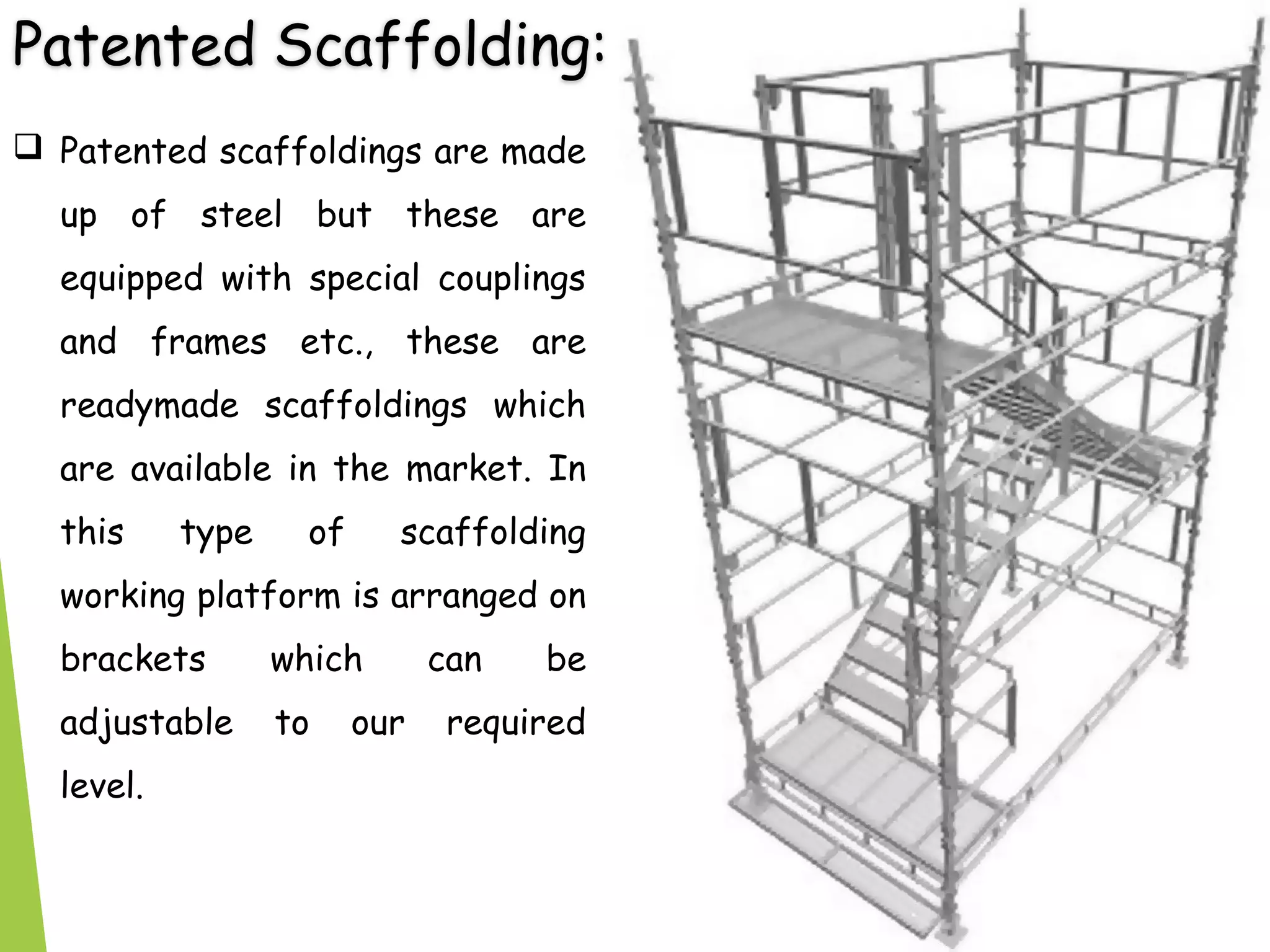


The document discusses temporary works in building construction, specifically focusing on methods of timbering trenches, shoring, underpinning, and scaffolding. It elaborates on various techniques such as stay bracing, box sheeting, and vertical sheeting for trench support, along with types of shoring like raking, flying, and dead shores. Additionally, it details underpinning methods for strengthening foundations and various scaffolding types used in construction to support work at heights.