Downloaded 335 times

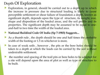
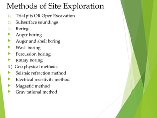
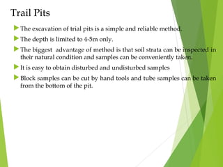
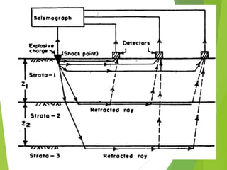
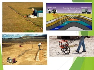
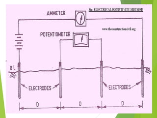

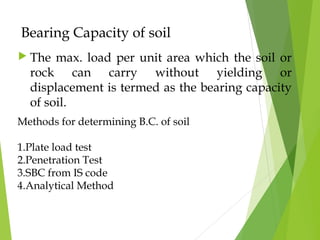
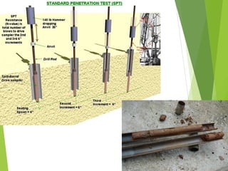
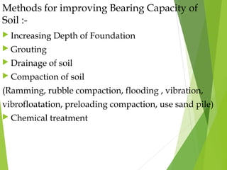

The document details the sub-surface investigation procedures necessary for building construction, focusing on the assessment of soil properties and geological features. It covers the purpose of site exploration, depth of investigation, various methods including trial pits, boring techniques, and geo-physical methods, along with the difference between disturbed and undisturbed soil samples. Finally, it addresses the importance of bearing capacity and methods for improving it, including grading soil and foundation depth adjustment.


![Geotechnical Engineering-II [Lec #23: Rankine Earth Pressure Theory]](https://cdn.slidesharecdn.com/ss_thumbnails/23-181123050516-thumbnail.jpg?width=640&height=640&fit=bounds)


![Foundation Eng'g-1, [Lecture Note] on Site Exploration [Chapter One].pptx](https://cdn.slidesharecdn.com/ss_thumbnails/foundationengg-1lecturenoteonsiteexplorationchapterone-251229124058-ecb78644-thumbnail.jpg?width=640&height=640&fit=bounds)


