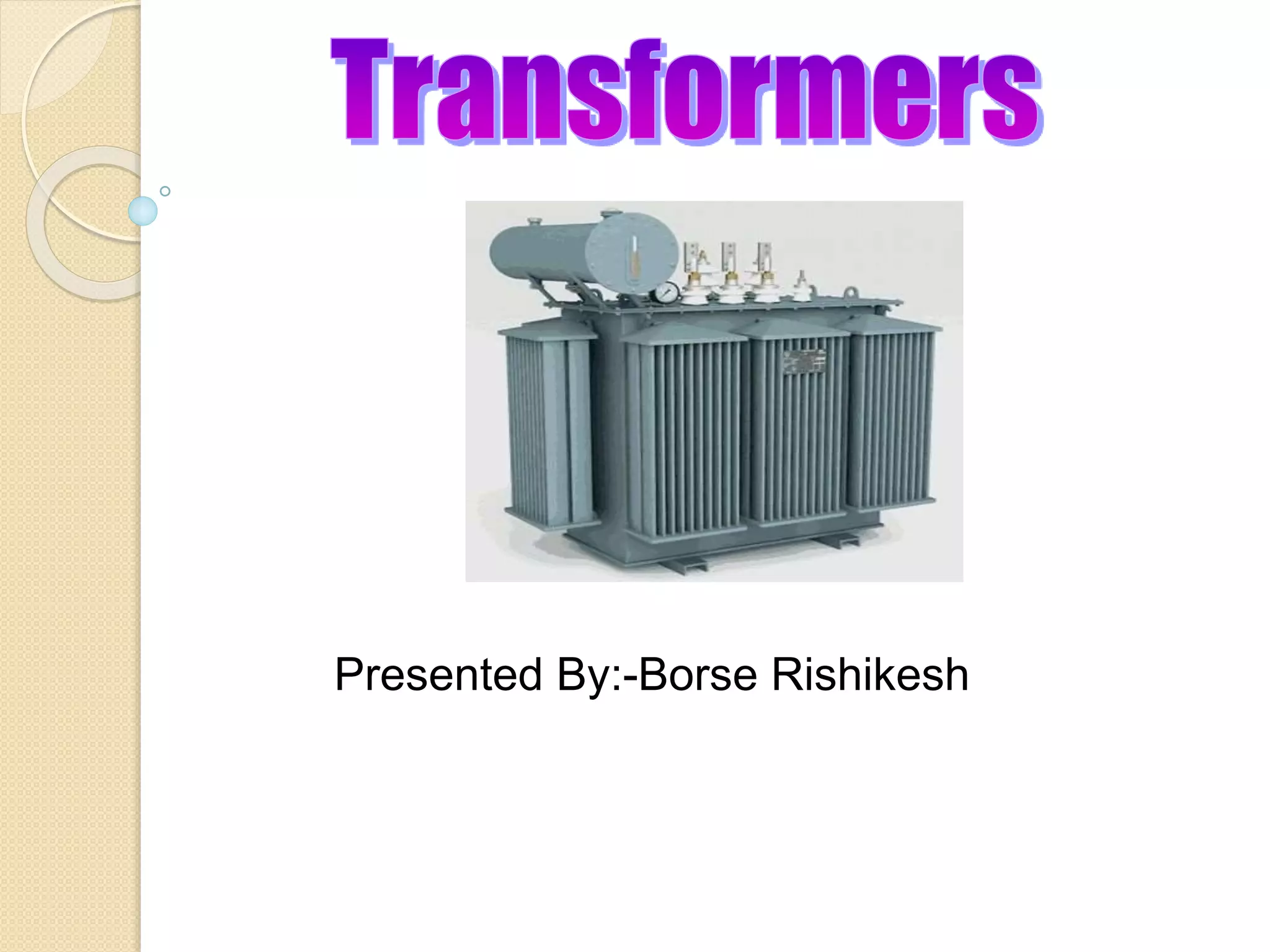
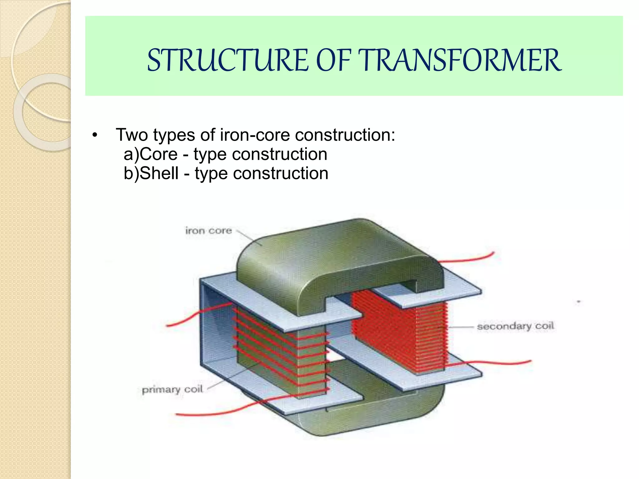
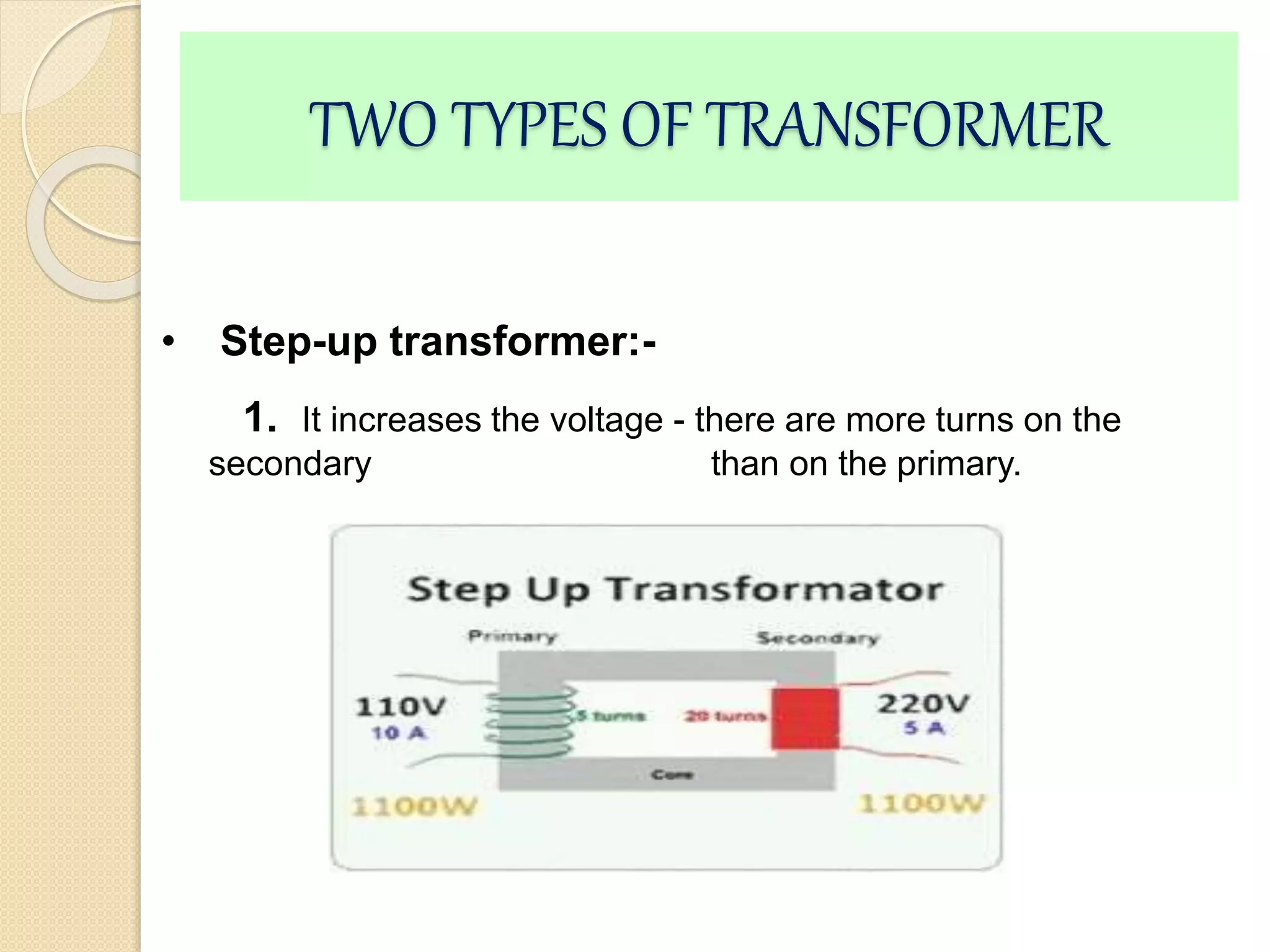
Presented By:-Borse Rishikesh
CONTENTS
•Introduction
•Structure Of Transformer
•Working
•Types
•Classification
•Applications
• Conclusion
INTRODUCTION
• It is a device that changes AC electrical power at one voltage level into
AC electrical power at another voltage level through the action of
magnetic field, without a change in frequency.
• It can be either to step-up or step down.
• There are two or more stationary electric circuits that are coupled
magnetically.
• Transformers provide much needed capability of changing the voltage
and current levels easily.It is a static machines.
• They are used to step-up generator voltage to an appropriate voltage
level for power transfer.
STRUCTURE OF TRANSFORMER
• Two types of iron-core construction:
a)Core - type construction
b)Shell - type construction
• SHELL - TYPE CONSTRUCTION:-
• CORE - TYPE CONSTRUCTION:-
HOW TRANSFORMER WORKS
Laminated soft iron
core
Primary coil Secondary coil
Input voltage
(a.c.)
Output voltage
(a.c.)
1.Primary coil – The incoming voltage Vp (voltage across primary coil)
is connected across this coil.
2.Secondary coil – This provides the output voltage Vs (voltage across
the secondary coil) to the external circuit.
3.Laminated iron core – This links the two coils magnetically.
 A transformer as a static device which helps in the transformation of
electric power one circuit to electric power of the same frequency in
another circuit.
 The voltage can be raised or lowered in a circuit,but with a proportional
increase or decrease in the current ratings.
 The main principle of operation of a transformer is mutual inductance
between two circuits which is linked by a common magnetic flux.
 A basic transformer consists of two coils that are electrically separate and
inductive, but are magnetically linked through a path of relcutance.
TWO TYPES OF TRANSFORMER
• Step-up transformer:-
1. It increases the voltage - there are more turns on the
secondary than on the primary.
• Step-down transformer-
1.It decreases the voltage - there are fewer turns on the secondary
than on the primary.
2. To step up the voltage by a factor of 10, there must be 10 times as
many turns on the secondary coil as on the primary. The turns ratio tells
us the factor by which the voltage will be changed.
• In terms of number of windings:-
1.Conventional transformer: two windings
2.Autotransformer: one winding
3.Others: more than two windings
• In terms of number of phases:-
1.Single-phase transformer
2.Three-phase transformer
• Depending on the voltage level at which the winding
is operated:-
1.Step-up transformer: primary winding is a low voltage (LV)
winding
2.Step-down transformer : primary winding is a high voltage (HV)
winding
Transformer Classification
• In power transmission and electronics.
• To minimise energy losses due to voltage drop in transmitting electricity
over long distance.
• They couple signals between electronic stages.
• They much loads with internal resistance so that there is maximum
power transfer.
• It can isolate two circuits electrically.
• It can increase or decrease the value of capacitor, an inductor or
resistance in AC circuit, Also the CT. & PT uesd power system and in
industry.
• It can be used to prevent DC from passing from one circuit to the
another.
APPLICATIONS
• AIR DRY VARNISHING:-
1.PREHEAT:-Heat all the transformer at 120 degree Celsius
for 2 h0urs in the oven to remove moisture in the transformer.
2.ACTUAL VARNISH:- Dip the Transformers in air-dry
varnish keep, then dipped for 30 min-1hr.Remove the transformers
and allow them to drip for 1 Hour.
3.TESTING:- After the completion of transformer, they takes
test on transformer with the help of testing machine for example:-
Current, Voltage and Frequency.
Soldering Iron/Solderbit:-
- Hand Soldering Process:-
1.Heating
2.Wetting the bit to improve heat transfer
3.Waiting until parts are sufficiently heated
4.Application of the solder wire: Fluxes parts to joined
5.Removing the wire
6.Removing the bit
CONCLUSION
 The method could possibly used for the transfer of
electricity across the country via the power lines. the circuit
was not supplying the most efficient or maximum efficiency,
due to the core losses not equaling the copper losses.
 So if you increases the voltage out, then the current out
must decreases. If you step up the voltage , so that voltage
output is double the voltage input.
Transformer

Transformer

  • 1.
  • 2.
  • 3.
    INTRODUCTION • It isa device that changes AC electrical power at one voltage level into AC electrical power at another voltage level through the action of magnetic field, without a change in frequency. • It can be either to step-up or step down. • There are two or more stationary electric circuits that are coupled magnetically. • Transformers provide much needed capability of changing the voltage and current levels easily.It is a static machines. • They are used to step-up generator voltage to an appropriate voltage level for power transfer.
  • 4.
    STRUCTURE OF TRANSFORMER •Two types of iron-core construction: a)Core - type construction b)Shell - type construction
  • 5.
    • SHELL -TYPE CONSTRUCTION:- • CORE - TYPE CONSTRUCTION:-
  • 6.
    HOW TRANSFORMER WORKS Laminatedsoft iron core Primary coil Secondary coil Input voltage (a.c.) Output voltage (a.c.)
  • 7.
    1.Primary coil –The incoming voltage Vp (voltage across primary coil) is connected across this coil. 2.Secondary coil – This provides the output voltage Vs (voltage across the secondary coil) to the external circuit. 3.Laminated iron core – This links the two coils magnetically.  A transformer as a static device which helps in the transformation of electric power one circuit to electric power of the same frequency in another circuit.  The voltage can be raised or lowered in a circuit,but with a proportional increase or decrease in the current ratings.  The main principle of operation of a transformer is mutual inductance between two circuits which is linked by a common magnetic flux.  A basic transformer consists of two coils that are electrically separate and inductive, but are magnetically linked through a path of relcutance.
  • 8.
    TWO TYPES OFTRANSFORMER • Step-up transformer:- 1. It increases the voltage - there are more turns on the secondary than on the primary.
  • 9.
    • Step-down transformer- 1.Itdecreases the voltage - there are fewer turns on the secondary than on the primary. 2. To step up the voltage by a factor of 10, there must be 10 times as many turns on the secondary coil as on the primary. The turns ratio tells us the factor by which the voltage will be changed.
  • 10.
    • In termsof number of windings:- 1.Conventional transformer: two windings 2.Autotransformer: one winding 3.Others: more than two windings • In terms of number of phases:- 1.Single-phase transformer 2.Three-phase transformer • Depending on the voltage level at which the winding is operated:- 1.Step-up transformer: primary winding is a low voltage (LV) winding 2.Step-down transformer : primary winding is a high voltage (HV) winding Transformer Classification
  • 11.
    • In powertransmission and electronics. • To minimise energy losses due to voltage drop in transmitting electricity over long distance. • They couple signals between electronic stages. • They much loads with internal resistance so that there is maximum power transfer. • It can isolate two circuits electrically. • It can increase or decrease the value of capacitor, an inductor or resistance in AC circuit, Also the CT. & PT uesd power system and in industry. • It can be used to prevent DC from passing from one circuit to the another. APPLICATIONS
  • 12.
    • AIR DRYVARNISHING:- 1.PREHEAT:-Heat all the transformer at 120 degree Celsius for 2 h0urs in the oven to remove moisture in the transformer. 2.ACTUAL VARNISH:- Dip the Transformers in air-dry varnish keep, then dipped for 30 min-1hr.Remove the transformers and allow them to drip for 1 Hour. 3.TESTING:- After the completion of transformer, they takes test on transformer with the help of testing machine for example:- Current, Voltage and Frequency.
  • 13.
    Soldering Iron/Solderbit:- - HandSoldering Process:- 1.Heating 2.Wetting the bit to improve heat transfer 3.Waiting until parts are sufficiently heated 4.Application of the solder wire: Fluxes parts to joined 5.Removing the wire 6.Removing the bit
  • 14.
    CONCLUSION  The methodcould possibly used for the transfer of electricity across the country via the power lines. the circuit was not supplying the most efficient or maximum efficiency, due to the core losses not equaling the copper losses.  So if you increases the voltage out, then the current out must decreases. If you step up the voltage , so that voltage output is double the voltage input.