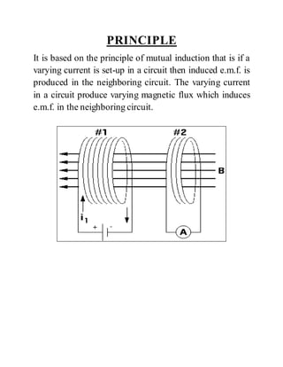
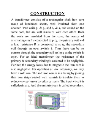
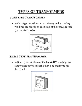
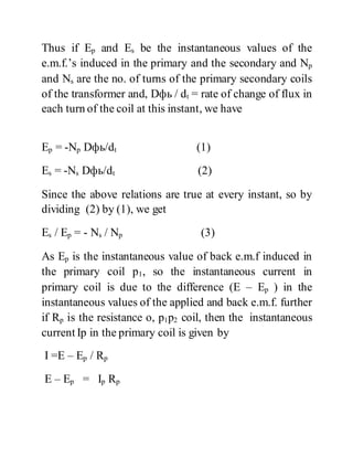
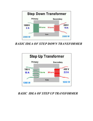
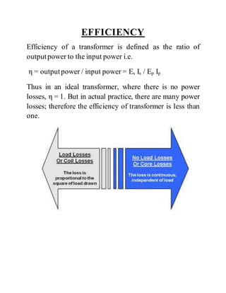
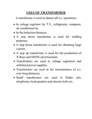
PHYSICS INVESTIGATORY
PROJECT
TOPIC: TRANSFORMER
INTRODUCTION
Transformer is a device used for converting a low
alternating voltage to a high alternating voltage or a high
alternating voltage into a low alternating voltage. It is a
static electrical device that transfers energy by inductive
coupling between its winding circuits. Transformers range
in size from a thumbnail-sized coupling transformer
hidden inside a stage microphone to huge units weighing
hundreds of tons used in power plant substations or to
interconnect portions of the power grid. All operate on the
same basic principles, although the range of designs is
wide. While new technologies have eliminated the need
for transformers in some electronic circuits, transformers
are still found in many electronic devices. Transformers
are essential for high-voltage electric power transmission,
which makes long-distance transmission economically
practical. A transformer is most widely used device in
both low and high current circuit. In a transformer, the
electrical energy transfer from one circuit to another
circuit takes place without the use of moving parts. A
transformer which increases the voltages is called a step-
up transformer. A transformer which decreases the A.C.
voltages is called a step-down transformer.
PRINCIPLE
It is based on the principle of mutual induction that is if a
varying current is set-up in a circuit then induced e.m.f. is
produced in the neighboring circuit. The varying current
in a circuit produce varying magnetic flux which induces
e.m.f. in the neighboring circuit.
CONSTRUCTION
A transformer consists of a rectangular shaft iron core
made of laminated sheets, well insulated from one
another. Two coils p1 & p2 and s1 & s2 are wound on the
same core, but are well insulated with each other. Both
the coils are insulated from the core, the source of
alternating e.m.f is connected to p1p2, the primary coil and
a load resistance R is connected to s1 s2, the secondary
coil through an open switch S. Thus there can be no
current through the secondary coil so long as the switch is
open. For an ideal transformer the resistance of the
primary & secondary winding is assumed to be negligible.
Further, the energy loses due to magnetic the iron core is
also negligible. For operation at low frequency, we may
have a soft iron. The soft iron core is insulating by joining
thin iron strips coated with varnish to insulate them to
reduce energy losses by eddy currents. The input circuit is
called primary. And the outputcircuit is called secondary.
TYPES OF TRANFORMERS
CORE TYPE TRANSFORMER
 In Core type transformer the primary and secondary
windings are placed on each side of the core.Thecore
type has two limbs.
SHELL TYPE TRANSFORMER
 In Shell type transformer the LV & HV windings are
sandwiched between each other. The shell type has
three limbs.
THEORY AND WORKING
When an altering e.m.f. is supplied to the primary coil
p1p2, an alternating current starts falling in it. The altering
current in the primary produces a changing magnetic flux,
which induces altering voltage in the primary as well as in
the secondary. In a good-transformer, whole of the
magnetic flux linked with primary is also linked with the
secondary, and then the induced e.m.f. induced in each
turn of the secondary is equal to that induced in each turn
of the primary.
Thus if Ep and Es be the instantaneous values of the
e.m.f.’s induced in the primary and the secondary and Np
and Ns are the no. of turns of the primary secondary coils
of the transformer and, Dфь / dt = rate of change of flux in
each turn of the coil at this instant, we have
Ep = -Np Dфь/dt (1)
Es = -Ns Dфь/dt (2)
Since the above relations are true at every instant, so by
dividing (2) by (1), we get
Es / Ep = - Ns / Np (3)
As Ep is the instantaneous value of back e.m.f induced in
the primary coil p1, so the instantaneous current in
primary coil is due to the difference (E – Ep ) in the
instantaneous values of the applied and back e.m.f. further
if Rp is the resistance o, p1p2 coil, then the instantaneous
current Ip in the primary coil is given by
I =E – Ep / Rp
E – Ep = Ip Rp
When the resistance of the primary is small, Rp Ip can be
neglected so therefore
E – Ep = 0 or Ep = E
Thus back e.m.f = input e.m.f
Hence equation 3 can be written as Es / Ep = Es / E =
outpute.m.f / input e.m.f = Ns / Np = K
Where K is a constant called turns or transformation ratio.
In a step up transformer
Es > E so K > 1, hence Ns > Np
In a step down transformer
Es < E so K < 1, hence Ns < Np
Ip=value of primary current at the same instant t
Is =value of sec. current at this instant,
Input power at the instant t = Ep Ip
Output power at the same instant = Es Is
If there are no losses of power in the transformer, then
Input power = outputpower or
Ep Ip = Es Is Or
Es / Ep = Ip / Is = K
In a step up transformer
As k > 1, so Ip > Is or Is < Ip
i.e. current in secondary is weaker when secondary
voltage is higher.
Hence, whatever we gain in voltage, we lose in current in
the same ratio.
Similarly it can be shown, that in a step down
transformer, whatever we lose in voltage, we gain in
current in the same ratio.Thus a step up transformer in
reality steps down the current & a step down transformer
steps up the current.
BASIC IDEA OF STEP DOWN TRANSFORMER
BASIC IDEA OF STEP UP TRANSFORMER
EFFICIENCY
Efficiency of a transformer is defined as the ratio of
outputpower to the input power i.e.
η = outputpower / input power = Es Is / Ep Ip
Thus in an ideal transformer, where there is no power
losses, η = 1. But in actual practice, there are many power
losses; therefore the efficiency of transformer is less than
one.
ENERGY LOSSES
In practice, the output energy of a transformer is always
less than the input energy, because energy losses occur
due to a number of reasons as explained below.
1. Loss of Magnetic Flux: The coupling between the coils
is seldom perfect. So, whole of the magnetic flux
produced by the primary coil is not linked up with the
secondary coil.
2. Iron Loss: In actual iron cores in spite of lamination,
eddy currents are produced. The magnitude of eddy
current may, however be small. And a part of energy is
lost as the heat produced in the iron core.
3. Copper Loss: In practice, the coils of the transformer
possess resistance. So a part of the energy is lost due to
the heat produced in the resistance of the coil.
4. Hysteresis Loss: The alternating current in the coil
tapes the iron core through complete cycle of
magnetization. So Energy is lost due to hysteresis.
5. Magneto restriction: The alternating current in the
transformer set its parts in to vibrations and sound is
produced. It is called humming. Thus, a part of energy is
lost due to humming.
USES OF TRANSFORMER
A transformer is used in almost all a.c. operations
 In voltage regulator for T.V., refrigerator, computer,
air conditioneretc.
 In the induction furnaces.
 A step down transformer is used for welding
purposes.
 A step down transformer is used for obtaining large
current.
 A step up transformer is used for the production of
X-Rays and NEON advertisement.
 Transformers are used in voltage regulators and
stabilized power supplies.
 Transformers are used in the transmissions of a.c.
over long distances.
 Small transformers are used in Radio sets,
telephones, loud speakers and electric bells etc.
Physics investigatory project

Physics investigatory project

  • 1.
  • 2.
    INTRODUCTION Transformer is adevice used for converting a low alternating voltage to a high alternating voltage or a high alternating voltage into a low alternating voltage. It is a static electrical device that transfers energy by inductive coupling between its winding circuits. Transformers range in size from a thumbnail-sized coupling transformer hidden inside a stage microphone to huge units weighing hundreds of tons used in power plant substations or to interconnect portions of the power grid. All operate on the same basic principles, although the range of designs is wide. While new technologies have eliminated the need for transformers in some electronic circuits, transformers are still found in many electronic devices. Transformers are essential for high-voltage electric power transmission, which makes long-distance transmission economically practical. A transformer is most widely used device in both low and high current circuit. In a transformer, the electrical energy transfer from one circuit to another circuit takes place without the use of moving parts. A transformer which increases the voltages is called a step- up transformer. A transformer which decreases the A.C. voltages is called a step-down transformer.
  • 3.
    PRINCIPLE It is basedon the principle of mutual induction that is if a varying current is set-up in a circuit then induced e.m.f. is produced in the neighboring circuit. The varying current in a circuit produce varying magnetic flux which induces e.m.f. in the neighboring circuit.
  • 4.
    CONSTRUCTION A transformer consistsof a rectangular shaft iron core made of laminated sheets, well insulated from one another. Two coils p1 & p2 and s1 & s2 are wound on the same core, but are well insulated with each other. Both the coils are insulated from the core, the source of alternating e.m.f is connected to p1p2, the primary coil and a load resistance R is connected to s1 s2, the secondary coil through an open switch S. Thus there can be no current through the secondary coil so long as the switch is open. For an ideal transformer the resistance of the primary & secondary winding is assumed to be negligible. Further, the energy loses due to magnetic the iron core is also negligible. For operation at low frequency, we may have a soft iron. The soft iron core is insulating by joining thin iron strips coated with varnish to insulate them to reduce energy losses by eddy currents. The input circuit is called primary. And the outputcircuit is called secondary.
  • 5.
    TYPES OF TRANFORMERS CORETYPE TRANSFORMER  In Core type transformer the primary and secondary windings are placed on each side of the core.Thecore type has two limbs. SHELL TYPE TRANSFORMER  In Shell type transformer the LV & HV windings are sandwiched between each other. The shell type has three limbs.
  • 6.
    THEORY AND WORKING Whenan altering e.m.f. is supplied to the primary coil p1p2, an alternating current starts falling in it. The altering current in the primary produces a changing magnetic flux, which induces altering voltage in the primary as well as in the secondary. In a good-transformer, whole of the magnetic flux linked with primary is also linked with the secondary, and then the induced e.m.f. induced in each turn of the secondary is equal to that induced in each turn of the primary.
  • 7.
    Thus if Epand Es be the instantaneous values of the e.m.f.’s induced in the primary and the secondary and Np and Ns are the no. of turns of the primary secondary coils of the transformer and, Dфь / dt = rate of change of flux in each turn of the coil at this instant, we have Ep = -Np Dфь/dt (1) Es = -Ns Dфь/dt (2) Since the above relations are true at every instant, so by dividing (2) by (1), we get Es / Ep = - Ns / Np (3) As Ep is the instantaneous value of back e.m.f induced in the primary coil p1, so the instantaneous current in primary coil is due to the difference (E – Ep ) in the instantaneous values of the applied and back e.m.f. further if Rp is the resistance o, p1p2 coil, then the instantaneous current Ip in the primary coil is given by I =E – Ep / Rp E – Ep = Ip Rp
  • 8.
    When the resistanceof the primary is small, Rp Ip can be neglected so therefore E – Ep = 0 or Ep = E Thus back e.m.f = input e.m.f Hence equation 3 can be written as Es / Ep = Es / E = outpute.m.f / input e.m.f = Ns / Np = K Where K is a constant called turns or transformation ratio. In a step up transformer Es > E so K > 1, hence Ns > Np In a step down transformer Es < E so K < 1, hence Ns < Np Ip=value of primary current at the same instant t Is =value of sec. current at this instant, Input power at the instant t = Ep Ip Output power at the same instant = Es Is
  • 9.
    If there areno losses of power in the transformer, then Input power = outputpower or Ep Ip = Es Is Or Es / Ep = Ip / Is = K In a step up transformer As k > 1, so Ip > Is or Is < Ip i.e. current in secondary is weaker when secondary voltage is higher. Hence, whatever we gain in voltage, we lose in current in the same ratio. Similarly it can be shown, that in a step down transformer, whatever we lose in voltage, we gain in current in the same ratio.Thus a step up transformer in reality steps down the current & a step down transformer steps up the current.
  • 10.
    BASIC IDEA OFSTEP DOWN TRANSFORMER BASIC IDEA OF STEP UP TRANSFORMER
  • 11.
    EFFICIENCY Efficiency of atransformer is defined as the ratio of outputpower to the input power i.e. η = outputpower / input power = Es Is / Ep Ip Thus in an ideal transformer, where there is no power losses, η = 1. But in actual practice, there are many power losses; therefore the efficiency of transformer is less than one.
  • 12.
    ENERGY LOSSES In practice,the output energy of a transformer is always less than the input energy, because energy losses occur due to a number of reasons as explained below. 1. Loss of Magnetic Flux: The coupling between the coils is seldom perfect. So, whole of the magnetic flux produced by the primary coil is not linked up with the secondary coil. 2. Iron Loss: In actual iron cores in spite of lamination, eddy currents are produced. The magnitude of eddy current may, however be small. And a part of energy is lost as the heat produced in the iron core. 3. Copper Loss: In practice, the coils of the transformer possess resistance. So a part of the energy is lost due to the heat produced in the resistance of the coil. 4. Hysteresis Loss: The alternating current in the coil tapes the iron core through complete cycle of magnetization. So Energy is lost due to hysteresis.
  • 13.
    5. Magneto restriction:The alternating current in the transformer set its parts in to vibrations and sound is produced. It is called humming. Thus, a part of energy is lost due to humming.
  • 14.
    USES OF TRANSFORMER Atransformer is used in almost all a.c. operations  In voltage regulator for T.V., refrigerator, computer, air conditioneretc.  In the induction furnaces.  A step down transformer is used for welding purposes.  A step down transformer is used for obtaining large current.  A step up transformer is used for the production of X-Rays and NEON advertisement.  Transformers are used in voltage regulators and stabilized power supplies.  Transformers are used in the transmissions of a.c. over long distances.  Small transformers are used in Radio sets, telephones, loud speakers and electric bells etc.