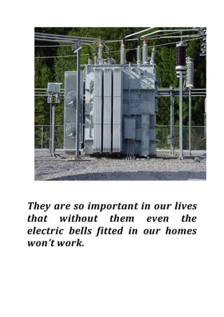
Kendriya vidyalaya
no. 2 belgaum cantt
PHYSICS INVESTIGATORY
PROJECT
ON
TRANSFORMERS
OMKAR MAJUKAR
XII-A
They are so important in our lives
that without them even the
electric bells fitted in our homes
won’t work.
CERTIFICATE
This is to certify that this dissertation is
a bonafide record of the project work
done by OMKAR MAJUKAR of class 12th
‘A’ (science) on “TRANSFORMERS” under the
guidance and supervision in partial
fulfilment of the requirements for
appearing in AISSCE March 2015.
PRINCIPAL TEACHER IN CHARGE
EXTERNAL EXAMINER
ACKNOWLEDGEMENT
I would like to express a deep sense of
thanks and gratitude to my project guide
Mr. Kashid sir for guiding me immensely
through the course of this project. He
always evinced keen interest in my work.
His constructive advice and constant
motivation have been responsible for the
completion of this project.
OMKAR MAJUKAR
XII-A
INTRODUCTION
The transformer is a device used for converting a
low alternating voltage to a high alternating
voltage or a high alternating voltage into a low
alternating voltage. It is a static electrical device
that transfers energy by inductive coupling
between its winding circuits. Transformers range
in size from a thumbnail-sized coupling
transformer hidden inside a stage microphone to
huge units weighing hundreds of tons used in
power plant substations or to interconnect
portions of the power grid. All operate on the
same basic principles, although the range of
designs is wide. While new technologies have
eliminated the need for transformers in some
electronic circuits, transformers are still found in
many electronic devices. Transformers are
essential for high-voltage electric power
transmission, which makes long-distance
transmission economically practical. A
transformer is most widely used device in both
low and high current circuit. In a transformer, the
electrical energy transfer from one circuit to
another circuit takes place without the use of
moving parts. A transformer which increases the
voltages is called a step-up transformer. A
transformer which decreases the A.C. voltages is
called a step-down transformer.
Transformer is, therefore, an essential
piece of apparatus both for high and low current
circuits.
Close-up of single-phase pole mount transformer.
PRINCIPLE
It is based on the principle of mutual
induction that is if a varying current is set-up
in a circuit then induced e.m.f. is produced in
the neighboring circuit. The varying current
in a circuit produce varying magnetic flux
which induces e.m.f. in the neighboring
circuit.
CONSTRUCTION
A transformer consists of a rectangular shaft
iron core made of laminated sheets, well
insulated from one another. Two coils p1 & p2
and s1 & s2 are wound on the same core, but
are well insulated with each other. Note that
the both the coils are insulated from the core,
the source of alternating e.m.f is connected to
p1p2, the primary coil and a load resistance R
is connected to s1 s2, the secondary coil
through an open switch S. thus there can be
no current through the sec. coil so long as the
switch is open. For an ideal transformer, we
assume that the resistance of the primary &
secondary winding is negligible. Further, the
energy loses due to magnetic the iron core is
also negligible. For operation at low
frequency, we may have a soft iron. The soft
iron core is insulating by joining thin iron
strips coated with varnish to insulate them to
reduce energy losses by eddy currents. The
input circuit is called primary. And the output
circuit is called secondary.
An ideal voltage step-down transformer. The secondary current
arises from the action of the secondary EMF on the (not shown) load
impedence.
The ideal transformer as a circuit element
THEORY AND WORKING
When an altering e.m.f. is supplied to the
primary coil p1p2, an alternating current
starts falling in it. The altering current in the
primary produces a changing magnetic flux,
which induces altering voltage in the primary
as well as in the secondary. In a good-
transformer, whole of the magnetic flux
linked with primary is also linked with the
secondary, and then the induced e.m.f.
induced in each turn of the secondary is equal
to that induced in each turn of the primary.
Thus if Ep and Es be the instantaneous values
of the e.m.f.’s induced in the primary and the
secondary and Np and Ns are the no. of turns
of the primary secondary coils of the
transformer and, Dфь / dt = rate of change of
flux in each turn of the coil at this instant, we
have
Ep = -Np Dфь/dt ----------------------------(1)
Es = -Ns Dфь/dt ---------------------(2)
Since the above relations are true at every
instant, so by dividing (2) by (1), we get
Es / Ep = - Ns / Np ---------------------(3)
As Ep is the instantaneous value of back e.m.f
induced in the primary coil p1, so the
instantaneous current in primary coil is due
to the difference (E – Ep ) in the instantaneous
values of the applied and back e.m.f. further if
Rp is the resistance o, p1p2 coil, then
the instantaneous current Ip in the primary
coil is given by
I =E – Ep / Rp
E – Ep = Ip Rp
When the resistance of the primary is small,
Rp Ip can be neglected so therefore
E – Ep = 0 or Ep = E
Thus back e.m.f = input e.m.f
Hence equation (3) can be written as
Es / Ep = Es / E = output e.m.f / input e.m.f = Ns / Np = K
Where K is constant, called turn or
transformation ratio.
In a step up transformer
Es > E so K > 1,
hence Ns > Np
In a step down transformer
Es < E so K < 1,
hence Ns < Np
If Ip=value of primary current at the same
instant t
And Is =value of sec. current at this instant,
then Input power at the instant t = Ep Ip and
Output power at the same instant = Es Is
If there are no losses of power in the
transformer, then
Input power = output power
or
Ep Ip = Es Is
or
Es / Ep = Ip / Is = K
In a step up transformer
As k > 1, so Ip > Is or Is < Ip
I.e. current in sec. is weaker when secondary
voltage is higher. Hence, whatever we gain in
voltage, we lose in current in the same ratio.
Similarly it can be shown, that in a step down
transformer, whatever we lose in voltage, we
gain in current in the same ratio. Thus a step
up transformer in reality steps down the
current & a step down transformer steps up
the current.
BASIC IDEA OF STEP DOWN TRANSFORMER
BASIC IDEA OF STEP UP TRANSFORMER
EFFICIENCY
Efficiency of a transformer is defined as the
ratio of output power to the input power i.e.
η = output power / input power = Es Is / Ep Ip
Thus in an ideal transformer, where there is
no power losses, η = 1. But in actual practice,
there are many power losses; therefore the
efficiency of transformer is less than one.
ENERGY LOSSES
In practice, the output energy of a
transformer is always less than the input
energy, because energy losses occur due to a
number of reasons as explained below.
1. Loss of Magnetic Flux: The coupling between the coils
is seldom perfect. So, whole of the magnetic flux produced by
the primary coil is not linked up with the secondary coil.
2. Iron Loss: In actual iron cores in spite of lamination,
Eddy currents are produced. The magnitude of eddy current
may, however be small. And a part of energy is lost as the
heat produced in the iron core.
3. Copper Loss: In practice, the coils of the transformer
possess resistance. So a part of the energy is lost due to the
heat produced in the resistance of the coil.
4. Hysteresis Loss: The alternating current in the coil
tapes the iron core through complete cycle of
magnetization.So Energy is lost due to hysteresis.
5. Magneto restriction: The alternating current in the
Transformer may be set its parts in to vibrations and sound
may be produced. It is called humming. Thus, a part of
energy may be lost due to humming.
USES OF TRANSFORMER
A transformer is used in almost all a.c.
operations
 In voltage regulator for T.V., refrigerator,
computer, air conditioner etc.
 In the induction furnaces.
 A step down transformer is used for
welding purposes.
 A step down transformer is used for
obtaining large current.
 A step up transformer is used for the
production of X-Rays and NEON
advertisement.
 Transformers are used in voltage
regulators and stabilized power supplies.
 Transformers are used in the
transmissions of a.c. over long distances.
 Small transformers are used in Radio
sets, telephones, loud speakers and
electric bells etc.
A Big Transformer
Bibliography
The data used in this project was taken from the
following sources:
 www.google.com
 www.wikipedia.com
 physics NCERT textbook

Transformers

  • 1.
    Kendriya vidyalaya no. 2belgaum cantt PHYSICS INVESTIGATORY PROJECT ON TRANSFORMERS OMKAR MAJUKAR XII-A
  • 2.
    They are soimportant in our lives that without them even the electric bells fitted in our homes won’t work.
  • 3.
    CERTIFICATE This is tocertify that this dissertation is a bonafide record of the project work done by OMKAR MAJUKAR of class 12th ‘A’ (science) on “TRANSFORMERS” under the guidance and supervision in partial fulfilment of the requirements for appearing in AISSCE March 2015. PRINCIPAL TEACHER IN CHARGE EXTERNAL EXAMINER
  • 4.
    ACKNOWLEDGEMENT I would liketo express a deep sense of thanks and gratitude to my project guide Mr. Kashid sir for guiding me immensely through the course of this project. He always evinced keen interest in my work. His constructive advice and constant motivation have been responsible for the completion of this project. OMKAR MAJUKAR XII-A
  • 5.
    INTRODUCTION The transformer isa device used for converting a low alternating voltage to a high alternating voltage or a high alternating voltage into a low alternating voltage. It is a static electrical device that transfers energy by inductive coupling between its winding circuits. Transformers range in size from a thumbnail-sized coupling transformer hidden inside a stage microphone to huge units weighing hundreds of tons used in power plant substations or to interconnect portions of the power grid. All operate on the same basic principles, although the range of designs is wide. While new technologies have eliminated the need for transformers in some electronic circuits, transformers are still found in many electronic devices. Transformers are essential for high-voltage electric power transmission, which makes long-distance transmission economically practical. A transformer is most widely used device in both low and high current circuit. In a transformer, the electrical energy transfer from one circuit to another circuit takes place without the use of moving parts. A transformer which increases the
  • 6.
    voltages is calleda step-up transformer. A transformer which decreases the A.C. voltages is called a step-down transformer. Transformer is, therefore, an essential piece of apparatus both for high and low current circuits. Close-up of single-phase pole mount transformer.
  • 7.
    PRINCIPLE It is basedon the principle of mutual induction that is if a varying current is set-up in a circuit then induced e.m.f. is produced in the neighboring circuit. The varying current in a circuit produce varying magnetic flux which induces e.m.f. in the neighboring circuit.
  • 8.
    CONSTRUCTION A transformer consistsof a rectangular shaft iron core made of laminated sheets, well insulated from one another. Two coils p1 & p2 and s1 & s2 are wound on the same core, but are well insulated with each other. Note that the both the coils are insulated from the core, the source of alternating e.m.f is connected to p1p2, the primary coil and a load resistance R is connected to s1 s2, the secondary coil through an open switch S. thus there can be no current through the sec. coil so long as the switch is open. For an ideal transformer, we assume that the resistance of the primary & secondary winding is negligible. Further, the energy loses due to magnetic the iron core is also negligible. For operation at low frequency, we may have a soft iron. The soft iron core is insulating by joining thin iron strips coated with varnish to insulate them to reduce energy losses by eddy currents. The
  • 9.
    input circuit iscalled primary. And the output circuit is called secondary. An ideal voltage step-down transformer. The secondary current arises from the action of the secondary EMF on the (not shown) load impedence. The ideal transformer as a circuit element
  • 10.
    THEORY AND WORKING Whenan altering e.m.f. is supplied to the primary coil p1p2, an alternating current starts falling in it. The altering current in the primary produces a changing magnetic flux, which induces altering voltage in the primary as well as in the secondary. In a good- transformer, whole of the magnetic flux linked with primary is also linked with the secondary, and then the induced e.m.f. induced in each turn of the secondary is equal to that induced in each turn of the primary. Thus if Ep and Es be the instantaneous values of the e.m.f.’s induced in the primary and the secondary and Np and Ns are the no. of turns of the primary secondary coils of the transformer and, Dфь / dt = rate of change of flux in each turn of the coil at this instant, we have Ep = -Np Dфь/dt ----------------------------(1)
  • 11.
    Es = -NsDфь/dt ---------------------(2) Since the above relations are true at every instant, so by dividing (2) by (1), we get Es / Ep = - Ns / Np ---------------------(3) As Ep is the instantaneous value of back e.m.f induced in the primary coil p1, so the instantaneous current in primary coil is due to the difference (E – Ep ) in the instantaneous values of the applied and back e.m.f. further if Rp is the resistance o, p1p2 coil, then the instantaneous current Ip in the primary coil is given by I =E – Ep / Rp E – Ep = Ip Rp When the resistance of the primary is small, Rp Ip can be neglected so therefore E – Ep = 0 or Ep = E
  • 12.
    Thus back e.m.f= input e.m.f Hence equation (3) can be written as Es / Ep = Es / E = output e.m.f / input e.m.f = Ns / Np = K Where K is constant, called turn or transformation ratio. In a step up transformer Es > E so K > 1, hence Ns > Np In a step down transformer Es < E so K < 1, hence Ns < Np If Ip=value of primary current at the same instant t
  • 13.
    And Is =valueof sec. current at this instant, then Input power at the instant t = Ep Ip and Output power at the same instant = Es Is If there are no losses of power in the transformer, then Input power = output power or Ep Ip = Es Is or Es / Ep = Ip / Is = K In a step up transformer As k > 1, so Ip > Is or Is < Ip I.e. current in sec. is weaker when secondary voltage is higher. Hence, whatever we gain in voltage, we lose in current in the same ratio. Similarly it can be shown, that in a step down transformer, whatever we lose in voltage, we gain in current in the same ratio. Thus a step up transformer in reality steps down the current & a step down transformer steps up the current.
  • 14.
    BASIC IDEA OFSTEP DOWN TRANSFORMER BASIC IDEA OF STEP UP TRANSFORMER
  • 15.
    EFFICIENCY Efficiency of atransformer is defined as the ratio of output power to the input power i.e. η = output power / input power = Es Is / Ep Ip Thus in an ideal transformer, where there is no power losses, η = 1. But in actual practice, there are many power losses; therefore the efficiency of transformer is less than one.
  • 16.
    ENERGY LOSSES In practice,the output energy of a transformer is always less than the input energy, because energy losses occur due to a number of reasons as explained below. 1. Loss of Magnetic Flux: The coupling between the coils is seldom perfect. So, whole of the magnetic flux produced by the primary coil is not linked up with the secondary coil. 2. Iron Loss: In actual iron cores in spite of lamination, Eddy currents are produced. The magnitude of eddy current may, however be small. And a part of energy is lost as the heat produced in the iron core. 3. Copper Loss: In practice, the coils of the transformer possess resistance. So a part of the energy is lost due to the heat produced in the resistance of the coil. 4. Hysteresis Loss: The alternating current in the coil tapes the iron core through complete cycle of magnetization.So Energy is lost due to hysteresis. 5. Magneto restriction: The alternating current in the Transformer may be set its parts in to vibrations and sound may be produced. It is called humming. Thus, a part of energy may be lost due to humming.
  • 17.
    USES OF TRANSFORMER Atransformer is used in almost all a.c. operations  In voltage regulator for T.V., refrigerator, computer, air conditioner etc.  In the induction furnaces.  A step down transformer is used for welding purposes.  A step down transformer is used for obtaining large current.  A step up transformer is used for the production of X-Rays and NEON advertisement.  Transformers are used in voltage regulators and stabilized power supplies.  Transformers are used in the transmissions of a.c. over long distances.  Small transformers are used in Radio sets, telephones, loud speakers and electric bells etc.
  • 18.
  • 19.
    Bibliography The data usedin this project was taken from the following sources:  www.google.com  www.wikipedia.com  physics NCERT textbook