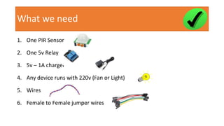
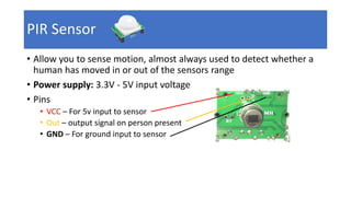
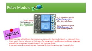
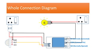
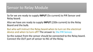
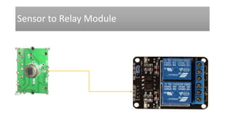
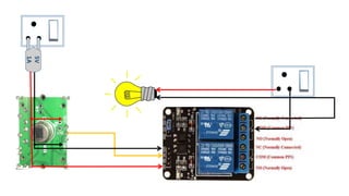
Operating Electrical Devices
with Motion Sensor
No controller, No coding
Santosh Kumar Kar
skkar.2k2@gmail.com
What we need
1. One PIR Sensor
2. One 5v Relay
3. 5v – 1A charger
4. Any device runs with 220v (Fan or Light)
5. Wires
6. Female to Female jumper wires
What we DON’T need
1. No need of any controller (raspberry pi, Arduino)
2. No need any coding
PIR Sensor
• Allow you to sense motion, almost always used to detect whether a
human has moved in or out of the sensors range
• Power supply: 3.3V - 5V input voltage
• Pins
• VCC – For 5v input to sensor
• Out – output signal on person present
• GND – For ground input to sensor
PIR Sensor
Relay Module
• Relay module is already integrated with Driver circuit on board (such
as transistor, Diode and resistor)
• Required to operate light, fan or other electrical devices in
accordance to an output signal from a sensor or controller.
• Here we take input from the PIR sensor to turn the light on when
someone present.
Relay Module
• There are relays with different channels such as 1 channel, 2 channel, 3 channel, …. n channel relays.
• I have used 2 channel relay and so the images. For your project I would recommend to use only single
channel relay because we are operating only one electrical device.
• If you want to use 2 sensors to operate 2 electrical devices then you can use 2 channel relay.
Whole Connection Diagram
GND
IN1
VOC
5V
1A
`
GND
OUT
VCC
NC (Normally Connected)
COM (Common Pin)
NO (Normally Opened)
• 5 volt with 1 amp charger
• 5 volt charging is required to 1) PIR Sensor and 2) Relay Board
• Charger has 2 points (red and black)
• Black cable will be connected to
• GND (Ground) pin of PIR Sensor
• GND (Ground) pin of Relay Board
• Red cable will be connected to
• VCC pin of PIR Sensor
• VOC pin of Relay Board
5v – 1A Charger input
5V
1A
• AC voltage which is connected to plug directly.
• It has 2 points – (+) Positive and (-) Negative
• One connection from the plug will be connected to the Relay board (COM
pin). You can use either positive or negative current to the relay, but let’s use
the (-) Negative current point.
• The other connection from the plug will be connected directly to the
electrical device such as Fan or Light. Let’s use the (+) Positive current point.
Note: The connection from the plug will be connected to relay COM (common pin)
port. And the NC (Normally Closed) port will be connected to the bulb. So there will
be switch in the relay which will operate this connection to the bulb after getting
ON/OFF signal from the sensor). If there is anyone near the sensor, so it will pass
signal from plug to the bulb through the relay switch (ON)
AC voltage (~230 volt) input
Sensor to Relay Module
So far we are ready to supply INPUT (5v current) to PIR Sensor and
Relay board.
Also we have are ready to supply INPUT (230v current) to the Relay
Board and the bulb.
But who will instruct the Relay board when to turn on the electrical
device and when to turn off? The answer is: the PIR Sensor.
So the output from the sensor should be connected to the Relay board.
Connect the OUT port of sensor to IN1 of the Relay.
Sensor to Relay Module
Relay to Electrical Device (Bulb)
This is the final connection in our project.
So far only one INPUT is connected to the bulb from the 230v plug pin.
Now the other INPUT to the bulb should be supplied from the relay.
This connection is the one which operates the bulb after getting input
from the PIR Sensor. If there is anyone present, the PIR sensor will send
the HIGH(1) signal to the relay and so the bulb will be turned ON. If no
one present, the PIR sensor will send LOW(0) signal to the relay and the
bulb will be turned OFF.
Get the connection from NC pin (Normally Connected) from relay
board and supply it to the bulb.
Relay to Electrical Device (Bulb)
5V
1A
Working
• Set the proper delay in the PIR sensor.
• Switch on the power plug for 5v and 230v input.
• It should turn on the light initially. Wait for a minute.
• Now if anyone is exposed to the sensor, the bulb should turn ON.
• Hid the sensor with a cloth, after some time delay it should turn OFF
Write to
skkar.2k2@gmail.com
Operating electrical devices with PIR sensor. No coding, No controller

Operating electrical devices with PIR sensor. No coding, No controller

  • 1.
    Operating Electrical Devices withMotion Sensor No controller, No coding Santosh Kumar Kar skkar.2k2@gmail.com
  • 2.
    What we need 1.One PIR Sensor 2. One 5v Relay 3. 5v – 1A charger 4. Any device runs with 220v (Fan or Light) 5. Wires 6. Female to Female jumper wires
  • 3.
    What we DON’Tneed 1. No need of any controller (raspberry pi, Arduino) 2. No need any coding
  • 4.
    PIR Sensor • Allowyou to sense motion, almost always used to detect whether a human has moved in or out of the sensors range • Power supply: 3.3V - 5V input voltage • Pins • VCC – For 5v input to sensor • Out – output signal on person present • GND – For ground input to sensor
  • 5.
  • 6.
    Relay Module • Relaymodule is already integrated with Driver circuit on board (such as transistor, Diode and resistor) • Required to operate light, fan or other electrical devices in accordance to an output signal from a sensor or controller. • Here we take input from the PIR sensor to turn the light on when someone present.
  • 7.
    Relay Module • Thereare relays with different channels such as 1 channel, 2 channel, 3 channel, …. n channel relays. • I have used 2 channel relay and so the images. For your project I would recommend to use only single channel relay because we are operating only one electrical device. • If you want to use 2 sensors to operate 2 electrical devices then you can use 2 channel relay.
  • 8.
    Whole Connection Diagram GND IN1 VOC 5V 1A ` GND OUT VCC NC(Normally Connected) COM (Common Pin) NO (Normally Opened)
  • 9.
    • 5 voltwith 1 amp charger • 5 volt charging is required to 1) PIR Sensor and 2) Relay Board • Charger has 2 points (red and black) • Black cable will be connected to • GND (Ground) pin of PIR Sensor • GND (Ground) pin of Relay Board • Red cable will be connected to • VCC pin of PIR Sensor • VOC pin of Relay Board 5v – 1A Charger input
  • 10.
    5v – 1ACharger input 5V 1A
  • 11.
    • AC voltagewhich is connected to plug directly. • It has 2 points – (+) Positive and (-) Negative • One connection from the plug will be connected to the Relay board (COM pin). You can use either positive or negative current to the relay, but let’s use the (-) Negative current point. • The other connection from the plug will be connected directly to the electrical device such as Fan or Light. Let’s use the (+) Positive current point. Note: The connection from the plug will be connected to relay COM (common pin) port. And the NC (Normally Closed) port will be connected to the bulb. So there will be switch in the relay which will operate this connection to the bulb after getting ON/OFF signal from the sensor). If there is anyone near the sensor, so it will pass signal from plug to the bulb through the relay switch (ON) AC voltage (~230 volt) input
  • 12.
    AC voltage (~230volt) input
  • 13.
    Sensor to RelayModule So far we are ready to supply INPUT (5v current) to PIR Sensor and Relay board. Also we have are ready to supply INPUT (230v current) to the Relay Board and the bulb. But who will instruct the Relay board when to turn on the electrical device and when to turn off? The answer is: the PIR Sensor. So the output from the sensor should be connected to the Relay board. Connect the OUT port of sensor to IN1 of the Relay.
  • 14.
  • 15.
    Relay to ElectricalDevice (Bulb) This is the final connection in our project. So far only one INPUT is connected to the bulb from the 230v plug pin. Now the other INPUT to the bulb should be supplied from the relay. This connection is the one which operates the bulb after getting input from the PIR Sensor. If there is anyone present, the PIR sensor will send the HIGH(1) signal to the relay and so the bulb will be turned ON. If no one present, the PIR sensor will send LOW(0) signal to the relay and the bulb will be turned OFF. Get the connection from NC pin (Normally Connected) from relay board and supply it to the bulb.
  • 16.
    Relay to ElectricalDevice (Bulb)
  • 17.
  • 18.
    Working • Set theproper delay in the PIR sensor. • Switch on the power plug for 5v and 230v input. • It should turn on the light initially. Wait for a minute. • Now if anyone is exposed to the sensor, the bulb should turn ON. • Hid the sensor with a cloth, after some time delay it should turn OFF
  • 19.