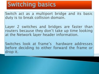
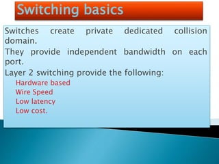
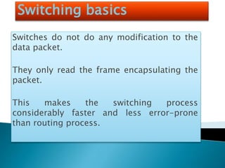
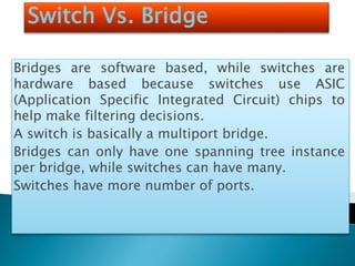
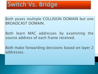
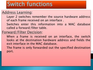
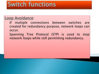
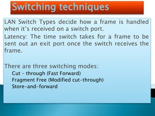
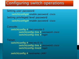
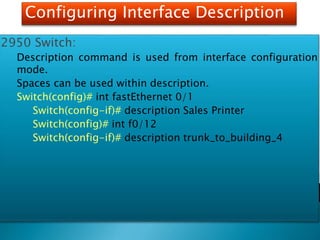
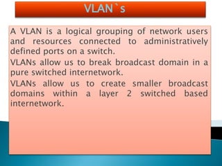
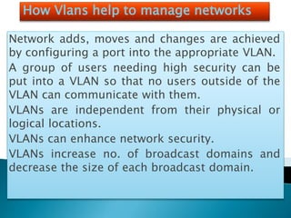
Switching
STP :Spanning
tree protocol
VLAN: Virtual
lan
VTP: Virtual
trunking
Protocol
INTER-VLAN
Switching basics
Switch act as a multiport bridge and its basic
duty is to break collision domain.
Layer 2 switches and bridges are faster than
routers because they don’t take up time looking
at the Network layer header information.
Switches look at frame’s hardware addresses
before deciding to either forward the frame or
drop it.
Switching basics
Switches create private dedicated collision
domain.
They provide independent bandwidth on each
port.
Layer 2 switching provide the following:
Hardware based
Wire Speed
Low latency
Low cost.
Switching basics
Switches do not do any modification to the
data packet.
They only read the frame encapsulating the
packet.
This makes the switching process
considerably faster and less error-prone
than routing process.
Switch Vs. Bridge
Bridges are software based, while switches are
hardware based because switches use ASIC
(Application Specific Integrated Circuit) chips to
help make filtering decisions.
A switch is basically a multiport bridge.
Bridges can only have one spanning tree instance
per bridge, while switches can have many.
Switches have more number of ports.
Switch Vs. Bridge
Both poses multiple COLLISION DOMAIN but one
BROADCAST DOMAIN.
Both learn MAC addresses by examining the
source address of each frame received.
Both make forwarding decisions based on layer 2
addresses.
Switch functions
Address Learning:
Layer 2 switches remember the source hardware address
of each frame received on an interface .
Switches enter this information into a MAC database
called a forward/filter table.
Forward/Filter Decision:
When a frame is received on an interface, the switch
looks at the destination hardware address and fields the
exit interface in the MAC database.
The frame is only forwarded out the specified destination
port.
Switch functions
Loop Avoidance:
If multiple connections between switches are
created for redundancy purpose, network loops can
occur.
Spanning Tree Protocol (STP) is used to stop
network loops while still permitting redundancy.
Switch Address learning
When switch is first powered on, the MAC forward/filter table is
empty.
When an interface receives a frame, the switch places the frame’s
source address in MAC forward/filter table, allowing it to
remember which interface the sending device is located on.
Switch then floods the network with this frame out of every port
except the source port because it has no idea where the
destination device actually located. If a device answers this
flooded frame and sends a frame back, then:
Switch takes the source address from that frame and place
the mac address in the database as well.
Switch associates this address with the interface that received
the frame.
Switching table
Switch addressed table
STP Spanning tree protocol
Its main task is to stop routing loops from occurring on
layer 2. (Bridges or Switches)
It monitors the network to find all links making sure
that no loops occur by shutting down the redundant
link.
It uses Spanning Tree Algorithm (STA), to first create a
topology database, then search out and destroy
redundant links.
With STP running, frames are only forwarded on the
STP, picked links.
Switching techniques
LAN Switch Types decide how a frame is handled
when it’s received on a switch port.
Latency: The time switch takes for a frame to be
sent out an exit port once the switch receives the
frame.
There are three switching modes:
Cut – through (Fast Forward)
Fragment Free (Modified cut-through)
Store-and-forward
Switching techniques
Cut-through (Fast Forward):
In this mode, the switch only waits for the destination
hardware address to be received before it looks up the
destination address in the MAC filter table.
Fragment Free (Modified cut-through):
In this mode, the switch checks the first 64 bytes of a frame
before forwarding it for fragmentation.
This is the default mode for catalyst 1900 series switch.
Store-and-forward:
In this mode, the complete frame is received on the switch’s
buffer, a CRC is run and then the switch looks up the
destination address in the MAC forward/filter table.
Different switching modes
within a frame
Configuring switch operations
We will cover following list of tasks:
Setting the password
Setting the hostname
Configuring the ip address and subnet masks
Setting a description on the interface
Erasing the switch configuration
Configuring VLANs
Adding VLAN membership to switch port.
Creating VTP domain.
Configuring trunking.
Configuring switch operations
Setting user password:
switch(config)# enable password cisco
Setting privileged level password
switch(config)# enable password cisco
Console:
switch(config)# line console 0
switch(config-line)# password cisco
switch(config-line)# login
Telnet:
switch(config)# line vty 0 15
switch(config-line)# password cisco
switch(config-line)# login
switch(config)# hostname LAN1
Configuring Interface Description
2950 Switch:
Description command is used from interface configuration
mode.
Spaces can be used within description.
Switch(config)# int fastEthernet 0/1
Switch(config-if)# description Sales Printer
Switch(config)# int f0/12
Switch(config-if)# description trunk_to_building_4
VLAN`s
A VLAN is a logical grouping of network users
and resources connected to administratively
defined ports on a switch.
VLANs allow us to break broadcast domain in a
pure switched internetwork.
VLANs allow us to create smaller broadcast
domains within a layer 2 switched based
internetwork.
How Vlans help to manage networks
Network adds, moves and changes are achieved
by configuring a port into the appropriate VLAN.
A group of users needing high security can be
put into a VLAN so that no users outside of the
VLAN can communicate with them.
VLANs are independent from their physical or
logical locations.
VLANs can enhance network security.
VLANs increase no. of broadcast domains and
decrease the size of each broadcast domain.
Broadcast control
All devices in a VLAN are member of same
broadcast domain and receive all broadcasts.
The broadcasts, by default, are filtered from all
ports on a switch that are not member of the same
VLAN.
This is one of the prime benefit that we get with a
VLAN based switched network, otherwise we would
have faced serious problem if all our users were in
same broadcast domain.
Vlan security
In a flat network anyone connecting to the physical
network could access the network resources located that
physical LAN.
In order to observe any/all traffic happening in that
network one has to simply plug a network analyzer into
the hub.
Users can join any workgroup by just plugging their
workstations into the existing hub.
By building VLANs and creating multiple broadcast
groups, administrators can now have control over each
port and user.
Since VLANs can be created in accordance with the
network resources a user requires, a switch can be
configured to inform a network management station of
any unauthorized access to network resources.
During inter VLAN communication, we can implement
restrictions on a router to achieve it.
Flexibility and Scalability
By assigning switch ports or users to VLAN groups
on a switch or group of switches, we gain
flexibility to add only the users we want into that
broadcast domain regardless of their physical
location.
When a VLAN becomes to big, we can create more
VLANs to keep broadcasts from consuming too
much bandwidth.
Switching basics
Switching basics
Switching basics
Switching basics

Switching

  • 1.
    Switching STP :Spanning tree protocol VLAN:Virtual lan VTP: Virtual trunking Protocol INTER-VLAN
  • 2.
    Switching basics Switch actas a multiport bridge and its basic duty is to break collision domain. Layer 2 switches and bridges are faster than routers because they don’t take up time looking at the Network layer header information. Switches look at frame’s hardware addresses before deciding to either forward the frame or drop it.
  • 3.
    Switching basics Switches createprivate dedicated collision domain. They provide independent bandwidth on each port. Layer 2 switching provide the following: Hardware based Wire Speed Low latency Low cost.
  • 4.
    Switching basics Switches donot do any modification to the data packet. They only read the frame encapsulating the packet. This makes the switching process considerably faster and less error-prone than routing process.
  • 5.
    Switch Vs. Bridge Bridgesare software based, while switches are hardware based because switches use ASIC (Application Specific Integrated Circuit) chips to help make filtering decisions. A switch is basically a multiport bridge. Bridges can only have one spanning tree instance per bridge, while switches can have many. Switches have more number of ports.
  • 6.
    Switch Vs. Bridge Bothposes multiple COLLISION DOMAIN but one BROADCAST DOMAIN. Both learn MAC addresses by examining the source address of each frame received. Both make forwarding decisions based on layer 2 addresses.
  • 7.
    Switch functions Address Learning: Layer2 switches remember the source hardware address of each frame received on an interface . Switches enter this information into a MAC database called a forward/filter table. Forward/Filter Decision: When a frame is received on an interface, the switch looks at the destination hardware address and fields the exit interface in the MAC database. The frame is only forwarded out the specified destination port.
  • 8.
    Switch functions Loop Avoidance: Ifmultiple connections between switches are created for redundancy purpose, network loops can occur. Spanning Tree Protocol (STP) is used to stop network loops while still permitting redundancy.
  • 9.
    Switch Address learning Whenswitch is first powered on, the MAC forward/filter table is empty. When an interface receives a frame, the switch places the frame’s source address in MAC forward/filter table, allowing it to remember which interface the sending device is located on. Switch then floods the network with this frame out of every port except the source port because it has no idea where the destination device actually located. If a device answers this flooded frame and sends a frame back, then: Switch takes the source address from that frame and place the mac address in the database as well. Switch associates this address with the interface that received the frame.
  • 10.
  • 11.
  • 12.
    STP Spanning treeprotocol Its main task is to stop routing loops from occurring on layer 2. (Bridges or Switches) It monitors the network to find all links making sure that no loops occur by shutting down the redundant link. It uses Spanning Tree Algorithm (STA), to first create a topology database, then search out and destroy redundant links. With STP running, frames are only forwarded on the STP, picked links.
  • 13.
    Switching techniques LAN SwitchTypes decide how a frame is handled when it’s received on a switch port. Latency: The time switch takes for a frame to be sent out an exit port once the switch receives the frame. There are three switching modes: Cut – through (Fast Forward) Fragment Free (Modified cut-through) Store-and-forward
  • 14.
    Switching techniques Cut-through (FastForward): In this mode, the switch only waits for the destination hardware address to be received before it looks up the destination address in the MAC filter table. Fragment Free (Modified cut-through): In this mode, the switch checks the first 64 bytes of a frame before forwarding it for fragmentation. This is the default mode for catalyst 1900 series switch. Store-and-forward: In this mode, the complete frame is received on the switch’s buffer, a CRC is run and then the switch looks up the destination address in the MAC forward/filter table.
  • 15.
  • 16.
    Configuring switch operations Wewill cover following list of tasks: Setting the password Setting the hostname Configuring the ip address and subnet masks Setting a description on the interface Erasing the switch configuration Configuring VLANs Adding VLAN membership to switch port. Creating VTP domain. Configuring trunking.
  • 17.
    Configuring switch operations Settinguser password: switch(config)# enable password cisco Setting privileged level password switch(config)# enable password cisco Console: switch(config)# line console 0 switch(config-line)# password cisco switch(config-line)# login Telnet: switch(config)# line vty 0 15 switch(config-line)# password cisco switch(config-line)# login switch(config)# hostname LAN1
  • 18.
    Configuring Interface Description 2950Switch: Description command is used from interface configuration mode. Spaces can be used within description. Switch(config)# int fastEthernet 0/1 Switch(config-if)# description Sales Printer Switch(config)# int f0/12 Switch(config-if)# description trunk_to_building_4
  • 19.
    VLAN`s A VLAN isa logical grouping of network users and resources connected to administratively defined ports on a switch. VLANs allow us to break broadcast domain in a pure switched internetwork. VLANs allow us to create smaller broadcast domains within a layer 2 switched based internetwork.
  • 20.
    How Vlans helpto manage networks Network adds, moves and changes are achieved by configuring a port into the appropriate VLAN. A group of users needing high security can be put into a VLAN so that no users outside of the VLAN can communicate with them. VLANs are independent from their physical or logical locations. VLANs can enhance network security. VLANs increase no. of broadcast domains and decrease the size of each broadcast domain.
  • 21.
    Broadcast control All devicesin a VLAN are member of same broadcast domain and receive all broadcasts. The broadcasts, by default, are filtered from all ports on a switch that are not member of the same VLAN. This is one of the prime benefit that we get with a VLAN based switched network, otherwise we would have faced serious problem if all our users were in same broadcast domain.
  • 22.
    Vlan security In aflat network anyone connecting to the physical network could access the network resources located that physical LAN. In order to observe any/all traffic happening in that network one has to simply plug a network analyzer into the hub. Users can join any workgroup by just plugging their workstations into the existing hub. By building VLANs and creating multiple broadcast groups, administrators can now have control over each port and user. Since VLANs can be created in accordance with the network resources a user requires, a switch can be configured to inform a network management station of any unauthorized access to network resources. During inter VLAN communication, we can implement restrictions on a router to achieve it.
  • 23.
    Flexibility and Scalability Byassigning switch ports or users to VLAN groups on a switch or group of switches, we gain flexibility to add only the users we want into that broadcast domain regardless of their physical location. When a VLAN becomes to big, we can create more VLANs to keep broadcasts from consuming too much bandwidth.
  • 24.
  • 25.
  • 26.
  • 27.