Enterprise network design multi layer network and security.pptx
1.
Chapter 1:Switching functionality
1.Layer 2 Switching -Devices that forward frames at Layer 2 based on
MAC address.
2. Layer 3 Routing-Packets are forwarded between networks based on
Layer 3 addresses.
3. Layer 3 Switching- Packets are switched using specialized hardware,
ASIC, for high speed and low latency, packets are forwarded just like a
router With security control and quality of service (QoS) using Layer 3
address information.
4. Layer 4 Switching - Packets are forwarded using hardware switching,
based on both Layer 3 addressing and Layer 4 application information
using (UDP or TCP, for example) in packet headers are examined.
5. Multilayer Switching -Packets are forwarded in hardware that
combines Layer 2, Layer 3, and Layer 4 switching.
2.
Hierarchical Network Design
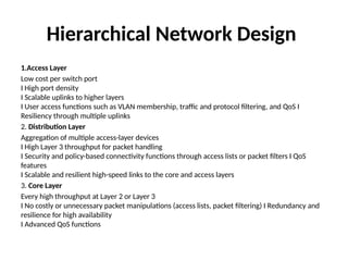
1.AccessLayer
Low cost per switch port
I High port density
I Scalable uplinks to higher layers
I User access functions such as VLAN membership, traffic and protocol filtering, and QoS I
Resiliency through multiple uplinks
2. Distribution Layer
Aggregation of multiple access-layer devices
I High Layer 3 throughput for packet handling
I Security and policy-based connectivity functions through access lists or packet filters I QoS
features
I Scalable and resilient high-speed links to the core and access layers
3. Core Layer
Every high throughput at Layer 2 or Layer 3
I No costly or unnecessary packet manipulations (access lists, packet filtering) I Redundancy and
resilience for high availability
I Advanced QoS functions
3.
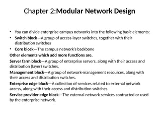
Chapter 2:Modular NetworkDesign
• You can divide enterprise campus networks into the following basic elements:
• Switch block—A group of access-layer switches, together with their
distribution switches
• Core block—The campus network’s backbone
Other elements which add more functions are.
Server farm block—A group of enterprise servers, along with their access and
distribution (layer) switches.
Management block—A group of network-management resources, along with
their access and distribution switches.
Enterprise edge block—A collection of services related to external network
access, along with their access and distribution switches.
Service provider edge block—The external network services contracted or used
by the enterprise network.
4.
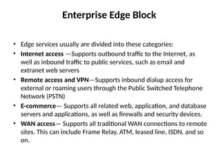
Enterprise Edge Block
•Edge services usually are divided into these categories:
• Internet access —Supports outbound traffic to the Internet, as
well as inbound traffic to public services, such as email and
extranet web servers
• Remote access and VPN—Supports inbound dialup access for
external or roaming users through the Public Switched Telephone
Network (PSTN)
• E-commerce— Supports all related web, application, and database
servers and applications, as well as firewalls and security devices.
• WAN access— Supports all traditional WAN connections to remote
sites. This can include Frame Relay, ATM, leased line, ISDN, and so
on.
5.
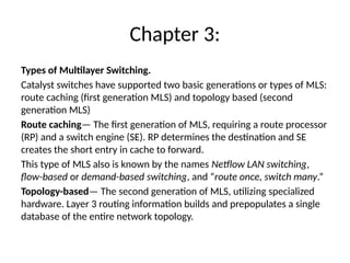
Chapter 3:
Types ofMultilayer Switching.
Catalyst switches have supported two basic generations or types of MLS:
route caching (first generation MLS) and topology based (second
generation MLS)
Route caching— The first generation of MLS, requiring a route processor
(RP) and a switch engine (SE). RP determines the destination and SE
creates the short entry in cache to forward.
This type of MLS also is known by the names Netflow LAN switching,
flow-based or demand-based switching, and “route once, switch many.”
Topology-based— The second generation of MLS, utilizing specialized
hardware. Layer 3 routing information builds and prepopulates a single
database of the entire network topology.
6.
Tables Used inSwitching
Content Addressable Memory – Switch learns the source mac and vlan id and put it
CAM table for 5 minutes and after that it removes the entry
Ternary Content Addressable Memory-ACLs can match, filter, or control specific
traffic. ll the matching process that ACLs provide is implemented in hardware.
Two components of the TCAM operation:
1. Feature Manager (FM)-After an access list has been created, it compiles, or
merges, the ACEs into entries in the TCAM table.
2. Switching Database Manager (SDM)—it configures or tunes the TCAM
partitions and apply it while transmitting the traffic.
TCAM Structure
Values- always 134 bits consisting of source and destination address and other
relevant protocols
Masks-always 134 bits and match the same value like subnet mask
Results –the numerical value which tells what to do with the packet deny or permit.
Chapter 5:VLANs andTrunks
• VLAN Membership
• Static VLAN configuration –vlan configuration is done
manually.
• Dynamic VLAN assignment – vlan configuration is done
automatically based on mac address of end users with the
help of vlan membership policy server (VMPS)
• VLANs can be scaled in the switch block by using two basic
methods:
• End-to-end VLANs- the vlan is available throughout the
network.
• Local VLANs –vlans are located locally.
9.
Vlan trunking
• Thereare two trunking protocols.
• ISL protocol-
1.It is a Cisco-proprietary method to encapsulate the vlan information.
2. It adds 26 bytes of header and 4 bytes of trailer where The trailer contains a
cyclic redundancy check (CRC) value to ensure the data integrity
• 802.1Q protocol-
1.It is open standard.
2.It adds 4 bytes just after source address to encapsulate the vlan ID.
3.The first two bytes are used as a TPID (tag protocol identifier ) with value of
0x8100 to identify the 802.1Q.
4.Remaining two bytes are used for TCI (tag control information)
TCI 16 bits = 3 bits priority field, 1 bit CFI (Canonical format indicator) whether this
is a Ethernet mac or token ring, last 12 bits are for VLAN ID to indicate the source of
the vlan.
10.
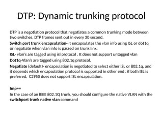
DTP: Dynamic trunkingprotocol
DTP is a negotiation protocol that negotiates a common trunking mode between
two switches. DTP frames sent out in every 30 second.
Switch port trunk encapsulation- it encapsulates the vlan info using ISL or dot1q
or negotiate when vlan info is passed on trunk link.
ISL- vlan’s are tagged using isl protocol . It does not support untagged vlan
Dot1q-Vlan’s are tagged using 802.1q protocol.
Negotiate (default)- encapsulation is negotiated to select either ISL or 802.1q, and
it depends which encapsulation protocol is supported in other end , if both ISL is
preferred. C2950 does not support ISL encapsulation.
Imp==
In the case of an IEEE 802.1Q trunk, you should configure the native VLAN with the
switchport trunk native vlan command
11.
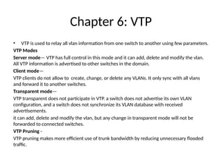
Chapter 6: VTP
•VTP is used to relay all vlan information from one switch to another using few parameters.
VTP Modes
Server mode— VTP has full control in this mode and it can add, delete and modify the vlan.
All VTP information is advertised to other switches in the domain.
Client mode—
VTP clients do not allow to create, change, or delete any VLANs. It only sync with all vlans
and forward it to another switches.
Transparent mode—
VTP transparent does not participate in VTP. a switch does not advertise its own VLAN
configuration, and a switch does not synchronize its VLAN database with received
advertisements.
it can add, delete and modify the vlan, but any change in transparent mode will not be
forwarded to connected switches.
VTP Pruning -
VTP pruning makes more efficient use of trunk bandwidth by reducing unnecessary flooded
traffic.
12.
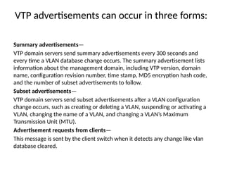
VTP advertisements canoccur in three forms:
Summary advertisements—
VTP domain servers send summary advertisements every 300 seconds and
every time a VLAN database change occurs. The summary advertisement lists
information about the management domain, including VTP version, domain
name, configuration revision number, time stamp, MD5 encryption hash code,
and the number of subset advertisements to follow.
Subset advertisements—
VTP domain servers send subset advertisements after a VLAN configuration
change occurs. such as creating or deleting a VLAN, suspending or activating a
VLAN, changing the name of a VLAN, and changing a VLAN’s Maximum
Transmission Unit (MTU).
Advertisement requests from clients—
This message is sent by the client switch when it detects any change like vlan
database cleared.
13.
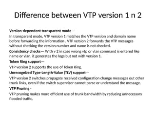
Difference between VTPversion 1 n 2
Version-dependent transparent mode—
In transparent mode, VTP version 1 matches the VTP version and domain name
before forwarding the information . VTP version 2 forwards the VTP messages
without checking the version number and name is not checked.
Consistency checks— With v 2 in case wrong vtp or vlan command is entered like
name or vlan, it generates the logs but not with version 1.
Token Ring support—
VTP version 2 supports the use of Token Ring.
Unrecognized Type-Length-Value (TLV) support—
VTP version 2 switches propagate received configuration change messages out other
trunk links, even if the switch supervisor cannot parse or understand the message.
VTP Pruning -
VTP pruning makes more efficient use of trunk bandwidth by reducing unnecessary
flooded traffic.
14.
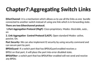
Chapter7:Aggregating Switch Links
EtherChannel-it is a mechanism which allows us to use all the links as one bundle
connected to another switch instead of using one link which is in forwarding state.
There are two Etherchannel protocol.
1.Port Aggregation Protocol (PAgP)- Cisco proprietary. Modes -Desirable, auto ,
on
2. Link Aggregation Control Protocol (LACP). Open standard Modes- active,
passive, On.
Port Security- We can also implement l2 security by using security command and
can secure port by port.
BPDUGuard- If a switch port that has BPDUGuard enabled receives a
BPDU on that port, it will place the port into error disabled state.
BPDUFilter- a switch port that has BPDUFilter enabled will not send and receive
any BPDU.
15.
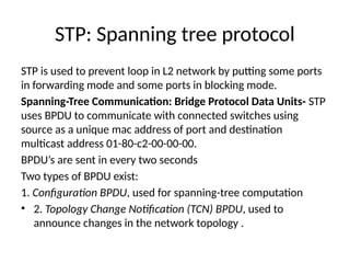
STP: Spanning treeprotocol
STP is used to prevent loop in L2 network by putting some ports
in forwarding mode and some ports in blocking mode.
Spanning-Tree Communication: Bridge Protocol Data Units- STP
uses BPDU to communicate with connected switches using
source as a unique mac address of port and destination
multicast address 01-80-c2-00-00-00.
BPDU’s are sent in every two seconds
Two types of BPDU exist:
1. Configuration BPDU, used for spanning-tree computation
• 2. Topology Change Notification (TCN) BPDU, used to
announce changes in the network topology .
16.
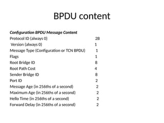
BPDU content
Configuration BPDUMessage Content
Protocol ID (always 0) 2B
Version (always 0) 1
Message Type (Configuration or TCN BPDU) 1
Flags 1
Root Bridge ID 8
Root Path Cost 4
Sender Bridge ID 8
Port ID 2
Message Age (in 256ths of a second) 2
Maximum Age (in 256ths of a second) 2
Hello Time (in 256ths of a second) 2
Forward Delay (in 256ths of a second) 2
17.
STP Continued
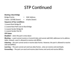
Electing aRoot Bridge
Bridge Priority + MAC Address
2 bytes (32768) (lower) + 6 bytes (lower)
Sequence of four conditions:
1.Lowest Root Bridge ID
2. Lowest Root Path Cost to Root Bridge
3. Lowest Sender Bridge ID
4. Lowest Sender Port ID
STP States
Disabled— when the port is shut down
Blocking— a port cannot receive or transmit data and cannot add MAC addresses to its address
table. Instead, a port is allowed to receive only BPDUs
Listening— the port cannot send or receive data frames. However, the port is allowed to receive
and send BPDUs
Learning— The port cannot yet send any data frames , only can receive and send bpdu
Forwarding— The port can send and receive data frames and send and receive BPDUs.
18.
STP Timers
Hello Time—2 seconds
Forward Delay— The time interval that a switch port spends in both the
Listening and Learning states. The default value is 15 seconds.
Max (maximum) Age— The time interval that a switch stores a BPDU before
discarding it. The default Max Age value is 20 seconds.
Direct Topology Changes: A direct topology change is one that can be
detected on a switch interface. For example, ifa trunk link suddenly goes
down, the switch on each end of the link can immediately detect a link failure.
Indirect Topology Changes:The link status at each switch stays up, but
something between them has failed or is filtering traffic.
Insignificant Topology Changes: with the addition of a user PC on access-
layer switch Catalyst C.
19.
Types of STP
CommonSpanning Tree: The IEEE 802.1Q standard specifies how VLANs are to be trunked
between switches. It also specifies only a single instance of STP that encompasses all VLANs.
This instance is referred to as the Common Spanning Tree(CST). All CST BPDUs are
transmitted over trunk links using the native VLAN with untagged frames. It uses 802.1Q as
a trunking protocol.
• No capability of load balance,
Per-VLAN Spanning Tree: It is a cisco proprietary and operates a separate instance of STP
for each individual VLAN. This allows the STP on each VLAN to be configured independently,
offering better performance and tuning for specific conditions.
• Better performance , Load balancing possible
• PVST requires the use of Cisco Inter-Switch Link (ISL) trunking encapsulation between
switches.
• PVST and CST require different trunking method, so BPDU’s are never exchanged
between stp types.
Per-VLAN Spanning Tree Plus: Cisco proprietary, that allows devices to interoperate with
both PVST and CST.
Redundant Link Convergence
•Port Fast: Enables fast connectivity to be established on access-
layer switch port to workstations that are booting.
• Uplink Fast:Enables fast-uplink failover on an access-layer switch
when dual up links are connected into the distribution layer
• Backbone Fast:Enables fast convergence in the network
backbone or core layer switches after a spanning-tree topology
change occurs.
• Switch(config)# spanning-tree portfast default
• Switch(config)# spanning-tree uplinkfast[max-update-rate pkts-
per-second]
• Switch(config)# spanning-tree backbonefast
22.
Chapter9:Protecting the STPTopology
Protecting Against Unexpected BPDUs:
Root Guard: controls where candidate root bridges can be connected and found on a
network. If another switch advertises a superior BPDU, or one with a better bridge ID,
on a port where Root Guard is enabled, As long as the superior BPDUs are being
received on the port, the port will be kept in the root-inconsistent STP state. No data
can be sent or received in that state, but the switch can listen to BPDUs received on
the port to detect a new root advertising itself. When the superior BPDUs no longer
are received, the port is cycled through the normal STP states to return to normal
use.
Switch(config-if)# spanning-tree guard root
Switch# show spanning-tree inconsistentports
BPDU Guard: It protects the switch ports that have Port Fast enabled. If any BPDU is
received on a port where BPDU Guard is enabled, that port immediately is put into
the errdisable state.
Switch(config)# spanning-tree portfast bpduguard default
23.
Protecting Against SuddenLoss of BPDUs
Loop Guard: In the case of blocking port where
BPDSs are received only, if not receiving the
bpdu, The blocking port will assume that there is
no STP switch and no need to block the port,
and transition it to forwarding and end of
creating the loop.
To prevent the loop
24.
Chapter 13:Layer 3High Availability
Approaches to providing router redundancy:
• Hot Standby Router Protocol (HSRP)
• Virtual Router Redundancy Protocol (VRRP)
• Gateway Load Balancing Protocol (GLBP)
HSRP Overview: Basically, each of the routers that provides redundancy for a given
gateway address is assigned to a common HSRP group. One router is elected as the
primary, or active, HSRP router; another is elected as the stand by HSRP router; and all
the others remain in the listen HSRP state. The routers exchange HSRP hello messages at
regular intervals so that they can remain aware of each other’s existence and that of the
active router.
1. HSRP is a Cisco-proprietary protocol
2. HSRP sends its hello messages to the multicast destination 224.0.0.2 (“all routers”)
using UDP port 1985.
3. Group number can be assigned from 0 to 255
4. Hellos are sent every 3 seconds, hold time timer 10 sec, three times of hello
25.
HSRP Continued
Switch(config-if)# standbygrouptimers[msec] hello[msec] holdtime
5. Preemption is disabled by default.
6. HSRP supports two types of authentication , Plain text and MD5.
Switch(config-if)# standby group authentication string
Switch(config-if)# standby groupauthentication md5 key-string[0 |7] string
7. HSRP supports tracking where it can track the interfaces and if any tracking
interface is going down it will reduce the priority.
HSRP Router Election: HSRP election is based on a priority value (0 to 255) By
default, the priority is 100. The router with the highest priority value (255 is
highest) becomes the active router for the group. If all router priorities are equal or
set to the default value, the router with the highest IP address on the HSRP
interface becomes the active router.
Switch(config-if)# standby grouppriority priority
Switch(config-if)# standby 1 priority 20
26.
Switch(config-if)# standby groupipip address[secondary]
State sequence:
1.Disabled, init, Listen, speak, standby, active
HSRP defines a special MAC address of the form 0000.0c07.acxx, where xx represents the
HSRP group number as a two-digit hex value.
Configuring an HSRP Group on a Switch:
CatalystA(config)# interface vlan 50
CatalystA(config-if)# ip address 192.168.1.10 255.255.255.0
CatalystA(config-if)# standby 1 priority 200
CatalystA(config-if)# standby 1 preempt
CatalystA(config-if)# standby 1 ip 192.168.1.1
Load Balancing with HSRP:
• Two group can be sued to load balance the traffic One group assigns an active router to
one switch, The other group assigns another active router to the other switch.
Router# show standby[brief] [vlan vlan-id | type mod/num]
27.
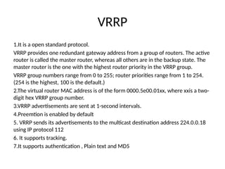
VRRP
1.It is aopen standard protocol.
VRRP provides one redundant gateway address from a group of routers. The active
router is called the master router, whereas all others are in the backup state. The
master router is the one with the highest router priority in the VRRP group.
VRRP group numbers range from 0 to 255; router priorities range from 1 to 254.
(254 is the highest, 100 is the default.)
2.The virtual router MAC address is of the form 0000.5e00.01xx, where xxis a two-
digit hex VRRP group number.
3.VRRP advertisements are sent at 1-second intervals.
4.Preemtion is enabled by default
5. VRRP sends its advertisements to the multicast destination address 224.0.0.18
using IP protocol 112
6. It supports tracking.
7.It supports authentication , Plain text and MD5
28.
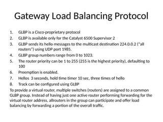
Gateway Load BalancingProtocol
1. GLBP is a Cisco-proprietary protocol
2. GLBP is available only for the Catalyst 6500 Supervisor 2
3. GLBP sends its hello messages to the multicast destination 224.0.0.2 (“all
routers”) using UDP port 1985.
4. GLBP group numbers range from 0 to 1023.
5. The router priority can be 1 to 255 (255 is the highest priority), defaulting to
100
6. Preemption is enabled.
7. Hellos 3 seconds, hold time timer 10 sec, three times of hello
8. Track can be configured using GLBP
To provide a virtual router, multiple switches (routers) are assigned to a common
GLBP group. Instead of having just one active router performing forwarding for the
virtual router address, allrouters in the group can participate and offer load
balancing by forwarding a portion of the overall traffic.
29.
Active Virtual Gateway:
Thetrick behind this load balancing lies in the GLBP group. One router is
elected the active virtual gateway(AVG). This router has the highest priority
value, or the highest IP address in the group
Active Virtual Gateway:
Each router participating in the GLBP group can become an AVF
The virtual MAC addresses always have the form 0007.b4xx.xxyy. The 16-
bit value denoted by xx.xx represents six zero bits followed by a 10-bit
GLBP group number. The 8-bit yy value is the virtual forwarder number.
Switch(config-if)# glbp grouppriority level
Switch(config-if)# glbp grouppreempt[delay minimum seconds]
Switch(config-if)# glbp grouptimers[msec] hellotime[msec] holdtime
30.
GLBP Load Balancing:
GLBPLoad Balancing: load-balancing methods.
Round robin—Each new ARP request for the virtual router address receives the
next
available virtual MAC address in reply.
Weighted—The GLBP group interface’s weighting value determines the proportion
of traffic that should be sent to that AVF. A higher weighting results in more
frequent ARP replies
Host dependent—Each client that generates an ARP request for the virtual router
address always receives the same virtual MAC address in reply. This method is used
if the clients have a need for a consistent gateway MAC address.
Switch(config-if)# glbp groupload-balancing[round-robin |weighted |host-
dependent]
Switch(config-if)# glbp groupip[ip-address[secondary]]
31.
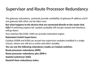
Supervisor and RouteProcessor Redundancy
The gateway redundancy protocols provide availability of gateway IP address and if
one gateway fails other can be taken over.
But what happens to the devices that are connected directly to the router that
fails? If switching engines fail packets probably will not get routed and interfaces
will go down.
Few switches like 6500, 4500 can provide redundant engine.
Redundant Switch Supervisors:
Catalyst 4500R and 6500 can accept two supervisor modules installed in a single
chassis, where one will act as active and other standby.
You can use the following redundancy modes on Catalyst switches:
Route processor redundancy (RPR):
Route processor redundancy plus (RPR+)
Stateful switchover (SSO)
Router# show redundancy states
32.
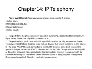
Chapter14: IP Telephony
•Power over Ethernet: Four way we can provide the power to IP phones
1 In line power
2.POE (802.3af) (802.3at)
3.Power patch panel
4.In line coupler
1. The port starts the phone-discovery algorithm by sending a special Fast Link Pulse (FLP)
signal to any device that might be connected to it.
2. The port waits to see if the special FLP signal is forwarded back by a connected device.
The only devices that are designed to do this are devices that expect to receive in-line power.
3. If a Cisco 79xx IP Phone is connected to the 10/100 Ethernet port, it will forward the
special FLP signal back to the 10/100 Ethernet port on the Cisco Catalyst switch. It is capable
of doing this because it has a special relay that connects its Ethernet receive pair with its
Ethernet transmit pair. This relay is closed when no power is being supplied to the phone.
Once power is supplied, this relay remains in an open state.
33.
POE
4. Now thatthe Cisco Catalyst switch has determined that it needs to power the port (the
special FLP signal was received back from the attached Cisco IP Phone), the Network
Management Processor (NMP) is queried to determine if there is any power available to
power the IP phone. Since the NMP does not know how much power the Cisco IP Phone
will need, it uses the configured default power allocation. Later on it will adjust this
allocation based on what the attached Cisco IP Phone tells the switch it really needs.
5. The port then provides power to the Cisco IP Phone over pairs 1 and 2 as a common mode
current.
6. The port is taken out of phone-discovery mode and changed to normal 10/100 Ethernet
auto-negotiation mode.
7. The instant that the switch applies power to the port, the relay inside the phone opens and
power begins to flow to the Cisco IP Phone.
8. At this point a 'wait for link' timer in the switch starts also. The phone has five seconds to
establish link integrity on its Ethernet port. If the switch does not detect link integrity on the
port within five seconds, it will shut off power to the port and start the phone-discovery
process all over again. The switch has to wait at least five seconds so that the switch has
enough time to detect all devices.
34.
POE
9. If theswitch detects a link within the five second window, it will
continue to supply power to the Cisco IP Phone until it detects a link down
event.
10. Once the phone has booted up, it will send a CDP message with a
Type, Length, Value object (TLV) that tells the switch how much power
it really needs. The NMP sees this and adjusts the power allocation for
the port accordingly.
Configuring PoE:
Switch(config)# interface type mod/num
Switch(config-if)# power inline{auto[max milli-watts] |static[max milli-
watts] |never}
Verifying PoE:
Switch# show power inline[type mod/num]
35.
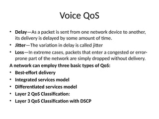
Voice QoS
• Delay—Asa packet is sent from one network device to another,
its delivery is delayed by some amount of time.
• Jitter—The variation in delay is called jitter
• Loss—In extreme cases, packets that enter a congested or error-
prone part of the network are simply dropped without delivery.
A network can employ three basic types of QoS:
• Best-effort delivery
• Integrated services model
• Differentiated services model
• Layer 2 QoS Classification:
• Layer 3 QoS Classification with DSCP
36.
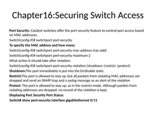
Chapter16:Securing Switch Access
PortSecurity: Catalyst switches offer the port security feature to control port access based
on MAC addresses.
Switch(config-if)# switchport port-security
To specify the MAC address and how many:
Switch(config-if)# switchport port-security mac-address mac-addr
Switch(config-if)# switchport port-security maximum 2
What action it should take after violation:
Switch(config-if)# switchport port-security violation {shutdown |restrict |protect}
Shutdown:The port immediately is put into the Errdisable state.
Restrict:The port is allowed to stay up, but all packets from violating MAC addresses are
dropped and send an SNMP trap and a syslog message as an alert of the violation
Protect: The port is allowed to stay up, as in the restrict mode. Although packets from
violating addresses are dropped, no record of the violation is kept.
Displaying Port Security Port Status:
Switch# show port-security interface gigabitethernet 0/11
37.
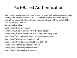
Port-Based Authentication
Switches cansupport port-based authentication, using AAA authentication and port
security. This is based on the IEEE 802.1x standard. When it is enabled, a switch
port will not pass any traffic until a user has authenticated with the switch. 802.1x
EAPOL is a Layer 2 protocol
802.1x Configuration:
Switch(config)# aaa new-model
Switch(config)# radius-server host 10.1.1.1 key BigSecret
Switch(config)# radius-server host 10.1.1.2 key AnotherBigSecret
Switch(config)# aaa authentication dot1x default group radius
Switch(config)# dot1x system-auth-control
Switch(config)# interface range FastEthernet0/1 – 40
Switch(config-if)# switchport access vlan 10
Switch(config-if)# switchport mode access
Switch(config-if)# dot1x port-control auto
38.
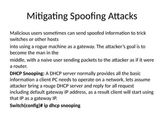
Mitigating Spoofing Attacks
Malicioususers sometimes can send spoofed information to trick
switches or other hosts
into using a rogue machine as a gateway. The attacker’s goal is to
become the man in the
middle, with a naive user sending packets to the attacker as if it were
a router.
DHCP Snooping: A DHCP server normally provides all the basic
information a client PC needs to operate on a network, lets assume
attacker bring a rouge DHCP server and reply for all request
including default gateway IP address, as a result client will start using
that IP as a gateway IP.
Switch(config)# ip dhcp snooping
39.
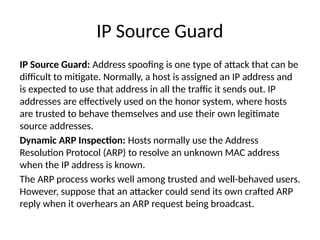
IP Source Guard
IPSource Guard: Address spoofing is one type of attack that can be
difficult to mitigate. Normally, a host is assigned an IP address and
is expected to use that address in all the traffic it sends out. IP
addresses are effectively used on the honor system, where hosts
are trusted to behave themselves and use their own legitimate
source addresses.
Dynamic ARP Inspection: Hosts normally use the Address
Resolution Protocol (ARP) to resolve an unknown MAC address
when the IP address is known.
The ARP process works well among trusted and well-behaved users.
However, suppose that an attacker could send its own crafted ARP
reply when it overhears an ARP request being broadcast.
40.
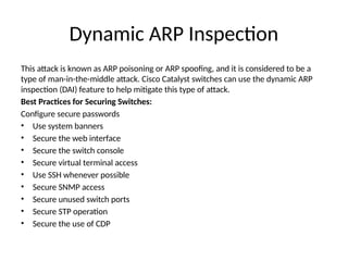
Dynamic ARP Inspection
Thisattack is known as ARP poisoning or ARP spoofing, and it is considered to be a
type of man-in-the-middle attack. Cisco Catalyst switches can use the dynamic ARP
inspection (DAI) feature to help mitigate this type of attack.
Best Practices for Securing Switches:
Configure secure passwords
• Use system banners
• Secure the web interface
• Secure the switch console
• Secure virtual terminal access
• Use SSH whenever possible
• Secure SNMP access
• Secure unused switch ports
• Secure STP operation
• Secure the use of CDP
41.
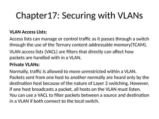
Chapter17: Securing withVLANs
VLAN Access Lists:
Access lists can manage or control traffic as it passes through a switch
through the use of the Ternary content addressable memory(TCAM).
VLAN access lists (VACL) are filters that directly can affect how
packets are handled with in a VLAN.
Private VLANs:
Normally, traffic is allowed to move unrestricted within a VLAN.
Packets sent from one host to another normally are heard only by the
destination host because of the nature of Layer 2 switching. However,
if one host broadcasts a packet, all hosts on the VLAN must listen.
You can use a VACL to filter packets between a source and destination
in a VLAN if both connect to the local switch.
42.
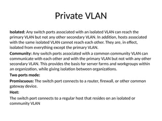
Private VLAN
Isolated: Anyswitch ports associated with an isolated VLAN can reach the
primary VLAN but not any other secondary VLAN. In addition, hosts associated
with the same isolated VLAN cannot reach each other. They are, in effect,
isolated from everything except the primary VLAN.
Community: Any switch ports associated with a common community VLAN can
communicate with each other and with the primary VLAN but not with any other
secondary VLAN. This provides the basis for server farms and workgroups within
an organization, while giving isolation between organizations.
Two ports mode:
Promiscuous: The switch port connects to a router, firewall, or other common
gateway device.
Host:
The switch port connects to a regular host that resides on an isolated or
community VLAN
43.
Securing VLAN Trunks
SwitchSpoofing: This kind of spoofing happens when Switch port is connects
to PC, Suppose that a switch port is left to its default configuration, in which
the trunking mode is auto. Normally, the switch port would wait to be asked
by another switch in the auto or on mode to become a trunk in this case A
malicious user, however, might exploit the use of DTP and attempt to negotiate
a trunk with the switch port. This makes the PC appear to be another switch;
in effect, the PC is spoofing a switch.
The solution to this situation is to hard code every switch port to have an
expected and controlled behavior.
VLAN Hopping: When securing VLAN trunks, also consider the potential for an
exploit called VLAN hopping. Here, an attacker positioned on one access VLAN
can craft and send frames with spoofed 802.1Q tags so that the packet
payloads ultimately appear on a totally different VLAN, all without the use of a
router.
#28 The load balancing is provided completely through the use of virtual router MAC addresses in ARP replies returned to the clients. As a client sends an ARP request looking for the virtual router address,
GLBP sends back an ARP reply with the virtual MAC address of a selected router in the group. The result is that all clients use the same gateway address but have differing MAC addresses for it.
#31 RPR: The redundant supervisor is only partially booted and initialized. When the active module fails, the standby module must reload every other module in the switch and then initialize all the supervisor functions.
RPRP: The redundant supervisor is booted, allowing the supervisor and route engine to initialize. No Layer 2 or Layer 3 functions
are started, however. When the active module fails, the standby module finishes initializing without reloading other switch modules. This allows switch ports to retain their state.
SSO: The redundant supervisor is fully booted and initialized. Both the startup and running configuration contents are synchronized between the supervisor modules. Layer 2 information is maintained on both supervisors so that hardware switching can continue during a failover. The state of the switch interfaces is also maintained on both supervisors so that links don’t flap during a failover.
#35 Best effort delivery: A network that just forwards packets in the order they were received has no real QoS.
Switches and routers then make their “best effort” to deliver packets as quickly as possible, with no regard for the type of traffic or the need for priority service.
Integrated Services Model: in this model data is prioritize, the Resource Reservation Protocol (RSVP) was developed as the
mechanism for scheduling and reserving adequate path bandwidth for an application.
Differentiated Services Model: the IntServ model does not scale very well when many sources are trying to compete with each other to reserve end-to-end bandwidth. Another approach is the differentiated services (DiffServ) model, which permits each network device to handle packets on an individual basis. Each router or switch can be configured with QoS policies to follow, and forwarding decisions are made accordingly.
Note: DiffServ requires no advance reservations; QoS is handled dynamically, in a distributed fashion. In other words, whereas IntServ applies QoS on a per-flow basis, DiffServ applies it on a per-hop basis to a whole group of similar flows.
Layer 2 frames : themselves have no mechanism to indicate the priority or importance of their contents. One frame looks just as important as another. Therefore, a Layer 2 switch can forward frames only according to a best-effort delivery.
The two trunk encapsulations handle CoS differently: 1. IEEE 802.1Q 2. Inter-Switch Link (ISL)
#37 Step 1. Enable AAA on the switch.
Switch(config)# aaa new-model
Step 2. Define external RADIUS servers.
Switch(config)#radius-serverhost{hostname | ip-address}[key string]
Step 3. Define the authentication method for 802.1x.
Using the following command causes all RADIUS authentication servers that are defined on the switch to be used for 802.1x authentication:
Switch(config)# aaa authentication dot1x default group radius
Step 4. Enable 802.1x on the switch:
Switch(config)# dot1x system-auth-control
Step 5. Configure each switch port that will use 802.1x:
Switch(config)# interface type mod/num
Switch(config-if)# dot1x port-control{force-authorized |force-unauthorized |auto}
force-authorized—The port is forced to always authorize any connected client. No authentication is necessary.
force-unauthorized—The port is forced to never authorize any connected client. As a result, the port cannot move to the authorized state to pass traffic to a connected client.
auto—Theportusesan802.1xexchangetomovefromtheunauthorized totheauthorizedstate,ifsuccessful.Thisrequiresan802.1x-capable applicationontheclientPC.
#38 Suppose that an attacker could bring up a rogue DHCP server on a machine in the same subnet as that same client PC. Now when the client broadcasts its DHCP request, the
rogue server could send a carefully crafted DHCP reply with its own IP address substituted as the default gateway. When the client receives the reply, it begins using the spoofed gateway address. Packets
destined for addresses outside the local subnet then go to the attacker’s machine first. The attacker can forward the packets to the correct destination, but in the meantime, it can ex-amine every packet that it intercepts. In effect, this becomes a type of man-in-the-middle attack; the attacker is wedged into the path and the client doesn’t realize it
Cisco Catalyst switches can use the DHCP snooping feature to help mitigate this type of attack.
When DHCP snooping is enabled, switch ports are categorized as trusted or untrusted. Legitimate DHCP servers can be found on trusted ports, whereas all other hosts sit behind untrusted ports.
DHCP Snooping Configuration:
Switch(config)# ip dhcp snooping
Switch(config)# ip dhcp snooping vlan 104
Switch(config)# interface range fastethernet 0/35 – 36
Switch(config-if)# ip dhcp snooping limit rate 3
Switch(config-if)# interface gigabitethernet 0/1
Switch(config-if)# ip dhcp snooping trust
Switch# show ip dhcp snooping
#39 PC can use its legitimate address, or it can begin to use spoofed addresses borrowed from other hosts or used at random.
Routers or Layer3 devices can perform some simple tests to detect spoofed source addresses in packets passing through.
Cisco Catalyst switches can use the IP source guard feature to detect and suppress address spoofing attacks
IP Source Guard does this by making use of the DHCP snooping database and static IP source binding entries. If DHCP snooping is configured and enabled, the switch learns the MAC and IP addresses of hosts that use DHCP. Packets arriving on a switch port can be tested for one of the following conditions:
The source IP address must be identical to the IP address learned by DHCP snooping or a static entry. A dynamic port ACL is used to filter traffic. The switch automatically creates this ACL, adds the learned source IP address to the ACL, and applies the ACL to the interface where the address is learned.
The source MAC address must be identical to the MAC address learned on the switch port and by DHCP snooping. Port security is used to filter traffic.
Note: If the address is something other than the one learned or statically configured, the switch drops the packet.
Switch(config)# ip source binding mac-addressvlan vlan-id ip-addressinterface type mod/num
Enable IP source guard on interfaces
Switch(config)# interface type mod/num
Switch(config-if)# ip verify source[port-security]
#40 DAI works much like DHCP snooping. All switch ports are classified as trusted or untrusted. The switch intercepts and inspects all ARP packets that arrive on an untrusted port; no inspection is done on trusted ports.
When an ARP reply is received on an untrusted port, the switch checks the MAC and IP addresses reported in the reply packet against known and trusted values.
A switch can gather trusted ARP information from statically configured entries or from dynamic entries in the DHCP snooping database.
In the latter case, DHCP snooping must be enabled in addition to DAI.
If an ARP reply contains invalid information or values that conflict with entries in the trusted database, it is dropped and a log message is generated.
Configuring DAI to Validate ARP Replies:
Switch(config)# ip arp inspection vlan 104
Switch(config)# arp access-list StaticARP
Switch(config-acl)# permit ip host 192.168.1.10 mac host 0006.5b02.a841
Switch(config-acl)# exit
Switch(config)# ip arp inspection filter StaticARP vlan 104
Switch(config)# interface gigabitethernet 0/1
Switch(config-if)# ip arp inspection trust
#41 VACL Configuration:
VACLs are configured as a VLAN access map in much the same format as a route map.
Switch(config)# vlan access-map map-name[sequence-number]
Next, define the matching conditions that identify the traffic to be filtered. Matching is performed by access lists (IP, IPX, or MAC address ACLs),
Switch(config-access-map)# match ip address{acl-number | acl-name}
Switch(config-access-map)# match ipx address{acl-number | acl-name}
Switch(config-access-map)# match mac address acl-name
Define the action with the following access map configuration command:
Switch(config-access-map)# action{drop |forward[capture] |redirect type mod/num}
Finally, you must apply the VACL to a VLAN using the following global configuration
command:
Switch(config)# vlan filter map-namevlan-list vlan-list
Private VLANs (PVLAN) solve this problem on Catalyst switches. In a nutshell, a normal, or primary, VLAN can be logically associated with special unidirectional, or secondary, VLANs. Hosts associated with a secondary VLAN can communicate with ports on the primary VLAN (a router, for example), but not with another secondary VLAN. A secondary VLAN is configured as one of the following types:
#42 You must configure each physical switch port that uses a private VLAN with a VLAN association. You also must define the port with one of the following modes:
All secondary VLANs must be associated with one primary VLAN to set up the unidirectional relationship. Private VLANs are configured using special cases of regular VLANs. However, the VLAN Trunking Protocol (VTP) does not pass any information about the private VLAN configuration.
Therefore, private VLANs are only locally signifi- cant to a switch. Each of the private VLANs must be configured locally on each switch that interconnects them.
Configure the Private VLANs
To configure a private VLAN, begin by defining any secondary VLANs that are needed for isolation using the following configuration commands:
Switch(config)# vlan vlan-id
Switch(config-vlan)# private-vlan{isolated |community}
The secondary VLAN can be an isolated VLAN (no connectivity between isolated ports) or a community VLAN (connectivity between member ports).
Now define the primary VLAN that will provide the underlying private VLAN connectivity using the following configuration commands:
Switch(config)# vlan vlan-id
Switch(config-vlan)# private-vlan primary
Switch(config-vlan)# private-vlan association{secondary-vlan-list |add secondary-vlan-list |remove secondary-vlan-list}
Associate Ports with Private VLANs
Switch(config-if)# switchport mode private-vlan{host |promiscuous}
![STP Configuration
• Switch(config)# spanning-tree vlan vlan-id
• Switch (config-if)# spanning-tree vlan vlan-id
• Switch(config)# spanning-tree extend system-id
• Switch(config)# spanning-tree vlan vlan-listpriority bridge-priority
• Switch(config)# spanning-tree vlan vlan-idroot{primary |secondary}
[diameter diameter]
• Switch(config-if)# spanning-tree[vlan vlan-list] port-priority port-priority
• Switch (config-if)# spanning-tree[vlan vlan-id] cost cost
• Switch(config-if)# spanning-tree[vlan vlan-list] port-priority port-priority
Manually Configuring STP Timers
• Switch(config)# spanning-tree[vlan vlan-id] hello-time seconds
• Switch(config)# spanning-tree[vlan vlan-id] forward-time seconds
• Switch(config)# spanning-tree[vlan vlan-id] max-age seconds](https://image.slidesharecdn.com/enterprisenetworkdesign-250402043857-7ce87044/85/Enterprise-network-design-multi-layer-network-and-security-pptx-20-320.jpg)
![Redundant Link Convergence
• Port Fast: Enables fast connectivity to be established on access-
layer switch port to workstations that are booting.
• Uplink Fast:Enables fast-uplink failover on an access-layer switch
when dual up links are connected into the distribution layer
• Backbone Fast:Enables fast convergence in the network
backbone or core layer switches after a spanning-tree topology
change occurs.
• Switch(config)# spanning-tree portfast default
• Switch(config)# spanning-tree uplinkfast[max-update-rate pkts-
per-second]
• Switch(config)# spanning-tree backbonefast](https://image.slidesharecdn.com/enterprisenetworkdesign-250402043857-7ce87044/85/Enterprise-network-design-multi-layer-network-and-security-pptx-21-320.jpg)

![HSRP Continued
Switch(config-if)# standby grouptimers[msec] hello[msec] holdtime
5. Preemption is disabled by default.
6. HSRP supports two types of authentication , Plain text and MD5.
Switch(config-if)# standby group authentication string
Switch(config-if)# standby groupauthentication md5 key-string[0 |7] string
7. HSRP supports tracking where it can track the interfaces and if any tracking
interface is going down it will reduce the priority.
HSRP Router Election: HSRP election is based on a priority value (0 to 255) By
default, the priority is 100. The router with the highest priority value (255 is
highest) becomes the active router for the group. If all router priorities are equal or
set to the default value, the router with the highest IP address on the HSRP
interface becomes the active router.
Switch(config-if)# standby grouppriority priority
Switch(config-if)# standby 1 priority 20](https://image.slidesharecdn.com/enterprisenetworkdesign-250402043857-7ce87044/85/Enterprise-network-design-multi-layer-network-and-security-pptx-25-320.jpg)
![Switch(config-if)# standby groupip ip address[secondary]
State sequence:
1.Disabled, init, Listen, speak, standby, active
HSRP defines a special MAC address of the form 0000.0c07.acxx, where xx represents the
HSRP group number as a two-digit hex value.
Configuring an HSRP Group on a Switch:
CatalystA(config)# interface vlan 50
CatalystA(config-if)# ip address 192.168.1.10 255.255.255.0
CatalystA(config-if)# standby 1 priority 200
CatalystA(config-if)# standby 1 preempt
CatalystA(config-if)# standby 1 ip 192.168.1.1
Load Balancing with HSRP:
• Two group can be sued to load balance the traffic One group assigns an active router to
one switch, The other group assigns another active router to the other switch.
Router# show standby[brief] [vlan vlan-id | type mod/num]](https://image.slidesharecdn.com/enterprisenetworkdesign-250402043857-7ce87044/85/Enterprise-network-design-multi-layer-network-and-security-pptx-26-320.jpg)
![Active Virtual Gateway:
The trick behind this load balancing lies in the GLBP group. One router is
elected the active virtual gateway(AVG). This router has the highest priority
value, or the highest IP address in the group
Active Virtual Gateway:
Each router participating in the GLBP group can become an AVF
The virtual MAC addresses always have the form 0007.b4xx.xxyy. The 16-
bit value denoted by xx.xx represents six zero bits followed by a 10-bit
GLBP group number. The 8-bit yy value is the virtual forwarder number.
Switch(config-if)# glbp grouppriority level
Switch(config-if)# glbp grouppreempt[delay minimum seconds]
Switch(config-if)# glbp grouptimers[msec] hellotime[msec] holdtime](https://image.slidesharecdn.com/enterprisenetworkdesign-250402043857-7ce87044/85/Enterprise-network-design-multi-layer-network-and-security-pptx-29-320.jpg)
![GLBP Load Balancing:
GLBP Load Balancing: load-balancing methods.
Round robin—Each new ARP request for the virtual router address receives the
next
available virtual MAC address in reply.
Weighted—The GLBP group interface’s weighting value determines the proportion
of traffic that should be sent to that AVF. A higher weighting results in more
frequent ARP replies
Host dependent—Each client that generates an ARP request for the virtual router
address always receives the same virtual MAC address in reply. This method is used
if the clients have a need for a consistent gateway MAC address.
Switch(config-if)# glbp groupload-balancing[round-robin |weighted |host-
dependent]
Switch(config-if)# glbp groupip[ip-address[secondary]]](https://image.slidesharecdn.com/enterprisenetworkdesign-250402043857-7ce87044/85/Enterprise-network-design-multi-layer-network-and-security-pptx-30-320.jpg)
![POE
9. If the switch detects a link within the five second window, it will
continue to supply power to the Cisco IP Phone until it detects a link down
event.
10. Once the phone has booted up, it will send a CDP message with a
Type, Length, Value object (TLV) that tells the switch how much power
it really needs. The NMP sees this and adjusts the power allocation for
the port accordingly.
Configuring PoE:
Switch(config)# interface type mod/num
Switch(config-if)# power inline{auto[max milli-watts] |static[max milli-
watts] |never}
Verifying PoE:
Switch# show power inline[type mod/num]](https://image.slidesharecdn.com/enterprisenetworkdesign-250402043857-7ce87044/85/Enterprise-network-design-multi-layer-network-and-security-pptx-34-320.jpg)