This document provides examples of calculations related to rigid pavement design, including:
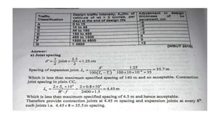
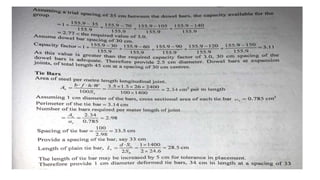
1) Calculating the spacing between contraction joints for plain and reinforced concrete slabs of varying thickness and reinforcement.
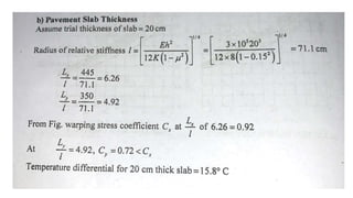
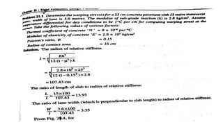
2) Computing the radius of relative stiffness for concrete slabs over subgrade, given slab properties and subgrade modulus.
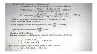
3) Determining wheel load stresses, dowel bar sizing and spacing, equivalent resisting section radius, and contraction joint tensile stress.
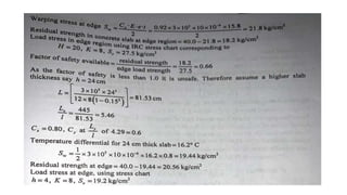
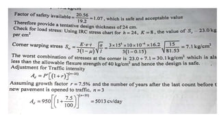
4) Summarizing the process for designing a rigid pavement using Westergaard wheel load and wrapping stress equations at the slab edge.
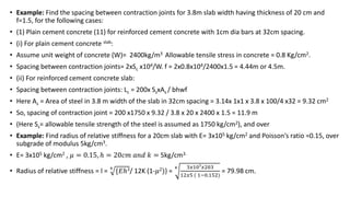
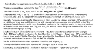
![• Example: Using data given below determine:
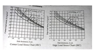
• (a) Edge and Corner load stresses by Westergaard equation.
• Wheel load P= 5200kg, pavement thickness h= 18cm, Poisson ratio of concrete 𝜇 = 0.15,
radius of contact area ‘a’ = 15cm, Modulus of elasticity of concrete= E= 3.0x10⁵ kg/cm2 ,
modulus of subgrade reaction k= 6.0 kg/cm2
• Solution: Radius of relative stiffness; l = 4
{𝐸ℎ3/ 12K (1-𝜇2)} =
4 3.0𝑥105𝑥183
12𝑥6.0 ( 1−0.152
)
= 70.6 cm.
• Equivalent radius of resisting section is given by a/h = 15/18 = 0.833 <1.724
• Therefore equivalent radius of the resisting section= b = 1.6𝑎2 + ℎ2 - 0.675h =
1.6 𝑋 152 + 182 - (0.675x18) = 14cm.
• Edge load stress, σe =
0.572 𝑃
ℎ2 {4 log10 (l/b) +0.359 } =
0.572 𝑥 5200
182 {4 log10 (70.6/14) +0.359}
= 29.1 kg/ cm2
• Corner load Stress σc =
3𝑃
ℎ2 [ 1- (
𝑎√2
𝑙
) 0.6 =
3𝑥5200
182 [ 1- (
15√2
70.6
) 0.6 ] = 24.75 kg/ cm2](https://image.slidesharecdn.com/sumsonrigidpavement-220525144228-3e9e6220/85/Sums-on-Rigid-Pavement-Design-3-320.jpg)
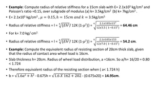
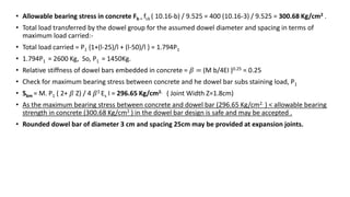
![• Example: Using data given below, calculate wheel load stresses at:- ( a) Interior (b) Edge ( c) Corner regions of a
cement concrete pavement using westargaard stress equation and also determine the probable location of crack is
likely to develop due to corner loading. Wheel load =5200Kg. E= 3.0x10⁵ kg/cm2 , 𝜇 = 0.15, ℎ = 18𝑐𝑚 𝑎𝑛𝑑 𝑘 =
6.0kg/cm3 Radius of contact area= 15cm.
• Radius of relative stiffness = l = 4
{𝐸ℎ3/ 12K (1-𝜇2)} =
4 3𝑥105𝑥183
12𝑥6 ( 1−0.152
)
= 70.6 cm.
• Equivalent radius of the resisting section= b = 1.6𝑎2 + ℎ2 - 0.675h = 1.6 𝑋 152 + 182 - (0.675x18) = 14cm.
• ( a/h = 15/18 = 0.833 < 1.74)
• Interior load stress, σi =
0.316 𝑃
ℎ2 {4 log10 (l/b) +1.069 } =
0.316 𝑥 5200
182 {4 log10 (70.6/14) +1.069 }= 19.68kg/cm2 .
• Edge load stress, σe =
0.572 𝑃
ℎ2 {4 log10 (l/b) +0.359 } =
0.572 𝑥 5200
182 {4 log10 (70.6/14) +0.359} = 29.1 kg/ cm2
• Corner load Stress σc =
3𝑃
ℎ2 [ 1- (
𝑎√2
𝑙
) 0.6 =
3𝑥5200
182 [ 1- (
15√2
70.6
)] 0.6 = 24.75 kg/ cm2
• Location where corner load cracks develop: location where the crack is likely to develop due to corner loading,
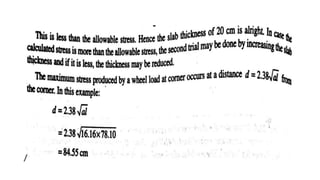
the distance from the corner of the slab, x = 2.58 (a.l)1/2 = 2.58x( 15x 70.6) ½ = 83.96 cm = 84 cm.
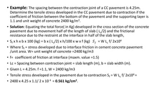
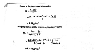
• Example: Determine the wrapping streses at interior, edge and corner of 30cm thick cement concrete pavement
with transverse joint at 5m interval and longitudinal joints at 3.6 m interval. The modulus of subgrade reaction =
𝑘 = 6.9kg/cm3 and radius of loaded area is 15 cm. Assume maximum temperature differential during day to be 0.6
0C per cm slab thickness ( for wrapping stresses at interior and edge) and maximum temperature differential at 0.4
0C per cm slab thickness during night ( for wrapping stress at corner). Other data are E= 3.0x10⁵ kg/cm2 , 𝜇 =
0.15, ∝ = 10𝑥10-6 per 0C.](https://image.slidesharecdn.com/sumsonrigidpavement-220525144228-3e9e6220/85/Sums-on-Rigid-Pavement-Design-6-320.jpg)
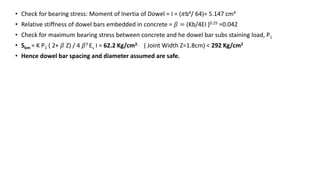
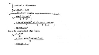
![• Given Slab thickness h= 30cm. Modulus of Elasticity E= 3.0x10⁵ kg/cm2 , Poission’s ratio =𝜇 = 0.15,
Thermal coefficient of temperature ∝ = 10𝑥10-6 per 0C. a= 15 cm. Lx= 500 cm, Ly =360 cm.
• Temperature differential during day, t1 = 0.6x 30 = 180C
• Temperature differential during night, t2 = 0.4x 30 = 120C
• Radius of relative stiffness = l = 4
{𝐸ℎ3/ 12K (1-𝜇2)} =
4 3𝑥105𝑥303
12𝑥6.9 ( 1−0.152)
= 100 cm.
• Lx /l= 500/100 = 5 , Ly / l =360/100 =3.6 , Refer to Bradbury’s Chart for wrapping stress coefficients
corresponding to Lx /l = 5 , Cx =0.75, Ly /l = 3.6 , Cy =0.4,
• Wrapping stress at interior region of the slab, during day
Sti =
E ∝ t
2
[
Cx +𝜇 Cy
1−𝜇2 ] =
3𝑥 105𝑥 10 𝑥10
−
6
𝑥18
2
[ 0.75 + 0.15x 0.4/ (1- 0.152 )= 22.4 kg/cm2
Wrapping stress at edge region of the slab, during day
Ste =
Cx E ∝ t
2
[ as it is higher than
Cy E ∝ t
2
] =
0.75𝑥 3𝑥 105𝑥 10 𝑥10
−
6
𝑥18
2
= 20.25kg/cm2
Wrapping stress at corner region of the slab, during night,
Stc =
E ∝ t
3 ( 1−𝜇 )
( a/l) ½ =
3𝑥 105𝑥 10 𝑥10
−
6
𝑥12
3 ( 1−0.15)
( 15/ 100) 1/2 = 5.47 kg/cm2](https://image.slidesharecdn.com/sumsonrigidpavement-220525144228-3e9e6220/85/Sums-on-Rigid-Pavement-Design-7-320.jpg)
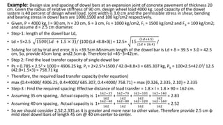
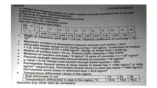
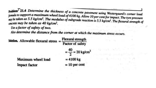
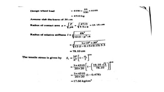
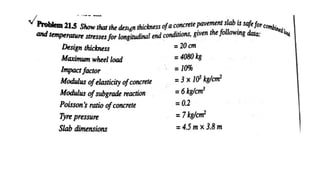
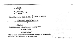
![• Example: Design a rigid pavement making use of wastergaard wheel load and wrapping stress equations at
the edge region of the slab. The design data are given below:
• Design wheel load P= 7500Kg, Contact pressure p= 7.5Kg/cm2, spacing between longitudinal joints= 3.75 m
, spacing between contraction joint= 4.2m. E= 3.0x10⁵ kg/cm2 Poisson′
s ratio, 𝜇 = 0.15, Thermal
coefficient of cc 0C ∝ = 1𝑥10-5. Flexural strength of cc = 45 kg/cm2 modulus of basecourse = 𝑘 =
30kg/cm3, Maximum temperature differential at the location for pavement thickness value of 22,24,26
and 30cm are respectively14.8,15.6,16.2,16.8 0C, Desired factor of safety with respect to load stress and
wrapping stress at edge region is 1.1 to 1.2.
• Solution: P = 7500 kg, p = 7.5Kg/cm2, therefore radius ‘a’ = √
𝑃
𝑝𝜋
= √
7500
7.5𝑥𝜋
= 17.84 cm
• Trial 1, Assume pavement thickness h=25cm, Given K= 30kg/cm3, . E= 3.0x10⁵ kg/cm2, 𝜇 = 0.15
• Radius of relative stiffness = l = 4
{𝐸ℎ3/ 12K (1-𝜇2)} =
4 3𝑥105𝑥253
12𝑥30 ( 1−0.152
)
= 60.41 cm,
• a/h = 17.84/25 = 0.7136< 1.724, Radius of the resisting section= b = 1.6𝑎2 + ℎ2 - 0.675h =
1.6 𝑋 (17.84)2 + 252 - (0.675x25) = 16.80 cm.
• Edge load stress, σe =
0.572 𝑃
ℎ2 [{4 log10 (l/b) +0.359 }] = 17.74 Kg/cm2
• For h= 25cm, temperature differential ( by interpolation) = (15.6+16.2) /2 = 15.9 0C
• Lx= 4.2m = 420cm Ly=375cm, So, wrapping stress for higher ratio = Lx/l = 420/60.41 = 6.96.](https://image.slidesharecdn.com/sumsonrigidpavement-220525144228-3e9e6220/85/Sums-on-Rigid-Pavement-Design-8-320.jpg)
![• Example: Design the dowel bars and their spacing from the following data:
• Wheel load=4000Kg, Modulus of subgrade reaction =6Kg/cm2, Modulus of Elasticity of concrete = 3x10⁵
kg/cm2, Poisson’s ratio = 0.15, Slab thickness =20cm, Joint thickness= 18mm.
• Solution: Radius of relative stiffness = l = 4
{𝐸ℎ3/ 12K (1-𝜇2)} =
4 3𝑥105𝑥203
12𝑥6 ( 1−0.152
)
= 76.42 cm,
• Allowable bearing stress in concrete Fb = fck ( 10.16-b) / 9.525 = 400 (10.16-3.2) / 9.525 = 292 Kg/cm2
• ( The Grade of concrete assumed M40 Grade and Dia of Dowel bar ( assumed) = 3.2cm)
• Assumed spacing between dowel bars = 32 cm and First dowel bar is placed at a distance=15cm from
pavement edge. Assumed length of the dowel bar=50 cm.
• Dowel bars upto a distance of 1.0x radius of relative stiffness, from the point of load application are
effective in load transfer.
• No of dowel bars participating in the load transfer when wheel load is just over the dowel bar close to the
edge of the slab = 1+ (76.42/32) = 3 dowels
• Assuming that the load transfer by the first dowel is P1 and assuming that the load on the dowel bar at a
distance of l from the first dowel to be zero, the total load transferred by the dowel bar system =
• [ 1+ (76.42-32)/76.42 + ( 76.42-64)/76.42] . P1 = 1.75 P1
• Load carried by the outer dowel bar, P1 = 4000/1.75 = 2286 Kg.](https://image.slidesharecdn.com/sumsonrigidpavement-220525144228-3e9e6220/85/Sums-on-Rigid-Pavement-Design-11-320.jpg)


![Geotechnical Engineering-II [Lec #15 & 16: Schmertmann Method]](https://cdn.slidesharecdn.com/ss_thumbnails/15-181020124920-thumbnail.jpg?width=640&height=640&fit=bounds)