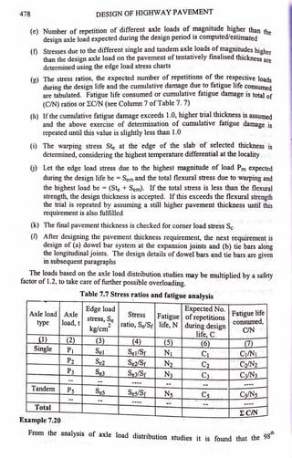
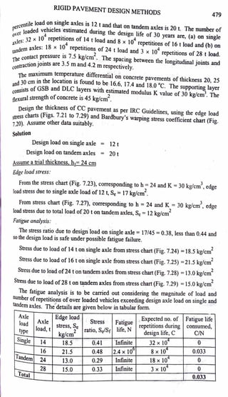
The document outlines the steps for designing the thickness of cement concrete (CC) pavement according to IRC guidelines, emphasizing parameters such as design axle load, temperature differential, and supporting layer properties. It details a trial-and-error approach to determining pavement thickness by checking stress ratios against flexural strength and cumulative fatigue damage. Additionally, the document discusses the design of dowel bars for load transfer at joints, highlighting considerations for bearing stress and structural integrity.
![480 DESIGN OF 1-llGHWAY PAVEMENT
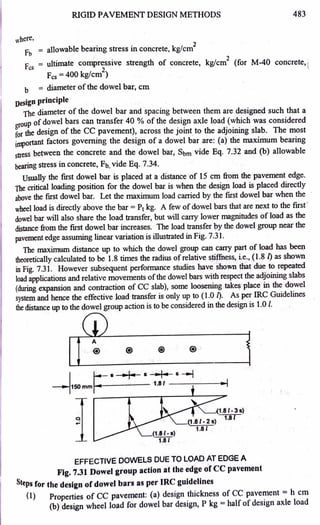
Since total fatigue life consumed or cumulative_ fati~e damag~ due ~o axle loads
exceeding design load is only 0.033 or 3.3 % of f~ttgue hfe ~e d_eSlgn t~ckness of24
cm is safe due to repeated application ofloads durmg the design hfe.
Warping stress:
Temperature differential, t for 24 cm pavement thickness (by interpolation) = 17.24 °c
Length ofslab, Lx = 4.2 m = 420 cm, thickness, h = 24 cm, K
3
= 30 kg/cm
Assuming E = 3 x 10⁵
kg/cm
2
, Poisson's ratio,µ= 0.15
Radius ofrelative stiffness, I = [ Eh3 ]
114
12K(l-µ2
)
= 58.6 cm (substituting the ~alues)
Corresponding to Lx = 420 cm, Lxf/ = 420/58.6 =7.17; from
warping stress coefficient chart (Fig. 7.20),
Cx =0.98
Corresponding to LJI = 350/58.6 = 5.97, Cy= 0.9
Considering higher ofthe two values, adopt warping stress coefficient of0.98.
Therefore maximum warping stress at pavement edge,
Ste =
Total stress
Cx Eet = (0.98 x 3 x 105
x 1 x 10-5
x 17.24)/2
2
2
= 25.34 kg/cm
Highest load stress at pavement edge · = 21.5 kg/cm
2
Total (load stress+ warping stress) at edge = 46.84 kg/cm
2
As the total stress exceeds the flexural strength of 45 kg/cm
2
, the design is to be
revised, assuming a higher pavement thickness in order to fulfil this criterion.
In trial no. 2, assume pavement thickness h = 30 cm
Radius ofrelative stiffness, (substituting the values) l = [ Eh
3
]
114
= 69.27 cm
· 12K(l-µ2)
Highest edge load stress due to single axle load of 16 t for h == 30 cm (from Fig. 7.25)
= 15.3 kg/cm
2
Temperature differential, t for pavement thickness of 30 cm (by interpolation== 18.0 °C
Lxf/ = 420/69.27 = 6.06, Cx =0.90
Maximum warping stress at edge = (0.90 x 3 x 105
x 1 x 10-s x 18.0)/2 = 24.3 kg/cm
2
Total (load stress + tarping stress) = 15.3 + 24.3 = 39.6 kg/cm2, less than flexural
strength of45 kg/cm , hence safe.](https://image.slidesharecdn.com/pd-m4-rpdesign-240619105915-3505d4f1/85/Pavement-Design-Rigid-Pavement-Design-pdf-4-320.jpg)
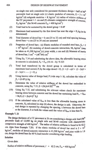
![RIGID PAVEMENT DESIGN METHODS 481
The factor of safety available for the maximum stress d t th hi h
· - 45139 6 - 1 1 ue O e g est load and
warping stress - · - • 4, may be accepted
Check for comer load stress, Sc = !~[1-(a-;2r2
]
Substituting design load P = 16 / 2 =8.0 t =8,000 kg h =30 / =69 27
3
== J(8000/ 7.5,r) = 18.43 cm ' cm, · cm,
Substituting, the values in the equation Sc= 18 4 kg/cm2 and so th d · · "
. , • e es1gn 1s sa1e.
Adopt design thickness ofCC pavement =30 cm
7.9.4 De~ign ofDowel Bars at Load Transfer Joints
Objectiv~s of dowel bars
As mentioned in Art. 7.6.3, expansion joints and construction joints are formed as
thro~gh joints acr~ss ~~ full depth of the slab. A small gap of about 20 mm is
provided at expans10~ JOmts to allow for expansion of long CC pavement slabs during
s~er seaso~. This gap or joint width helps to relieve the compressive stresses
dunng expansion and also helps to prevent buckling of the slab near the joint Steel
dowel bars are embedded at mid depth during construction as specified in the design in
order to strengthen these weak locations and to provide desired load transfer to the
adjoining slab across the joint. Though it is not considered very essential to provide
expansion joints in CC pavements at regular intervals, they should invariably be
provided wh~re the pavement is designed to abut structures like b~dges. /
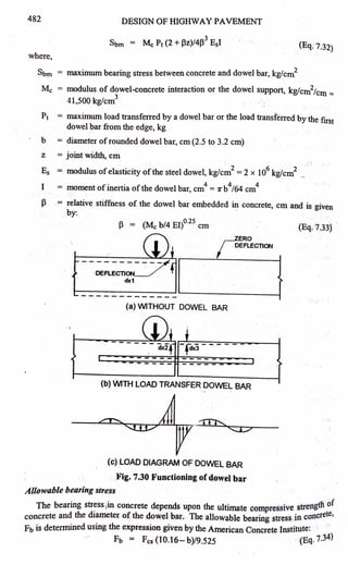
Functioning
Figure 7.30 (a) illustrates that there is no load transfer across the expansion joint
without dowel bars as each slab deflects independently under the axle load. The
functioning of an expansion joint with dowel bar is illustrated in Fig. 7.30 (b). When
wheel load is placed at the edge ofthe slab adjoining the expansion joint, a part ofthe
deflection and load are transferred across to the adjoining slab with the help ofa group
ofdowel bars. The load stress diagram in dowel bar is shown in Fig. 7.30 (c).
Rounded steel bars ofdiameter 25 to 32 mm and length about 500 mm are placed at
intervals of 250 to 300 mm as per the design. About 50 mm less t1ian half lengtli of
. the rounded steel dowel bars are embedded during concreting along one slab, so as to
develop bond with the concrete. The other halflength ofthe dowel bars (plus 50 mm)
are covered with a suitable plastic sheathing to prevent development ofbond between
the dowel bars and the concrete of the adjoining slab. This de-bonded half length of
the dowel bars can slide into the adjoining slab. The construction details are given in
Art. 8.5.5 of Chapter 8, 'Highway Construction'.
Stresses in dowel bars
The maximum bearing stress developed in the.dowel bar.and the allowable bearing
stress in cement concrete are to be considered dunng the design.
Maximum bearing stress
The bearing stress between concrete and dowel ba~ depends ~inly on diameter of
the dowel bar and spacing between them. The maximum beanng stress between the
concrete and the dowel bar is given by the equation:](https://image.slidesharecdn.com/pd-m4-rpdesign-240619105915-3505d4f1/85/Pavement-Design-Rigid-Pavement-Design-pdf-5-320.jpg)
![RIGID PAVEMENT DESIGN METHODS
485
Elastic modulus of dowel bar steel, Es = 2 x 1'06 kg/cm2,
modulus ofdowel - concrete interaction, u = 41 500 kg/ J d • • .dth
1
• "'"C , cm an Jomt w1 z = .8 cm
Design load (98t11 percentile axle load) on single axle ~ 12,000 kg
Therefore design wheel load for dowel bar design, p =
6000
kg
Total load to be sustained by dowel g.roup
= 0,4 p =0,4 X 6000
= 2400 kg
Let the maximum load s~stained by the first dowel bar near the edge = P1 kg
Assume diameter of dowel bar b = 3 ocm and sp · b
in the first trial , . acmg etween dowel bars, s =25 cm
Substituting the relevant values,
Moment of inertia of dowel bar, I = (7rb4/64) cm4 =3_
976 cm4
Allowable bearing stress in conc_
rete is calculated using Eq. 7.34
ie., Fb = Fcs (10.16- b)/9,525 = 300.7 kg/cm2
T~tal ~oad transferre~ by the dowel group for the assumed dowel diameter and
spacmg m terms of maximum load carried,
Pt = P1 {l +(/-s)//+(/-2s)//+(/ - 3s)//+---}
= Pt Y = Pt {l + (62.2-25)/62.2 + (62.2-50)/62.2} = 1.794 P1
= 2400
Pt = 2400/1.794 = 1337.8 kg
Relative stiffness of the dowel bar embedded·in concrete, p=(Mcb/4 El)o.25 cm
(substituting the relevant values from above) = 0.25
Check for maximum bearing stress between concrete and the dowel bar sustaining
load Pt(vide Eq. 7.32), Sbm = McPt (2 + Pz)/4 p3
E5I = (substituting the relevant
. 2
values from above)= 273.7 kg/cm .
As the maximum bearing stress between concrete and the dowel bar (273.7 kg/en/)
is less than the allowable bearing strength in concrete (300.7 kg/cm
2
) the dowel bar
design is safe and therefore may be accepted. Rounded dowel bars of diameter 3.0 cm
and spacing 25 cm may. be provided at expansion joints.
(Note: In case it is necessary to reduce some quantity of steel, the trial may be repeated assuming
ahigher spacing of 27 or 30 cm)
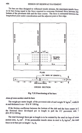
7.9.5 Design ofTie Bars at Longitudinal Joints
Objectives oftie bars
Tie bars are used across the longitudinal joints of cement concrete p_avements. Tie
bars are embedded at mid depth during concreting ensure th~ two adJacent sl~bs on
either side of the longitudinal joint to remain firmly to~et~er a~d to_prev~nt opem~g up
oftheJ·o· t S F. 7 17 and 7.32. The ]ongitudinalJomts with tie bars act as lunges
m . ee ig. . Tl . b t
and help to relieve part of warping stresses in CC pavement. 1e tie ars are no
designed to act as load tran~_fer devices.](https://image.slidesharecdn.com/pd-m4-rpdesign-240619105915-3505d4f1/85/Pavement-Design-Rigid-Pavement-Design-pdf-9-320.jpg)