1
PHILADELPHIA UNIVERSITY
Department ofCivil Engineering
Concrete & Steel Structures
(0670416)
Chapter 3-a
Flexural Analysis and Design of
Beams
Instructor:
Eng. Abdallah Odeibat
Civil Engineer, Structures , M.Sc.
12
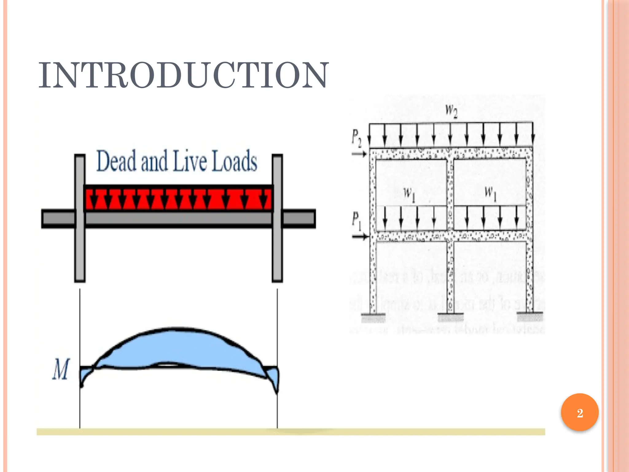
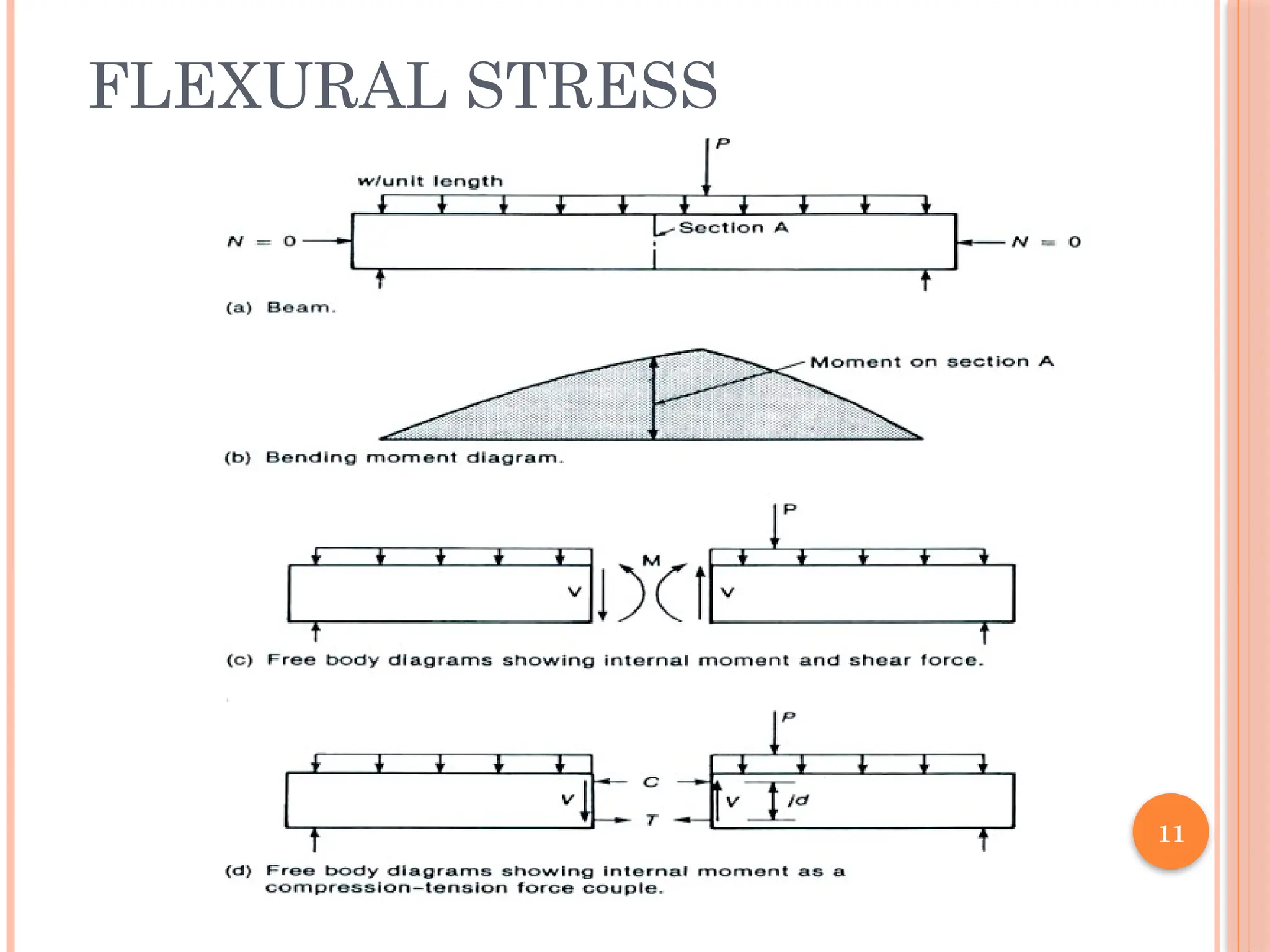
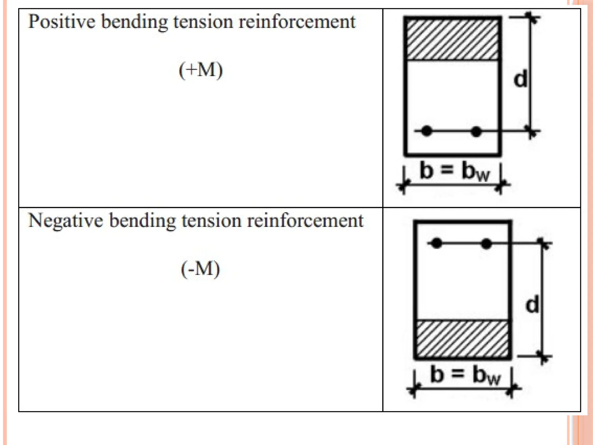
FLEXURAL STRESS
The beamis a structural member used
to support the internal moments and
shears. It would be called a beam-
column if a compressive force existed.
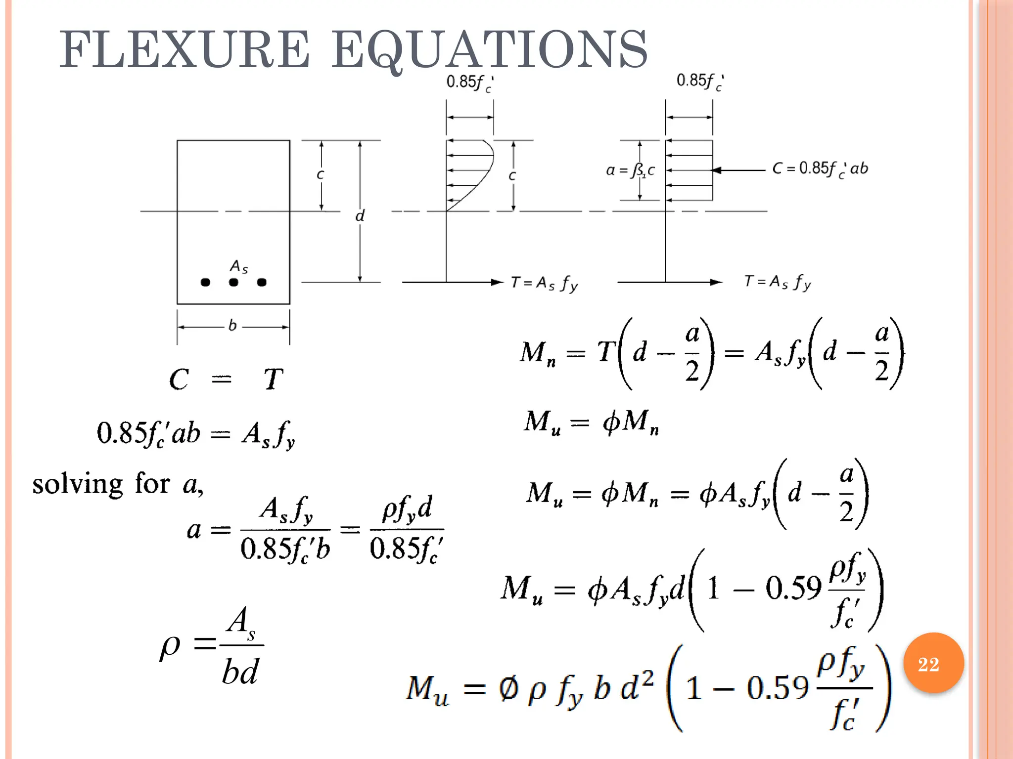
C = T
M = C*(jd)
= T*(jd)
13.
13
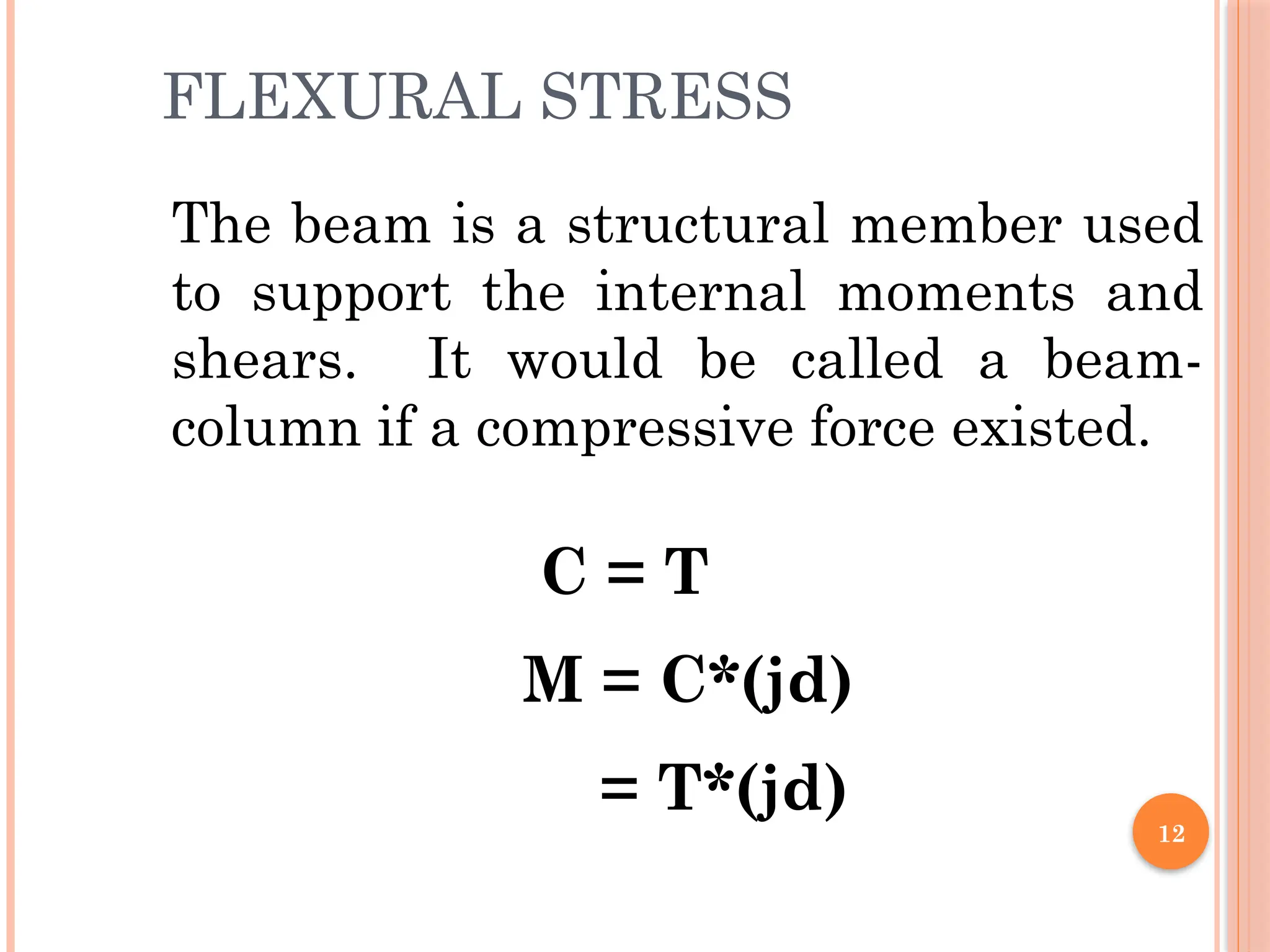
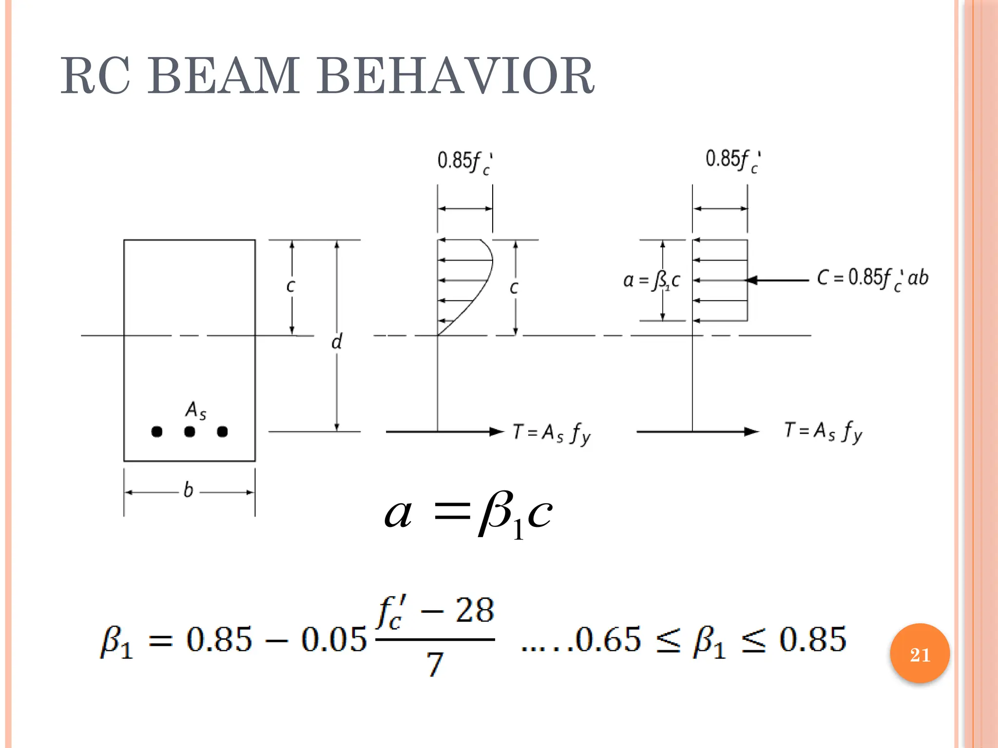
ASSUMPTIONS
Plane sectionsbefore bending remain plane under load
Strain distribution is linear in both concrete & steel and is directly
proportional to the distance from N.A.
Concrete in the tension zone is neglected in the flexural analysis & design
computation
Maximum concrete strain = 0.003 (in compression)
εc=0.003
εs = fy / Es
h d
c
0.85fc’
a a/2
d-a/2
b
C
T
14.
14
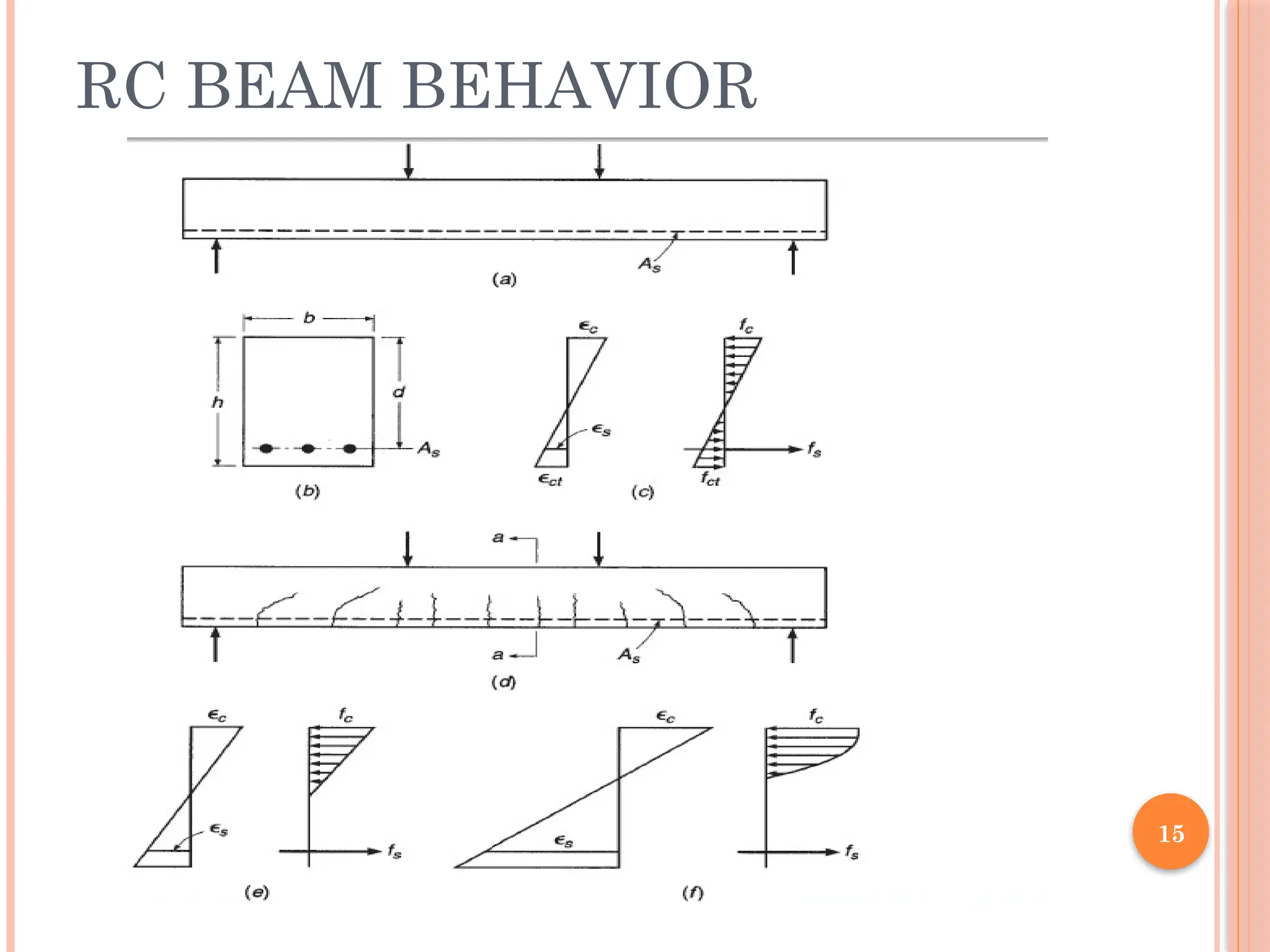
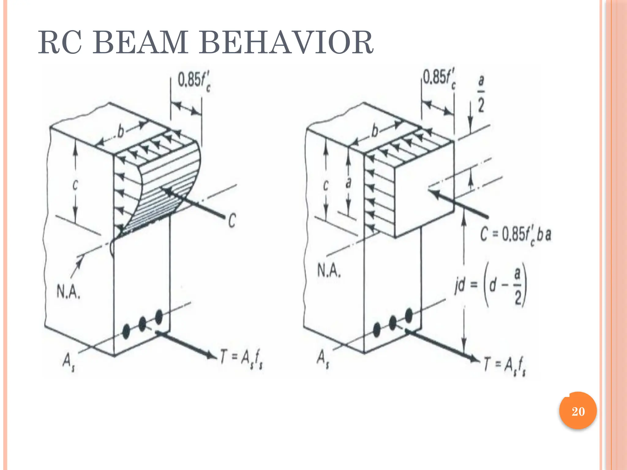
RC BEAM BEHAVIOR
Assume that a small transverse load is placed on a
concrete beam with tensile reinforcing and that load is
gradually increased in magnitude until the beam
fails. As this happen the beam will go through three
behavior stages before collapse:
1. Uncracked Concrete Stage
2. Concrete Cracked–Elastic Stresses Stage
3. Beam Failure—Ultimate-Strength Stage
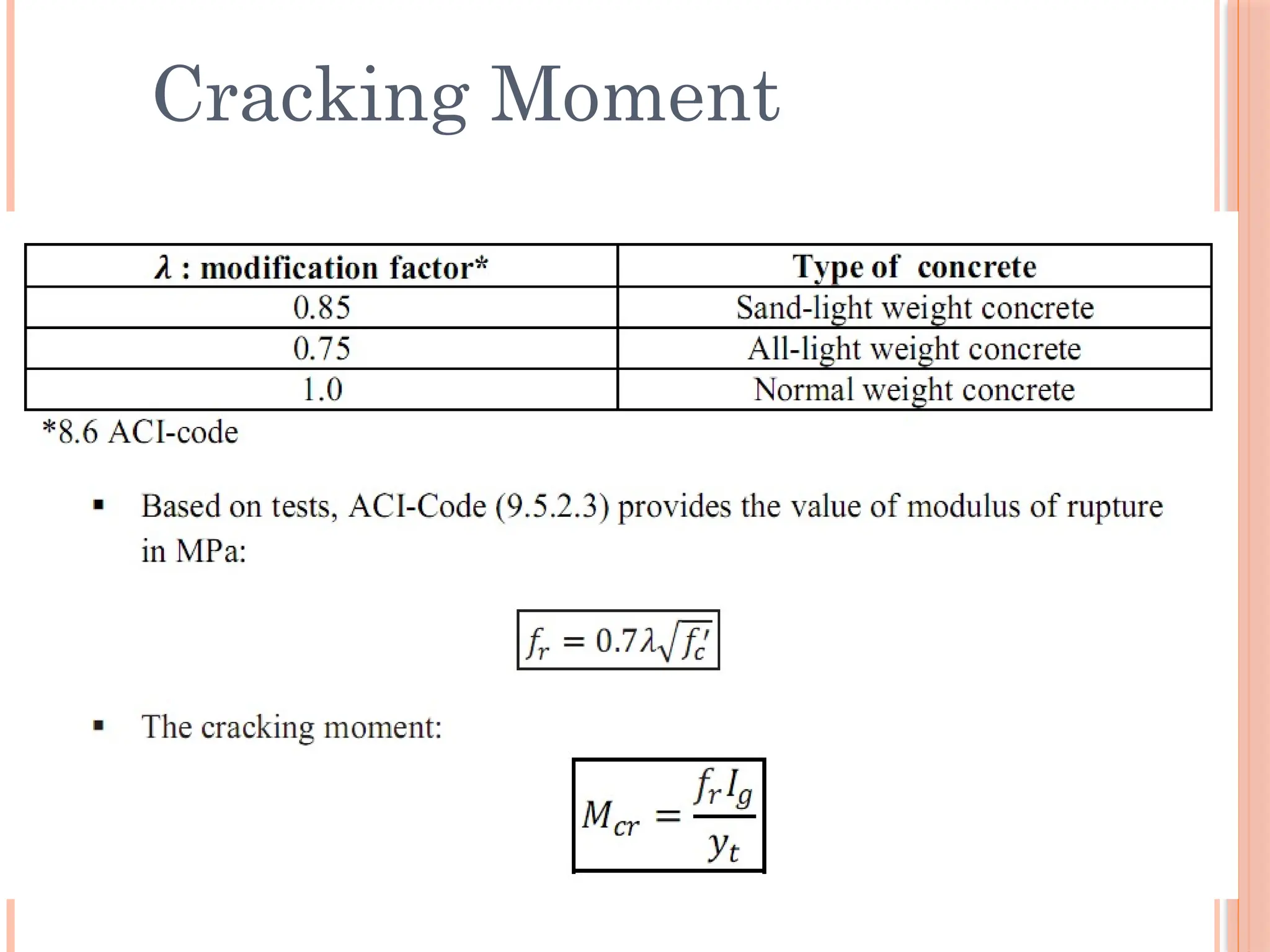
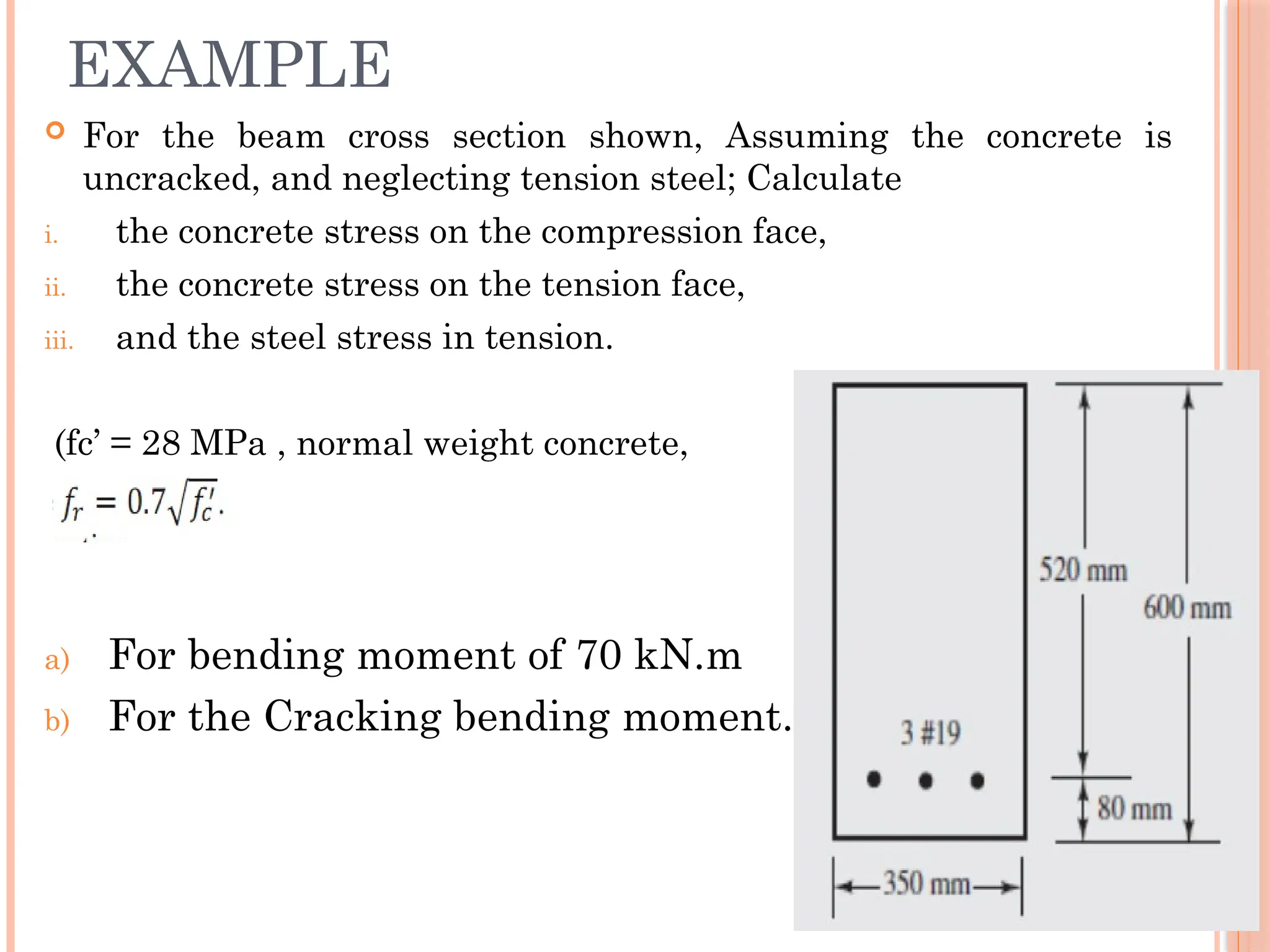
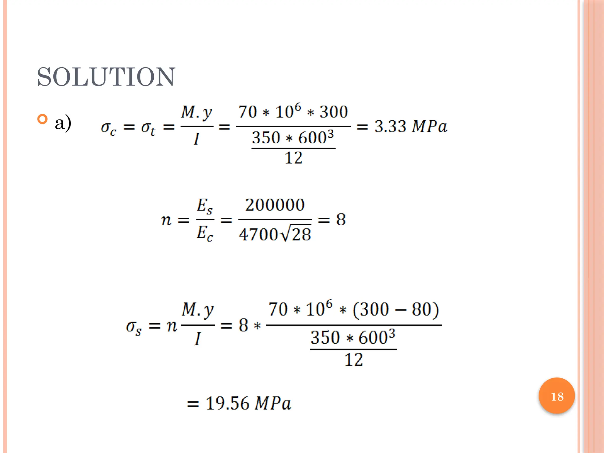
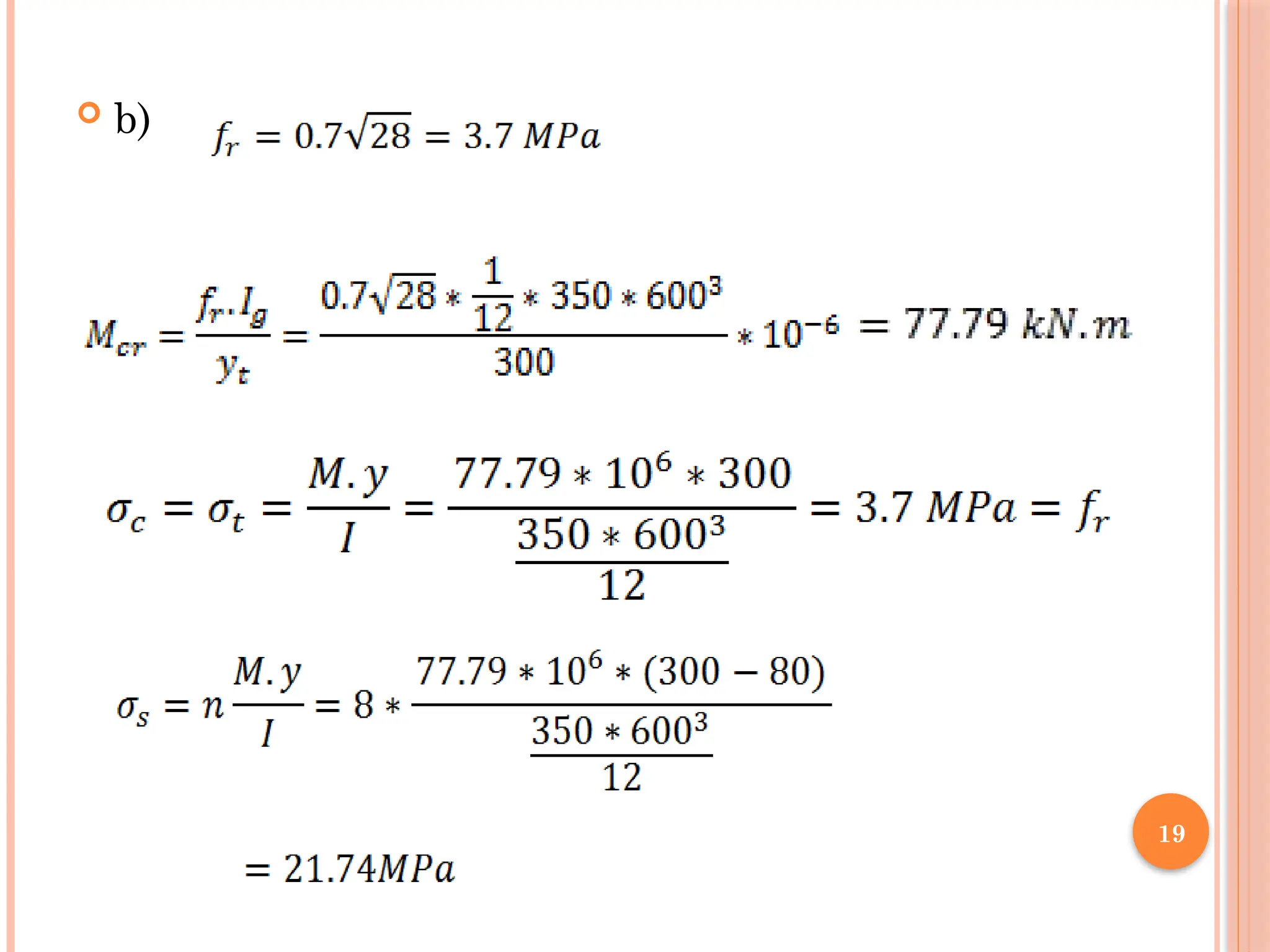
For thebeam cross section shown, Assuming the concrete is
uncracked, and neglecting tension steel; Calculate
i. the concrete stress on the compression face,
ii. the concrete stress on the tension face,
iii. and the steel stress in tension.
(fc’ = 28 MPa , normal weight concrete,
a) For bending moment of 70 kN.m
b) For the Cracking bending moment.
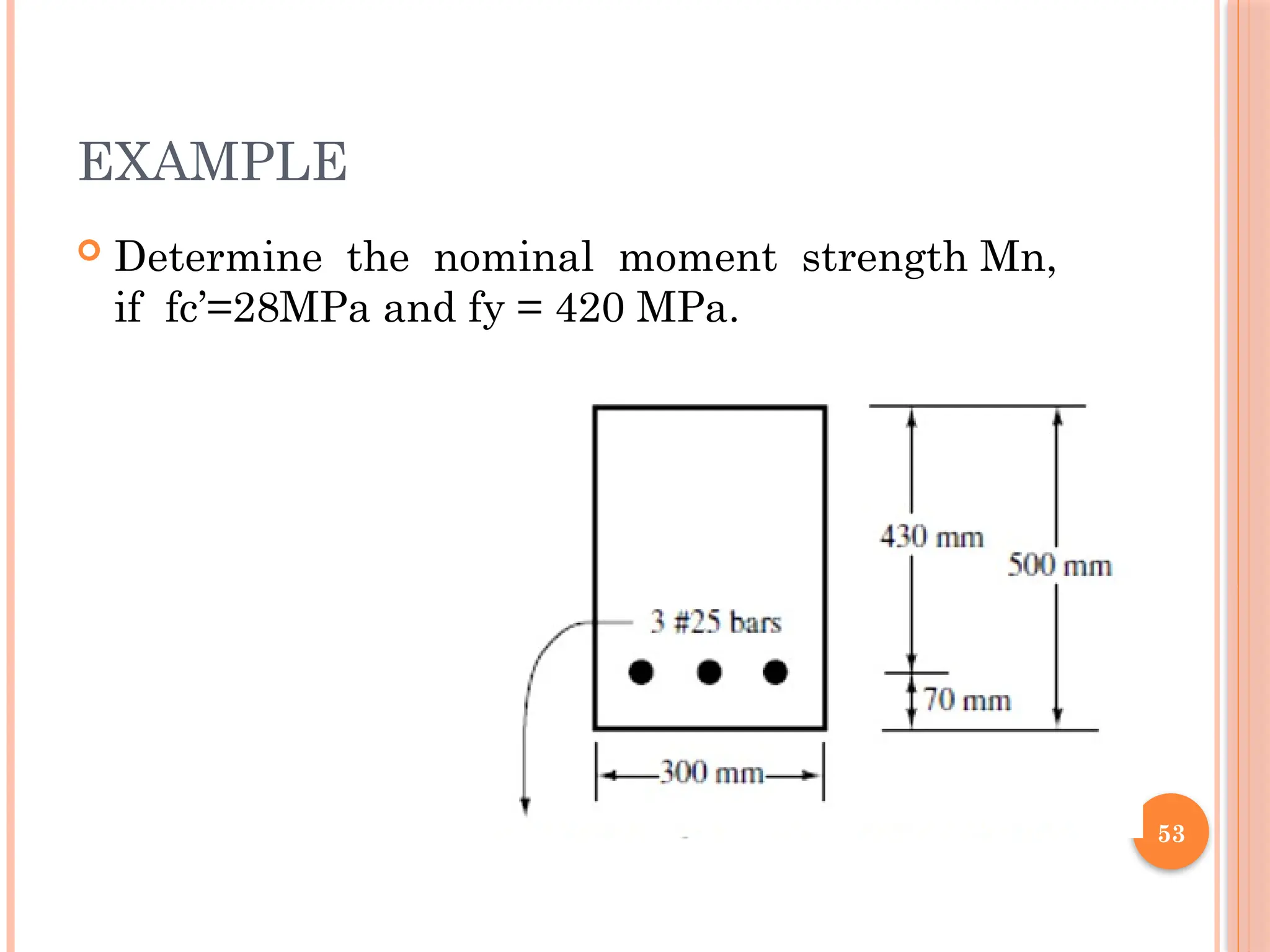
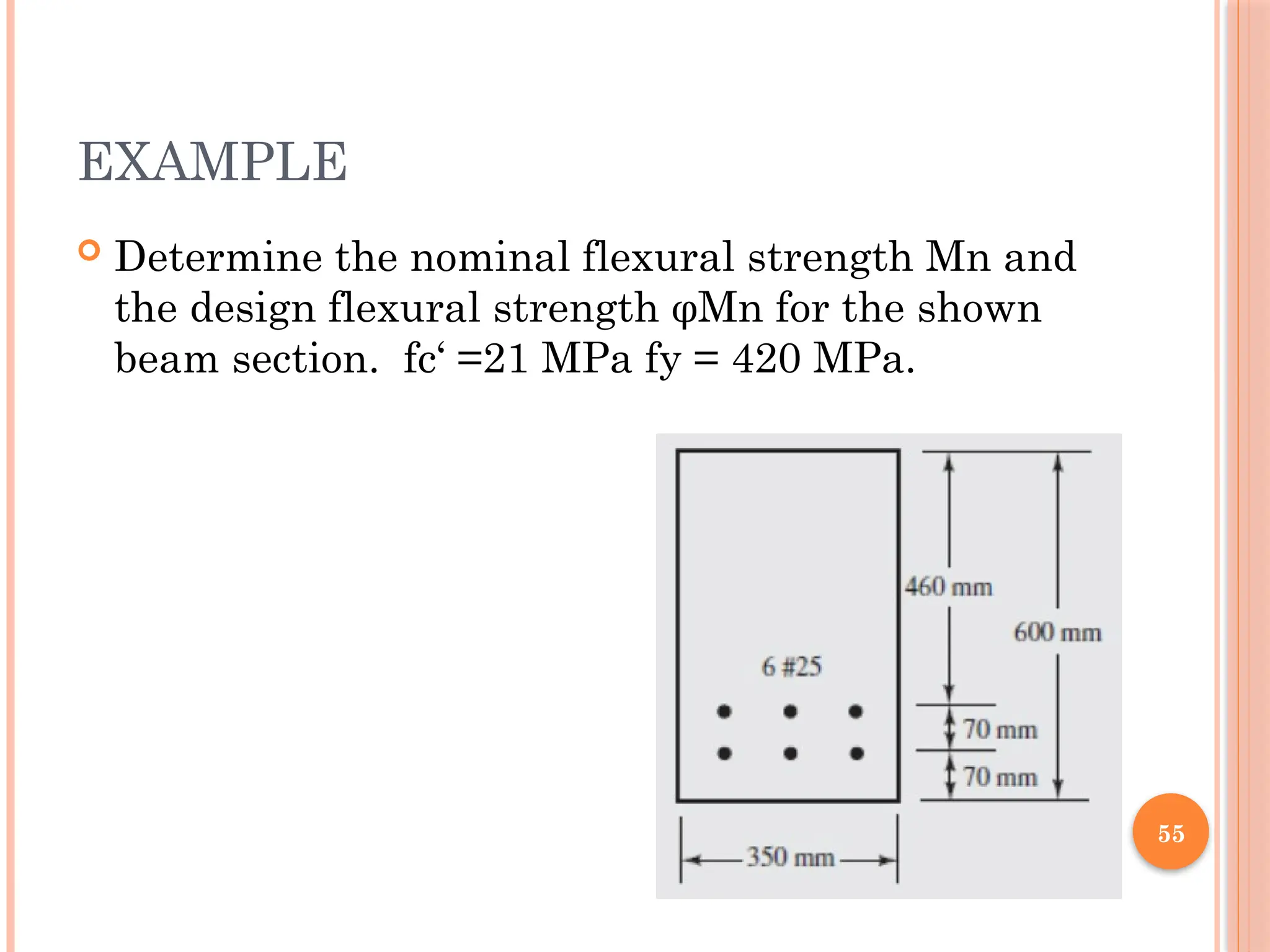
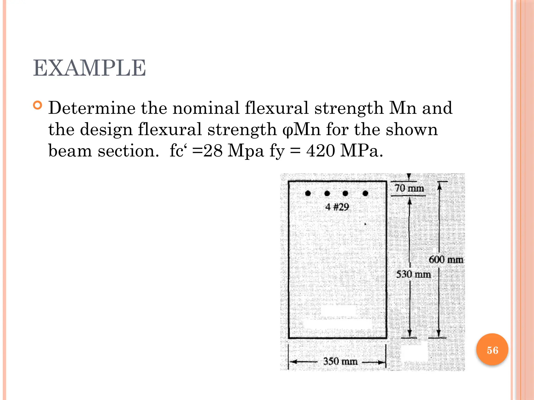
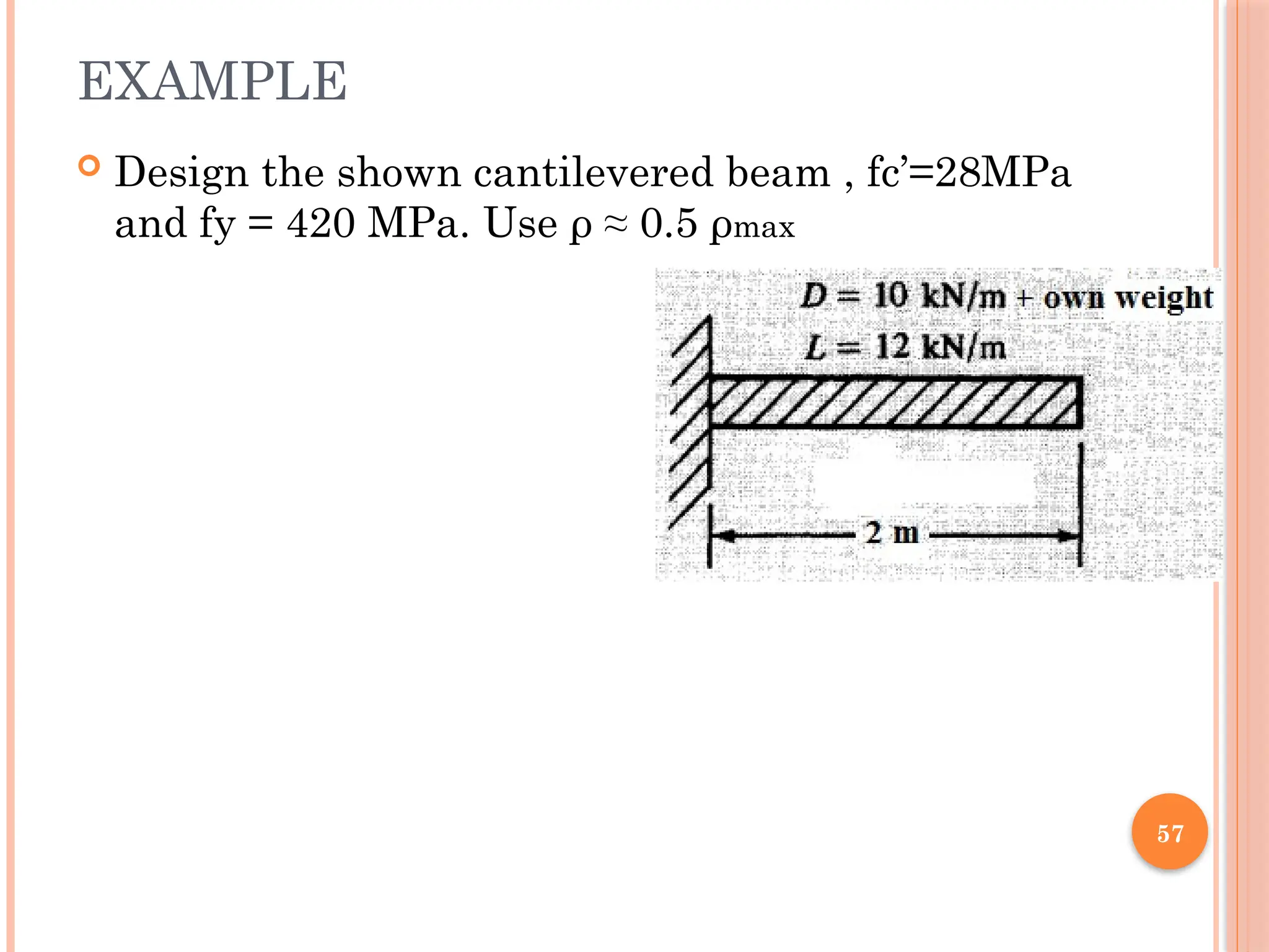
EXAMPLE
17
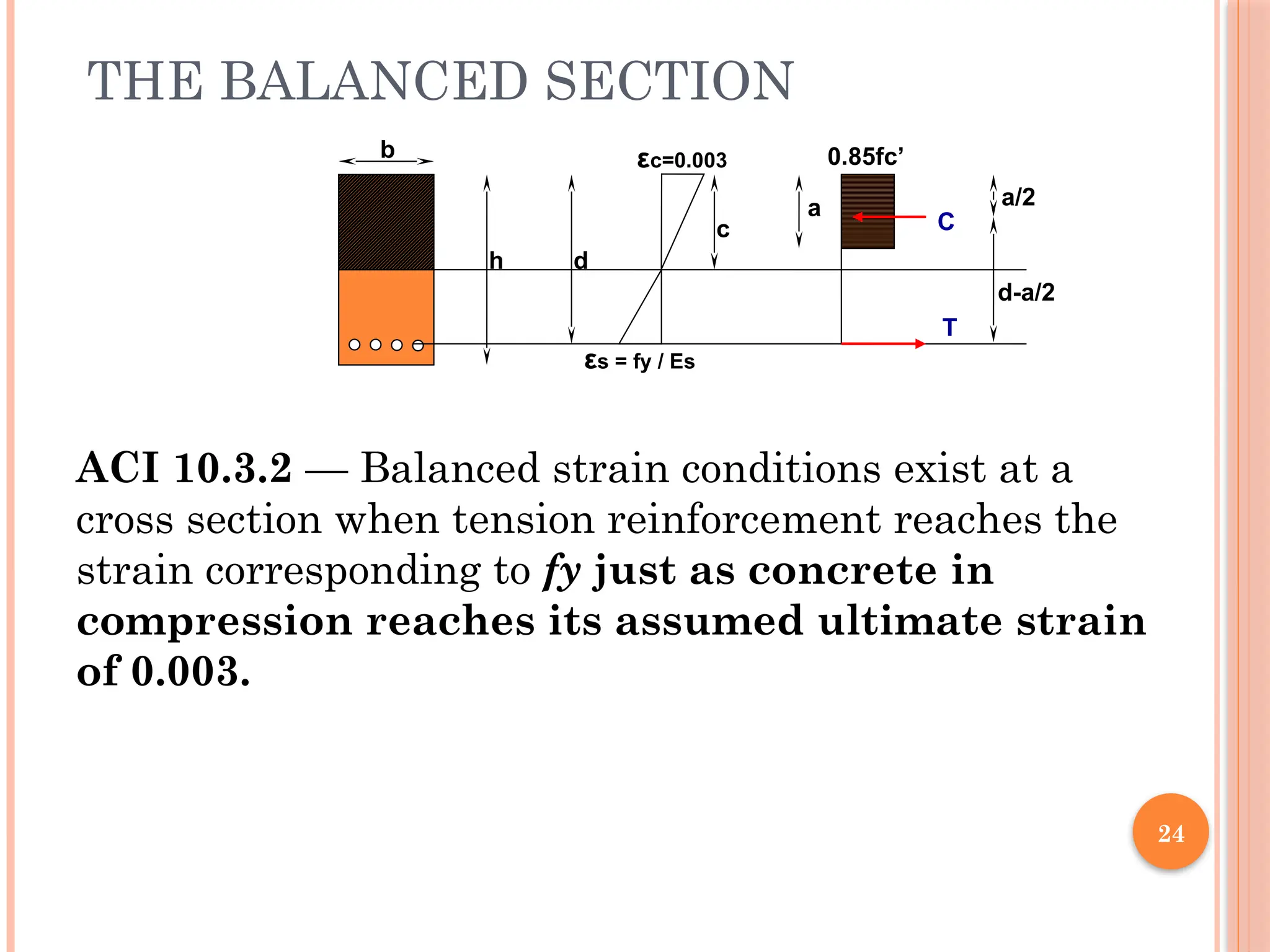
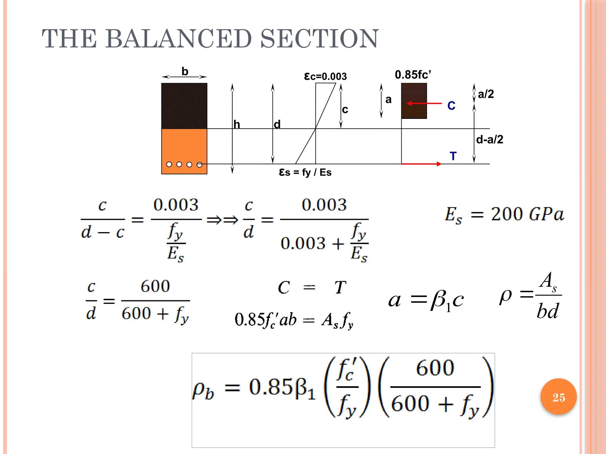
24
THE BALANCED SECTION
εc=0.003
εs= fy / Es
h d
c
0.85fc’
a a/2
d-a/2
b
C
T
ACI 10.3.2 — Balanced strain conditions exist at a
cross section when tension reinforcement reaches the
strain corresponding to fy just as concrete in
compression reaches its assumed ultimate strain
of 0.003.
28
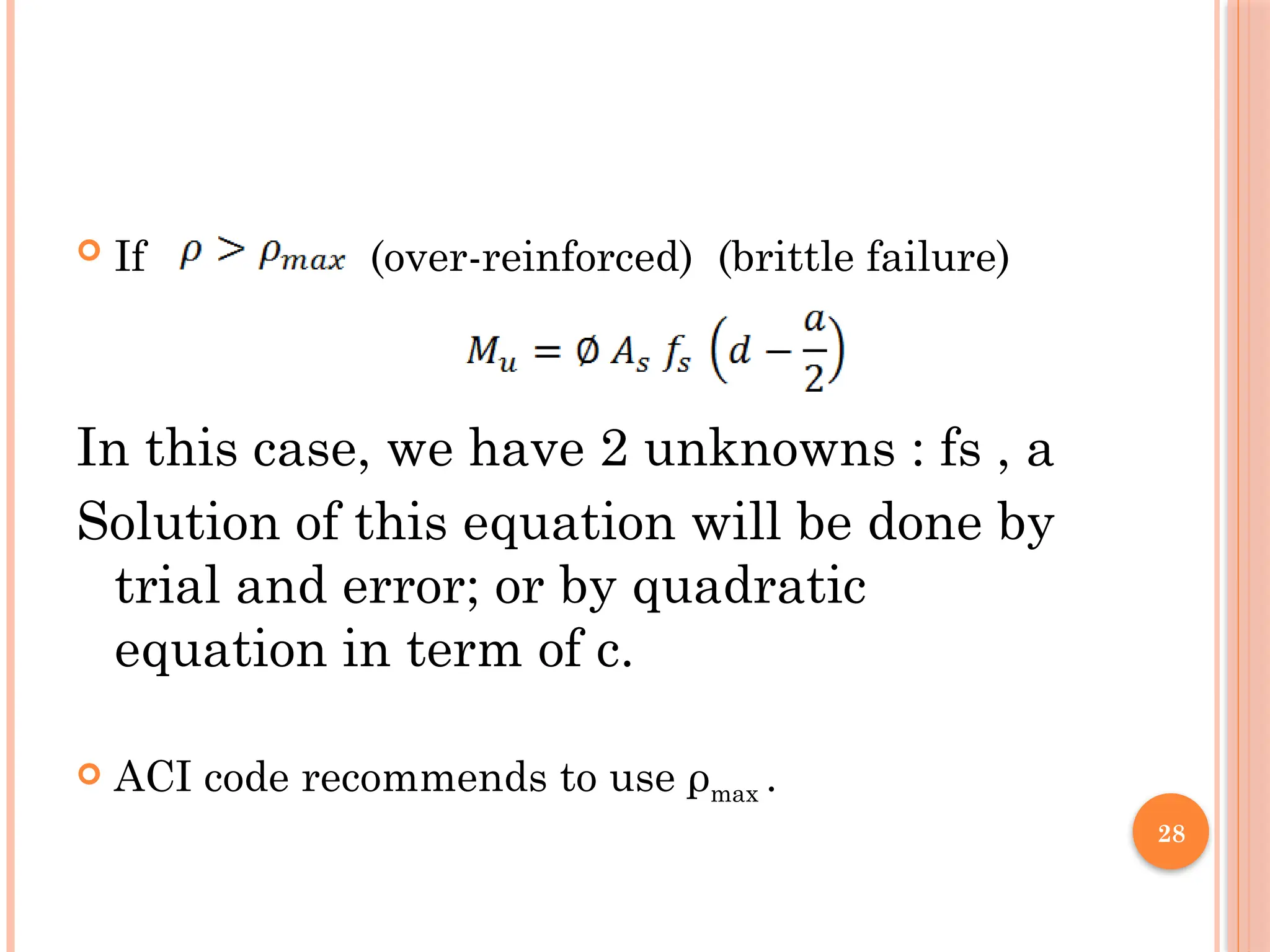
If (over-reinforced)(brittle failure)
In this case, we have 2 unknowns : fs , a
Solution of this equation will be done by
trial and error; or by quadratic
equation in term of c.
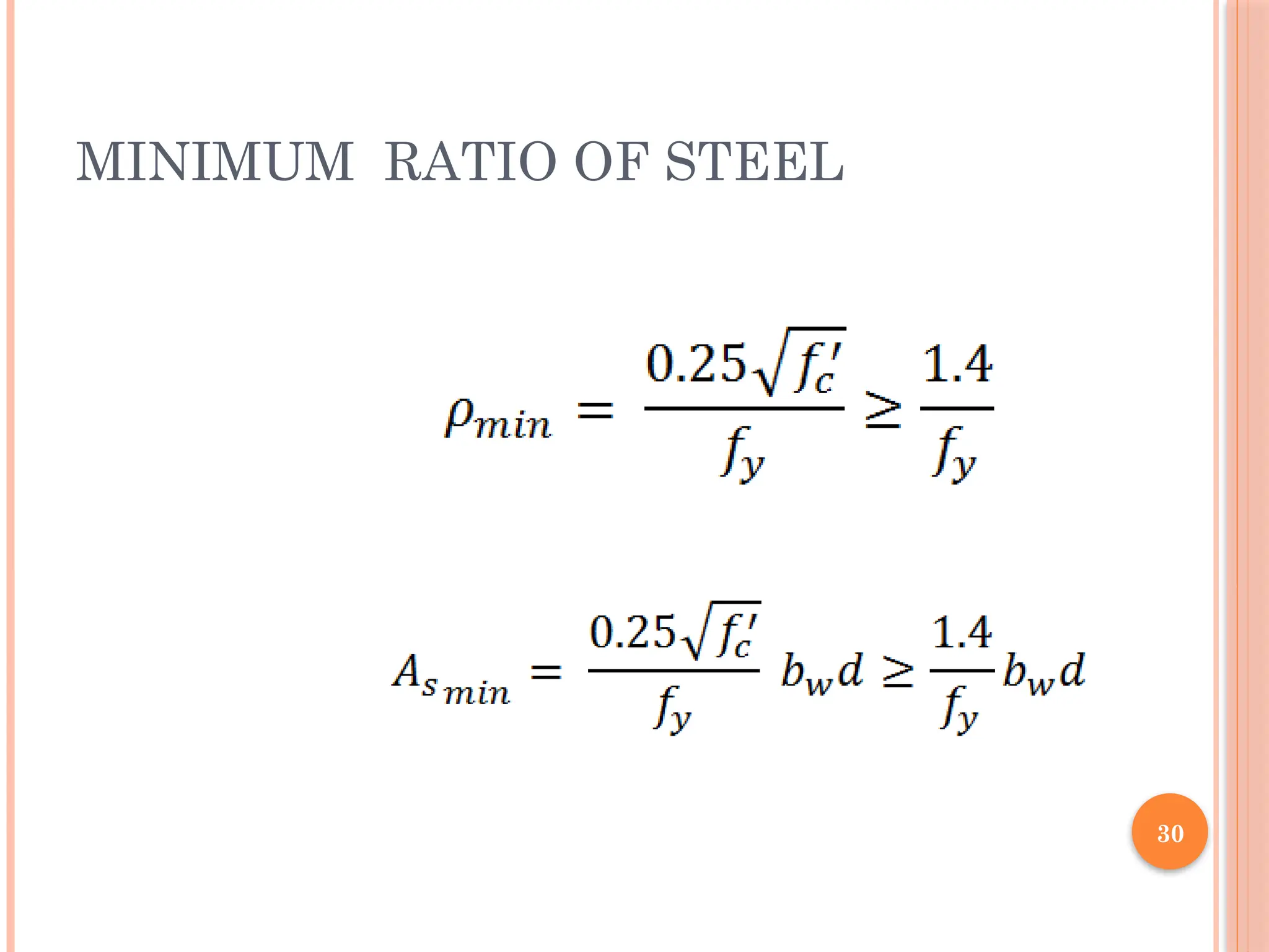
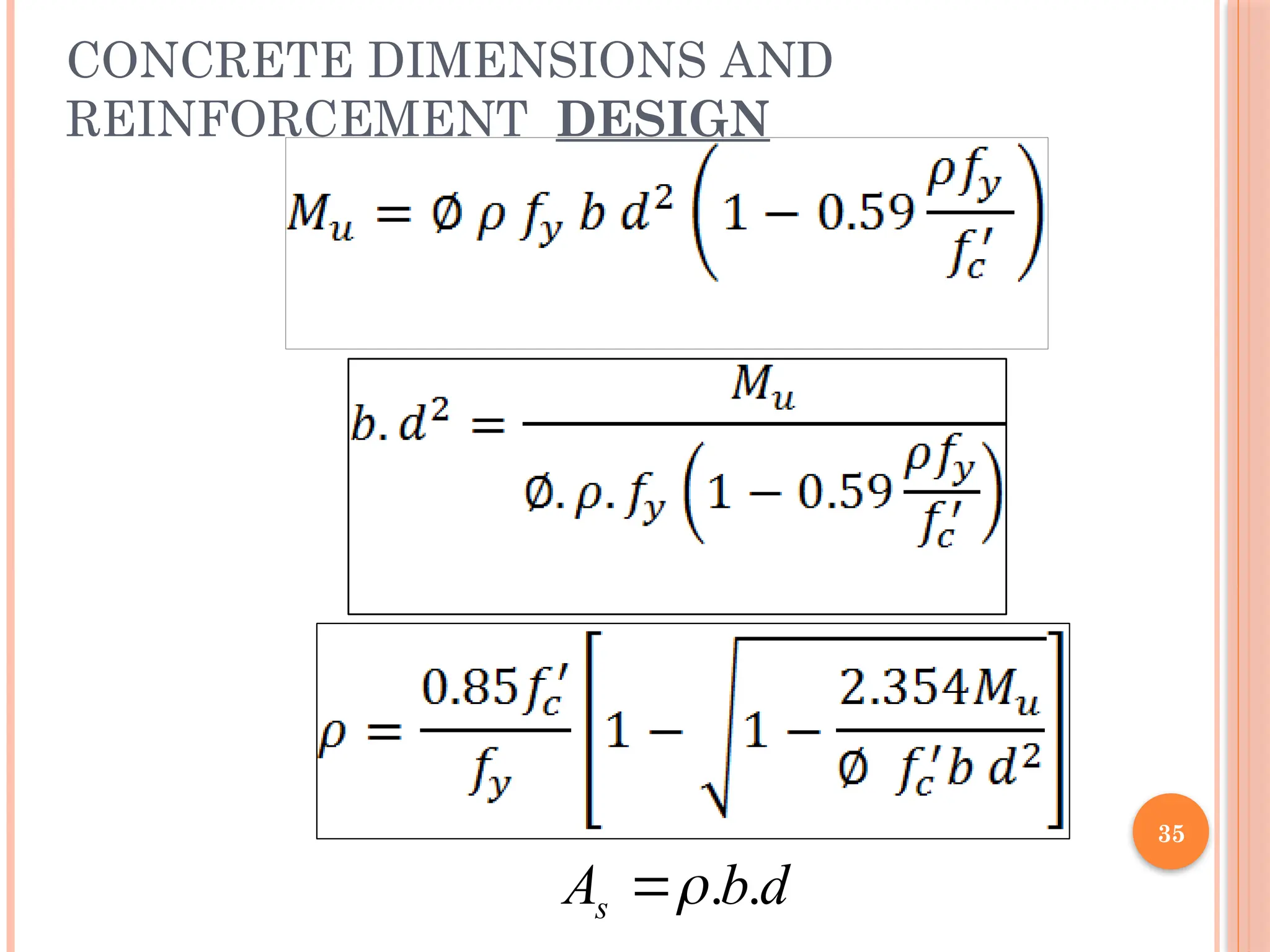
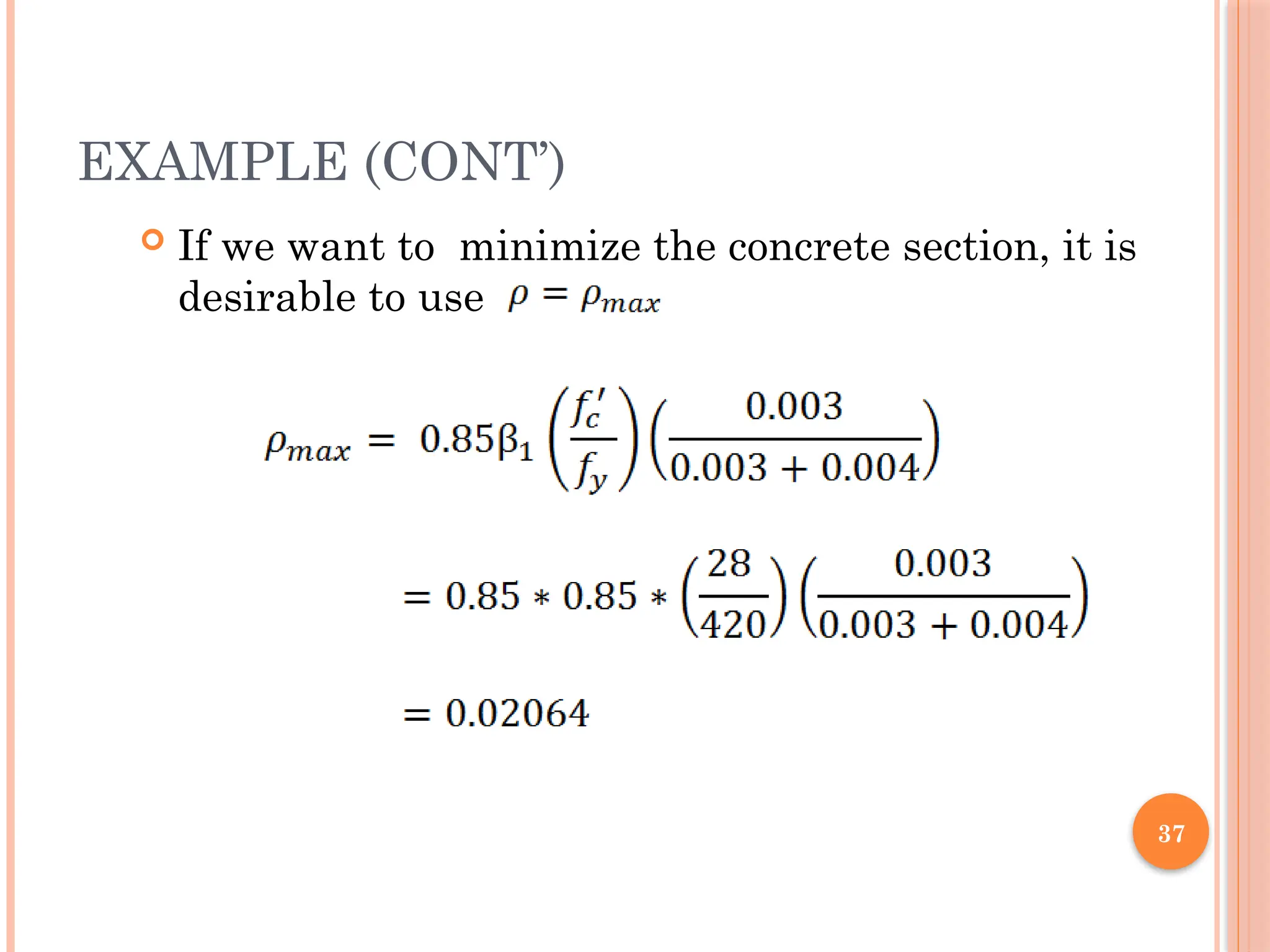
ACI code recommends to use ρmax .
31
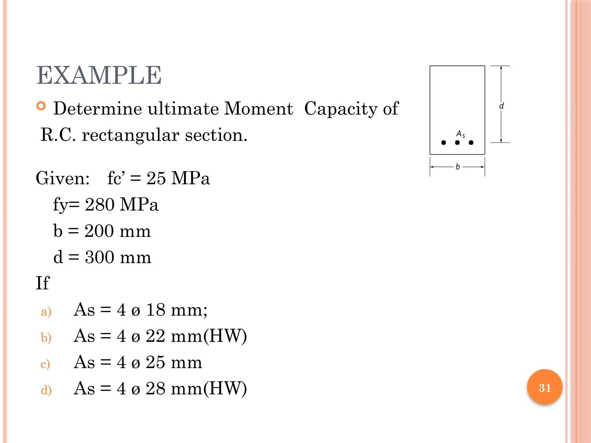
EXAMPLE
Determine ultimateMoment Capacity of
R.C. rectangular section.
Given: fc’ = 25 MPa
fy= 280 MPa
b = 200 mm
d = 300 mm
If
a) As = 4 ø 18 mm;
b) As = 4 ø 22 mm(HW)
c) As = 4 ø 25 mm
d) As = 4 ø 28 mm(HW)
36
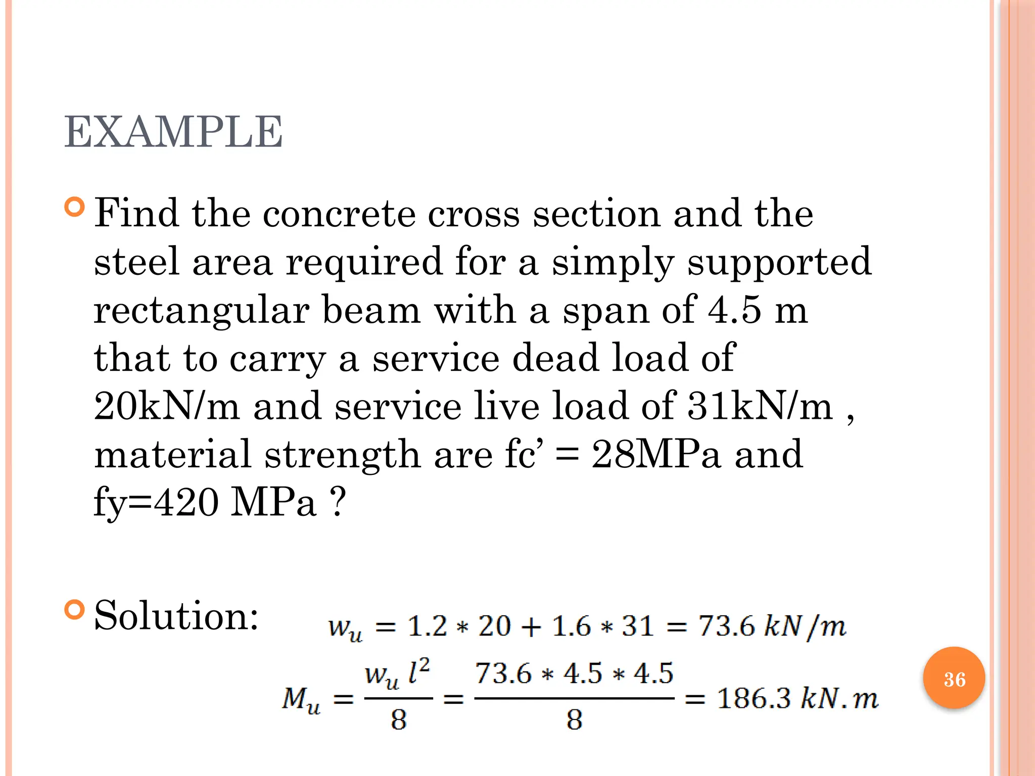
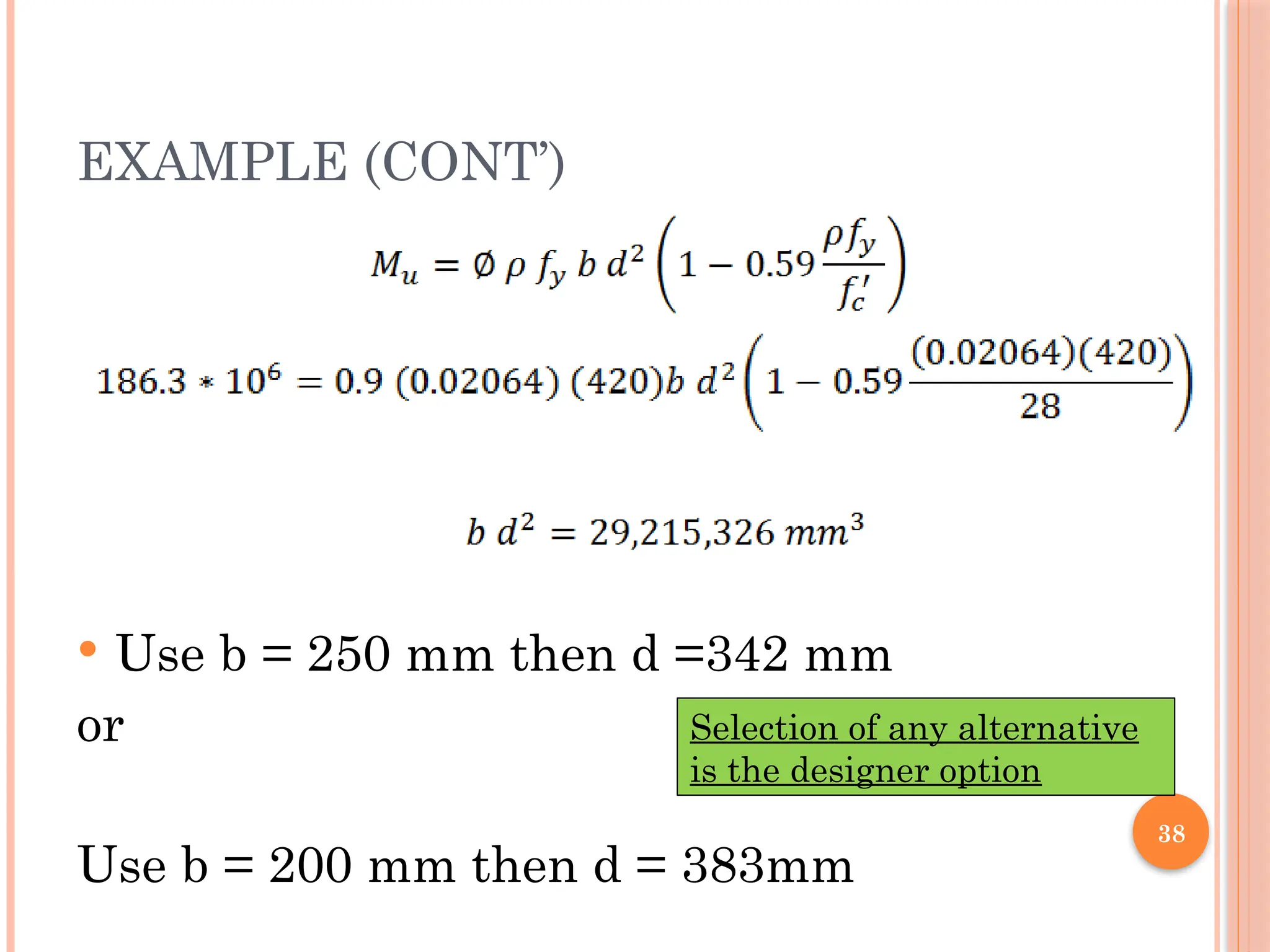
EXAMPLE
Find theconcrete cross section and the
steel area required for a simply supported
rectangular beam with a span of 4.5 m
that to carry a service dead load of
20kN/m and service live load of 31kN/m ,
material strength are fc’ = 28MPa and
fy=420 MPa ?
Solution:
38
EXAMPLE (CONT’)
Useb = 250 mm then d =342 mm
or
Use b = 200 mm then d = 383mm
Selection of any alternative
is the designer option
39.
39
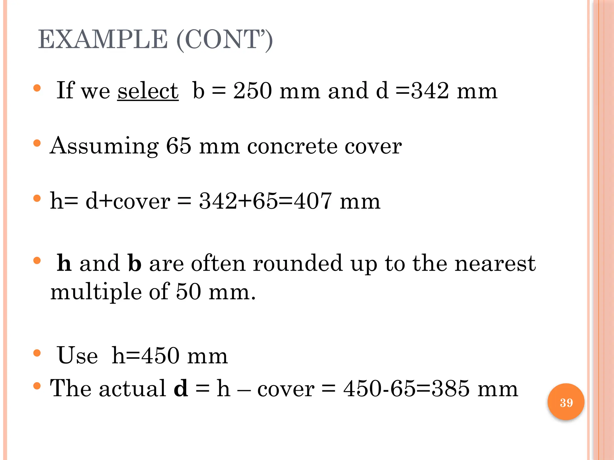
EXAMPLE (CONT’)
Ifwe select b = 250 mm and d =342 mm
Assuming 65 mm concrete cover
h= d+cover = 342+65=407 mm
h and b are often rounded up to the nearest
multiple of 50 mm.
Use h=450 mm
The actual d = h – cover = 450-65=385 mm
40.
40
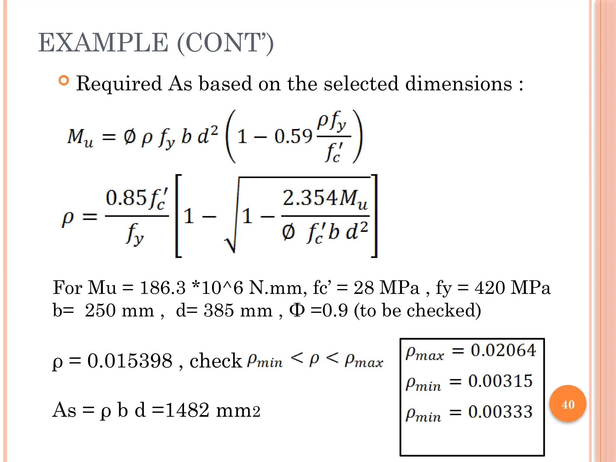
EXAMPLE (CONT’)
RequiredAs based on the selected dimensions :
For Mu = 186.3 *10^6 N.mm, fc’ = 28 MPa , fy = 420 MPa
b= 250 mm , d= 385 mm , Ф =0.9 (to be checked)
ρ = 0.015398 , check
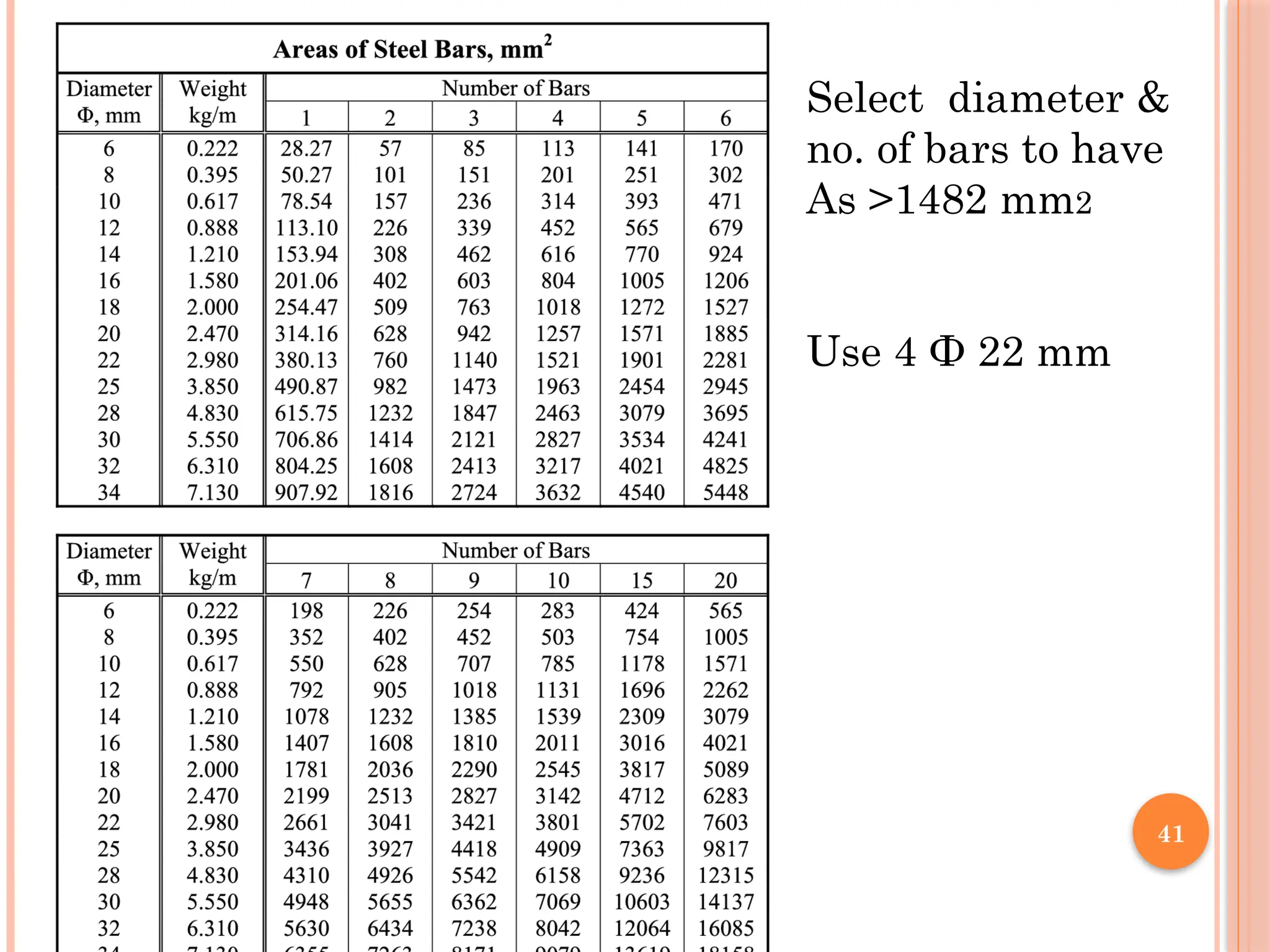
As = ρ b d =1482 mm2
42
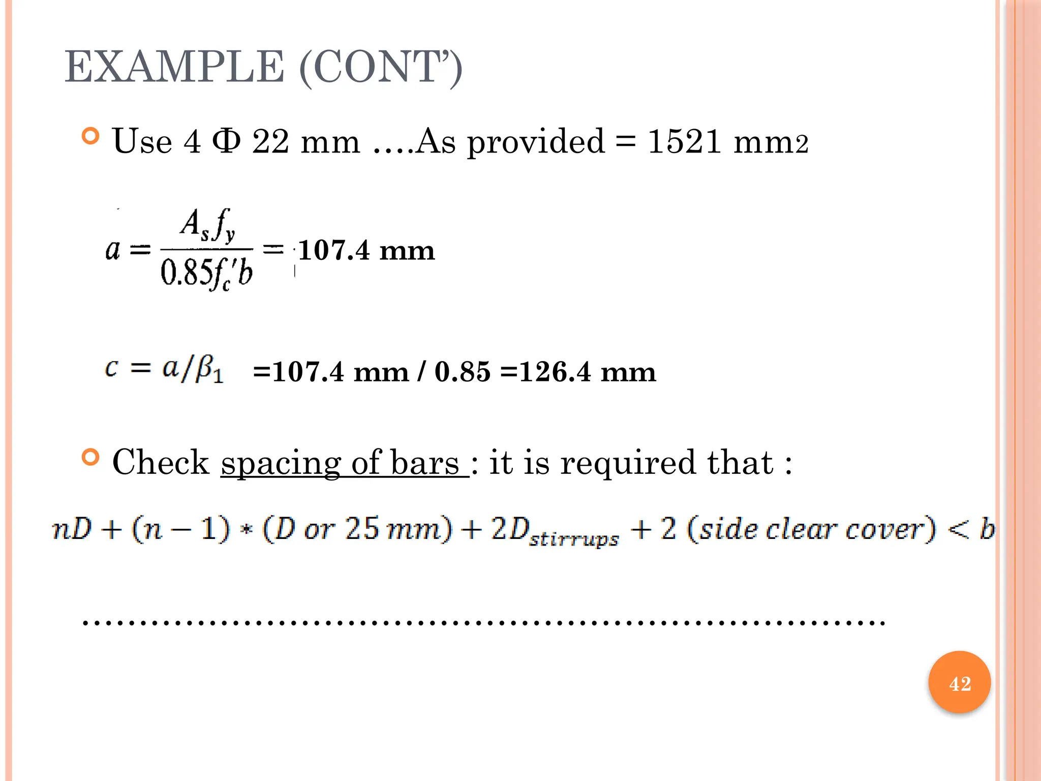
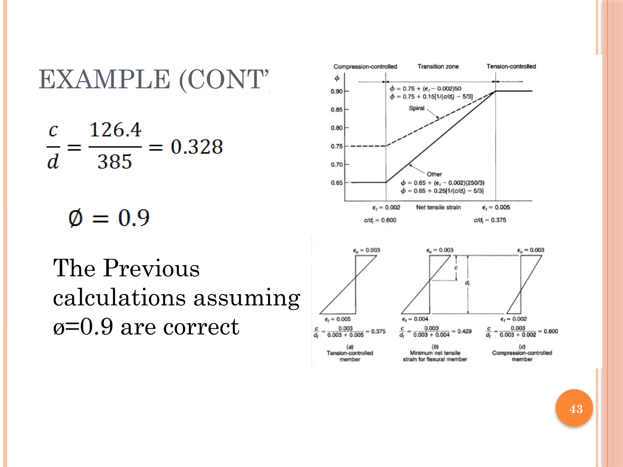
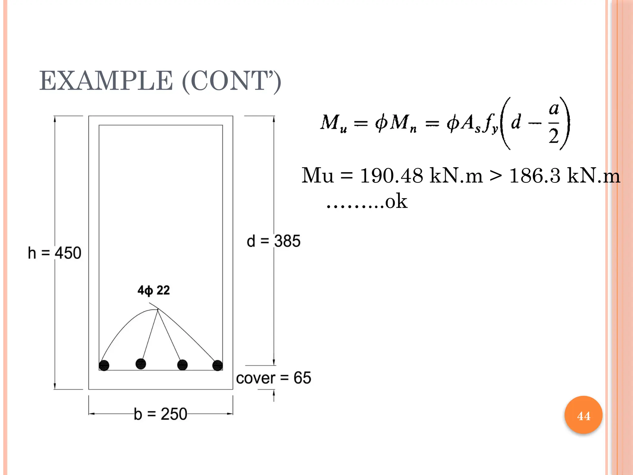
EXAMPLE (CONT’)
Use4 Ф 22 mm ….As provided = 1521 mm2
Check spacing of bars : it is required that :
…………………………………………………………….
107.4 mm
=107.4 mm / 0.85 =126.4 mm
45
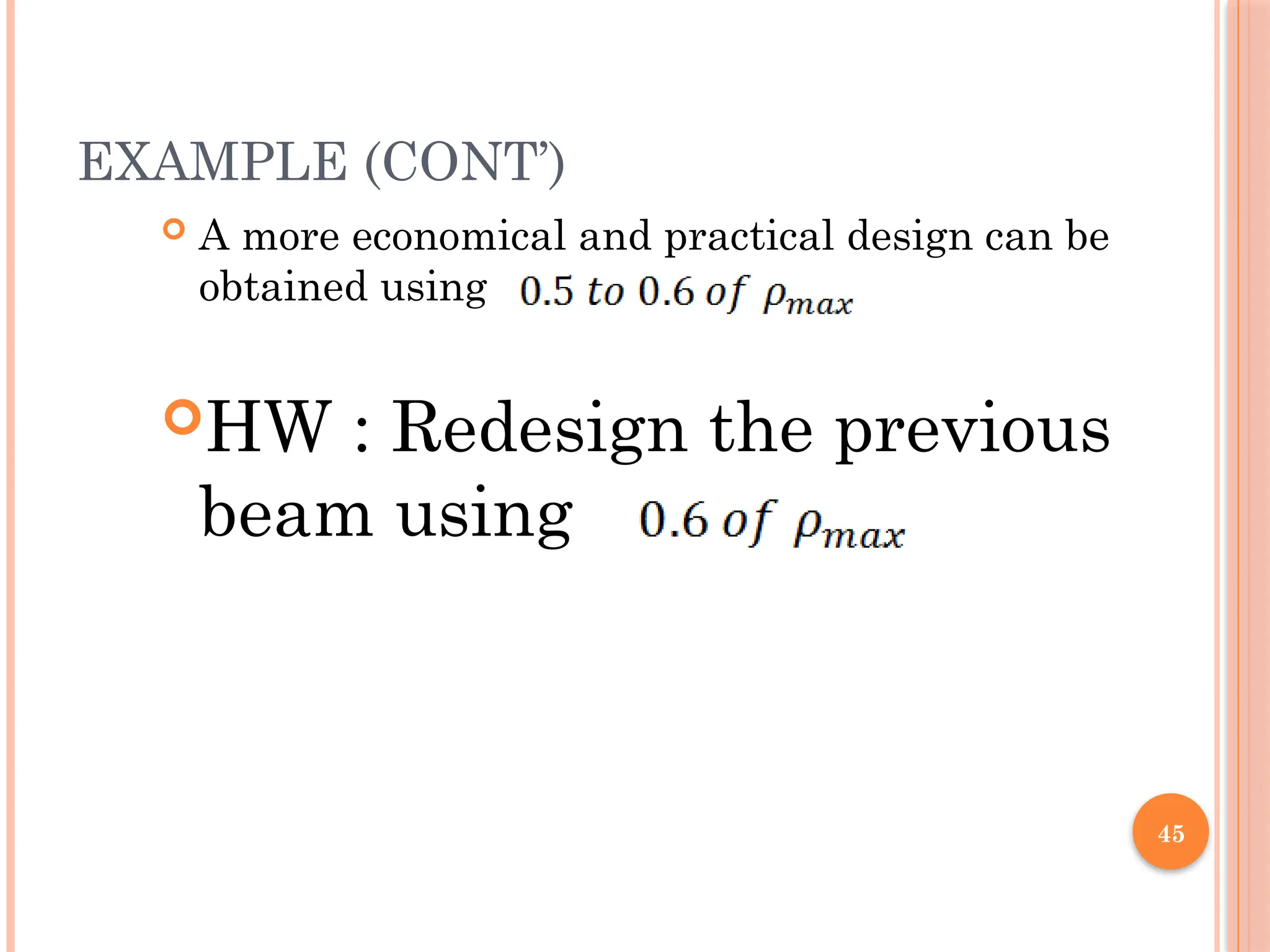
EXAMPLE (CONT’)
Amore economical and practical design can be
obtained using
HW : Redesign the previous
beam using
46.
46
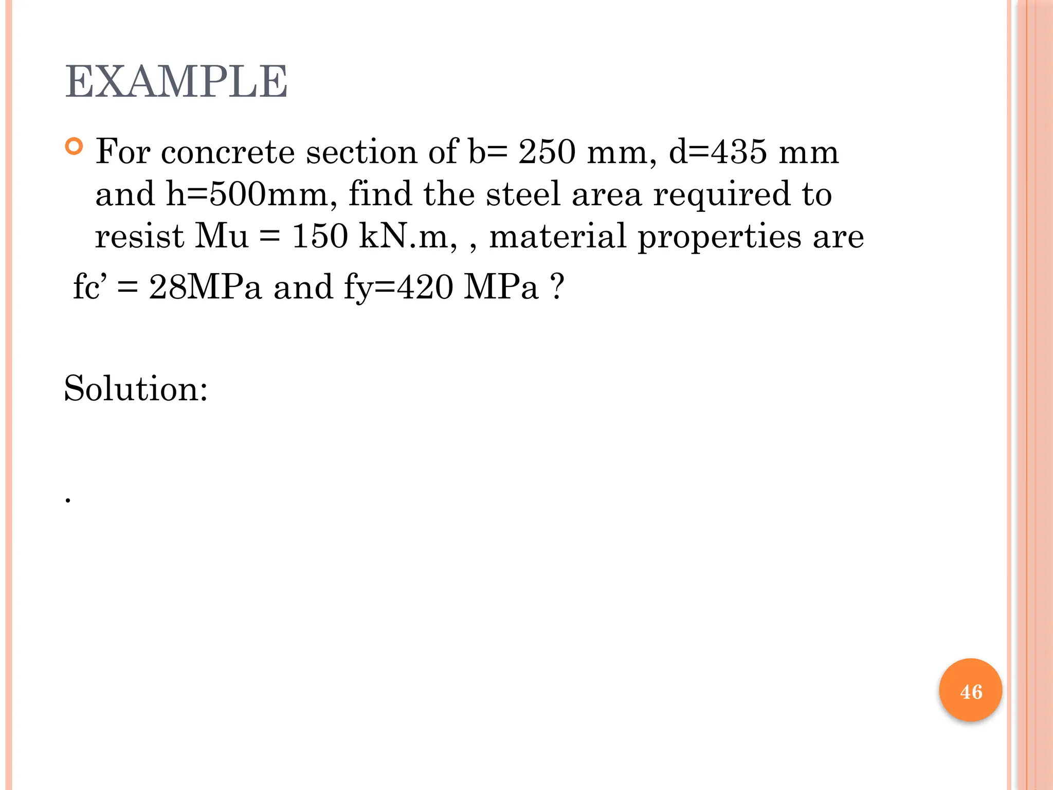
EXAMPLE
For concretesection of b= 250 mm, d=435 mm
and h=500mm, find the steel area required to
resist Mu = 150 kN.m, , material properties are
fc’ = 28MPa and fy=420 MPa ?
Solution:
.
47.
47
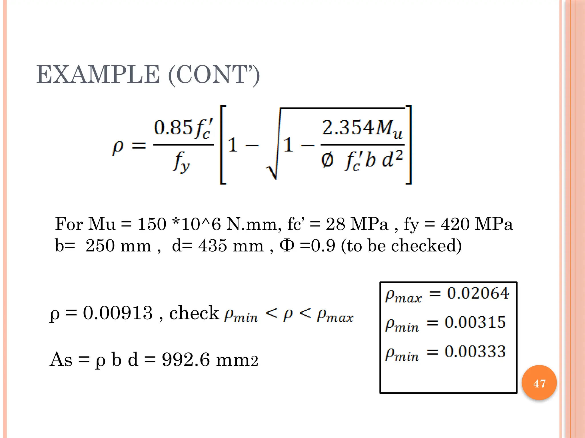
EXAMPLE (CONT’)
ρ =0.00913 , check
As = ρ b d = 992.6 mm2
For Mu = 150 *10^6 N.mm, fc’ = 28 MPa , fy = 420 MPa
b= 250 mm , d= 435 mm , Ф =0.9 (to be checked)
48.
48
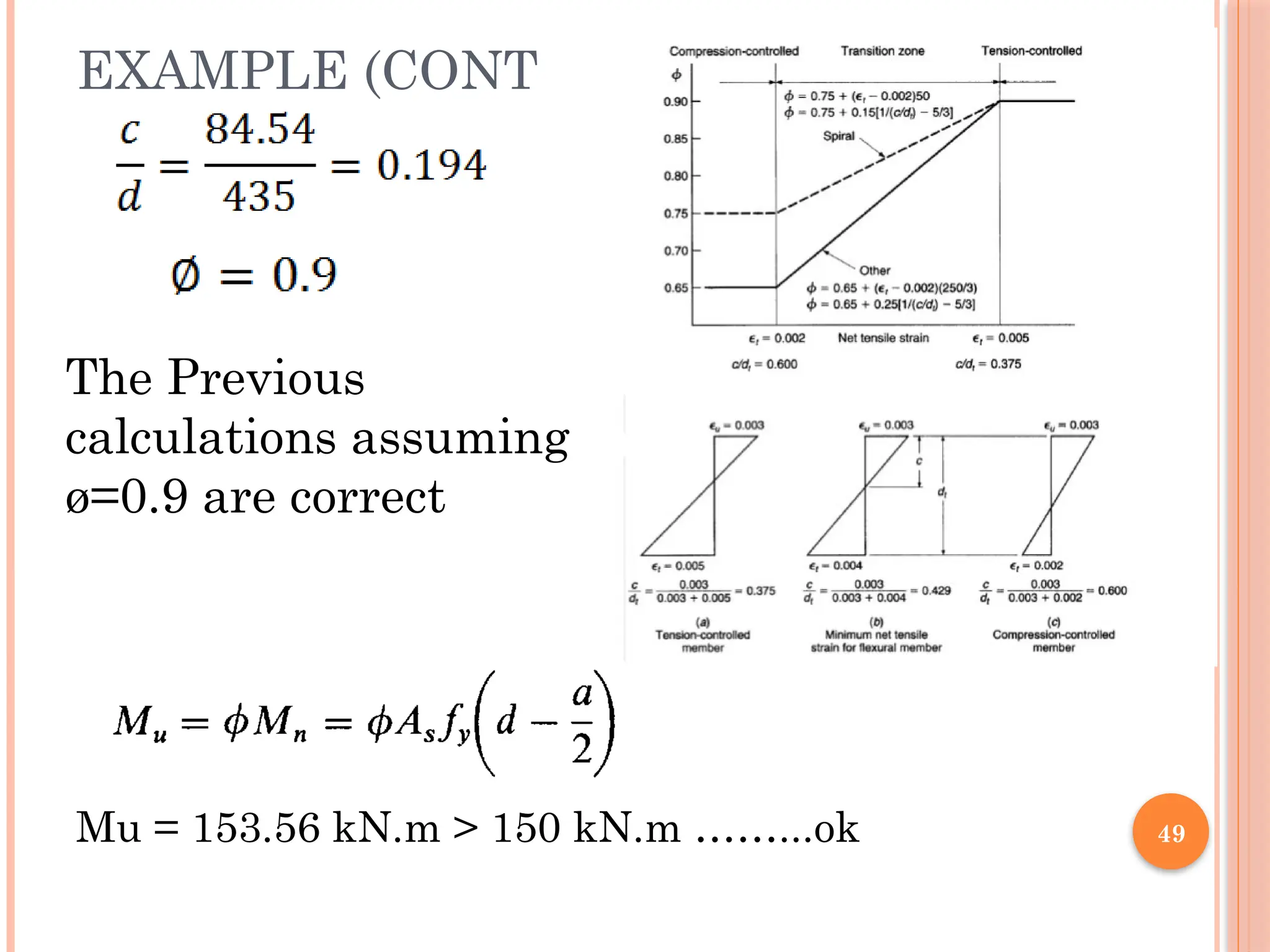
EXAMPLE (CONT’)
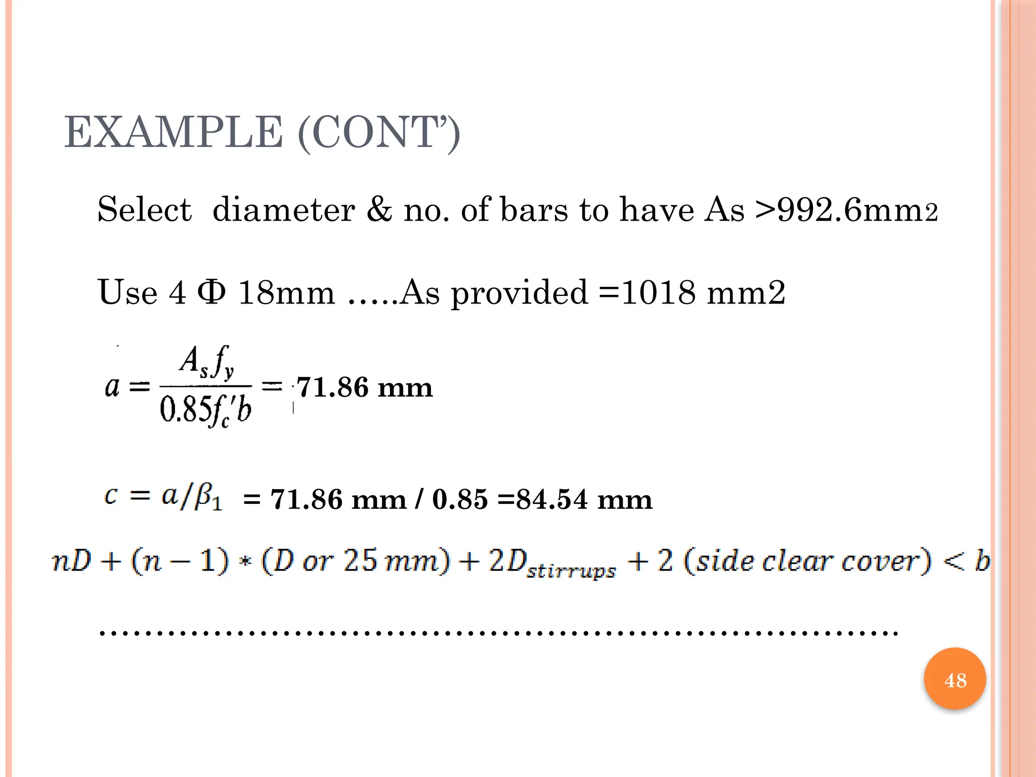
Select diameter& no. of bars to have As >992.6mm2
Use 4 Ф 18mm …..As provided =1018 mm2
…………………………………………………………….
71.86 mm
= 71.86 mm / 0.85 =84.54 mm
51
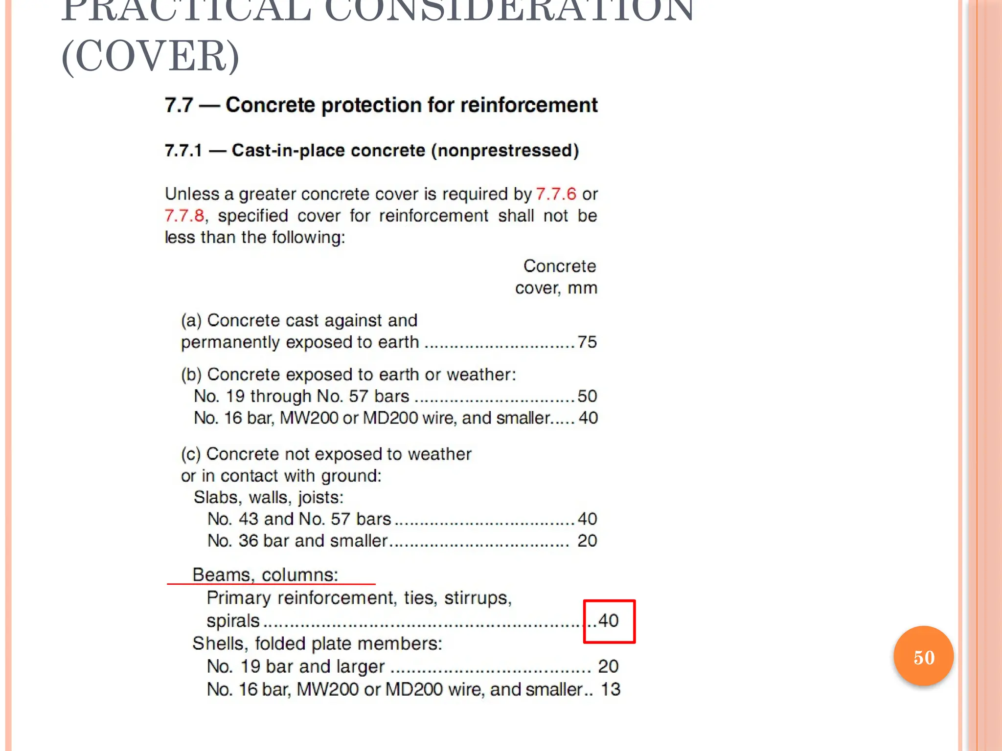
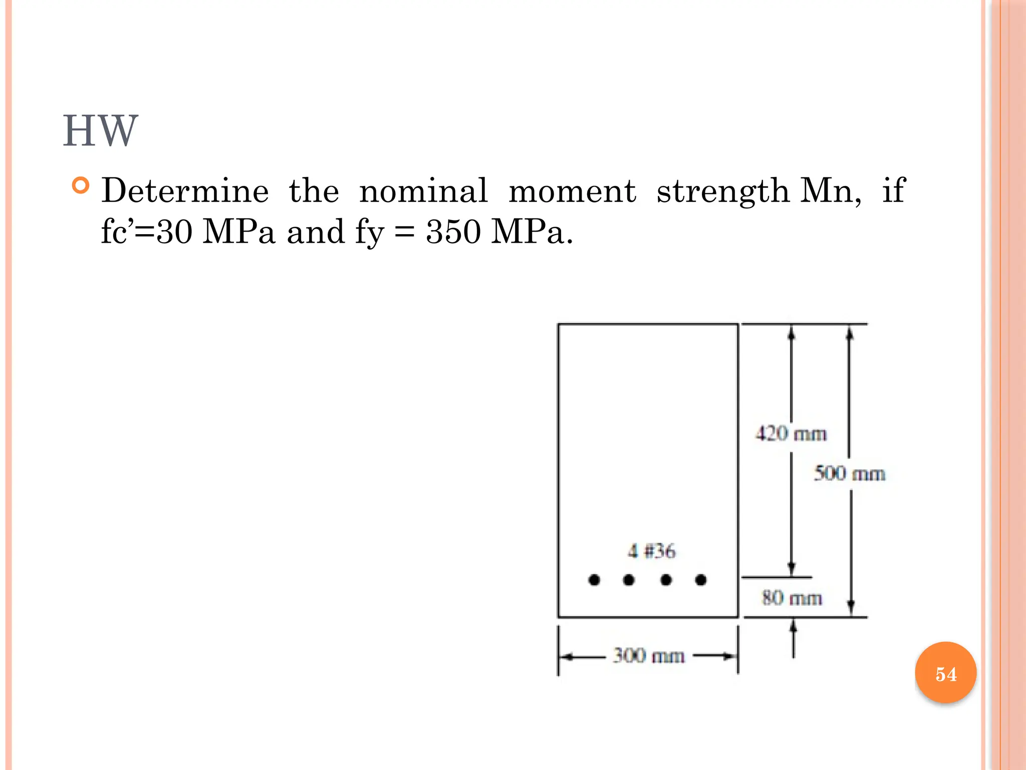
PRACTICAL CONSIDERATION
(DIMENSIONING)
hand b are almost rounded up to the nearest
multiple of 25 mm, and often to the next multiple
of 50 mm.
b and d are economically and practically chosen
with
d = (2 to 3)*b.