Download to read offline


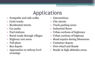
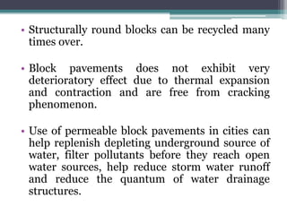
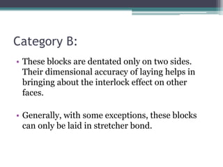
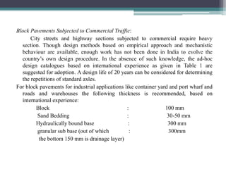
![Calculation of Stresses
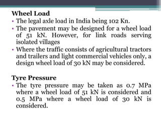
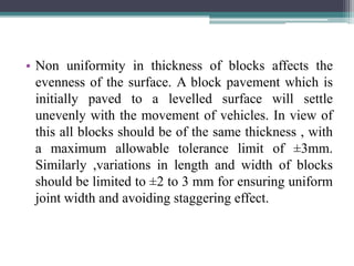
Edge Stresses:
(a) Due to load: The load stress in the critical edge region may be
obtained as per Westergaard analysis as modified by Teller and
Sutherland from the following correlation (metric units):
P I σle = 0.529 —(l+0.54fi)(41og 10 +log ]0 b-0.4048) ... ... (3)
where, σ le = load stress in the edge region, MPa
P = design wheel load, N
h = pavement slab thickness, mm
µ = Poisson's ratio for concrete
E = Modulus of elasticity for concrete, MPa
k = Modulus of subgrade reaction of the pavement foundation](https://image.slidesharecdn.com/pptrccroaddesign-201202164829/85/Ppt-rcc-road-design-13-320.jpg)
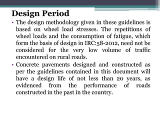
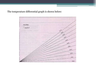
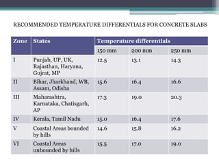
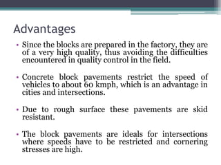
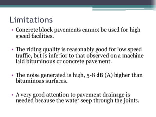
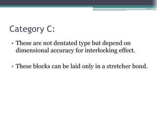
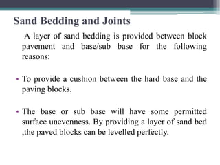
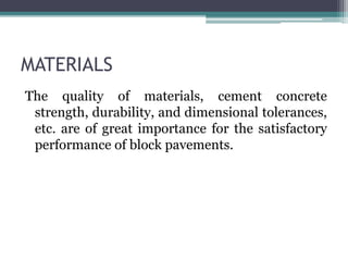
![Temperature differential: Temperature differential between the top
and bottom of concrete pavements causes the concrete slab to warp,
giving rise to stresses. The temperature differential is a function of solar
radiation received by the pavement surface at the location, losses due to
wind velocity, etc., and thermal diffusivity of concrete, and is thus
affected by geographical features of the pavement location. As far as
possible, values of actually anticipated temperature differentials at the
location of the pavement should be adopted for pavement design.
Corner stresses: The load stress in the corner region may be obtained
as per
Westergaard's analysis as modified by Kelley, from the following
correlation :
where,
Σlc = 3P/h^2[1-{a(2)^1/2/l}^1.2]
Σlc = load stress in the corner region, other notations remaining the
same as in the case of the edge stress formula.](https://image.slidesharecdn.com/pptrccroaddesign-201202164829/85/Ppt-rcc-road-design-15-320.jpg)


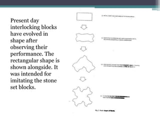
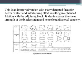
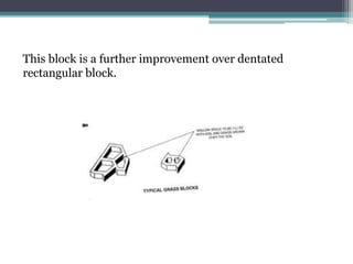
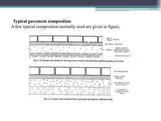
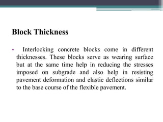


This document discusses cement concrete pavement and interlocking paving blocks for rural roads. It provides guidelines on designing cement concrete pavements, including recommendations for wheel load, subgrade characterization, sub-base provision, concrete strength, joint spacing, and an example design. It also outlines applications, advantages, and IRC specifications for interlocking concrete block pavements.


