The document contains homework assignments and solutions for the course 'Prestressed and Precast Concrete Structures' at Aalto University, focusing on various design and analysis tasks related to prestressed concrete elements. The assignments require students to apply European standards and involve calculations pertaining to beam design, reinforcement, and prestress losses. Each task is presented with detailed specifications, objectives, and required calculations for effective learning in structural engineering.

![Aalto University J. Hanka
Rak-43.3111 Prestressed and Precast Concrete Structures 2016 20.1.2016
Homework 1, Working stress design 1(1)
Return to MyCourses in PDF-format.
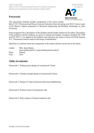
You are designing a post-tensioned single-span T-beam-slab that will be prestressed with unbonded monostrand
tendons. Slab is loaded with a permanent dead load gk=0,5 kN/m2
and liveload qk=5 kN/m2
. Concrete selfweight is
ρc=25kN/m3
. Slab is prestressed before imposed dead loads are installed. Slab (=T-beam flange) thickness is 200mm.
Beam supports can be assumed to be hinged.
Information:
- Concrete strength at final condition: C30/37 ; fck=30MPa ; fctm=2,89MPa ; Ecm=32,8GPa
- Concrete strength during stressing: C25/30 ; fck.i=25MPa ; fctm.i=2,56MPa ; Ecm.i=31GPa
- Exposure classes XC3, XD1. Design working life: 50 years.
- Unbonded tendons. Grade St1600/1860, fp0,1k=1600 MPa, fpu=1860MPa, Ep=195GPa
- Area of one tendon Ap1=150mm2
. Assumed jacking force of one tendon is Pmax=210kN.
- Assumed smallest distance of tendon centroid from the bottom/top of the section ep=90mm
- Initial prestress losses (friction, slipping and elastic) are assumed to be Δini=10% [Pm.0=Pmax(1-Δini)]
- Total prestress losses (initial & timedependant) are assumed to be Δf=15% [Pm.t=Pmax(1-Δf)]
- Beam span length: L=14,5m. Spacing of beams (slab span lengths) L2=8,3m.
- Liveload combination factors; ψ0=0,7; ψ1=0,5; ψ2=0,3 (EN 1990 Class G, garages)
- Quasi-permanent combination of actions: pqp=∑gj + ∑ψ2qi
- Frequent combination of actions: pf=∑gj + ψ1q1 + ∑ψ2,i+1qi+1
- Characteristic combination of actions: pc=∑gj + q1 + ∑ψ2,i+1qi+1
Goal of the assignment is to design a typical T-beam section (find the beam height, beam width, number of tendons
and tendon geometry at midspan) in such a way that design criteria’s given in table 1 are satisfied.
Figure 1. Post-tensioned T-beam section.
Table 1. Allowable stresses of concrete in serviceability limit state (SLS) for unbonded tendons.
Condition # Combination EN1990 Limitation EC2 Clause
Initial
I Max tension Initial σct.ini < fctm.i
II Max compression Initial σcc.ini < 0,6*fck.i 5.10.2.2(5)
Final
III Max tension Frequent σct.f < fctm
IV Max compression Characteristic σcc.c < 0,6*fck 7.2(2)
V Max compression Quasi-permanent σcc.qp < 0,45*fck 7.2(3)
Max deflection Quasi-permanent Δ < Span / 250 7.4.1(4)
a) Form the calculation model of the beam. Choose the beam height H and width Bw. Calculate the effect of actions
due to selfweight, dead load and live load at midspan.
b) Calculate the effective flange width (beff) according to EN 1992-1-1 chapter 5.3.2.1(2).
c) Calculate the cross section properties for the gross-cross section used in the prestress design:
- Moment of inertia and cross section area Igr, Agr
d) Choose the amount of tendons and tendon geometry at midspan (distance of tendon centroid from bottom of
beam). Calculate the axial force and bending moment due to prestress at midspan.
e) Check that the allowable stresses given in table 1 are not exceeded in critical section at midspan.
f) Draw a schematic drawing (cross section) of the tendon geometry.
Tip for (c), (d):
http://www.adaptsoft.com/resources/ADAPT_T901_Effective-Width-PT-beamsr.pdf
200
Bw
H](https://image.slidesharecdn.com/rak-43-160416142135/85/Prestressed-concrete-Course-assignments-2016-2-320.jpg)
![Aalto University J. Hanka
Rak-43.3111 Prestressed and Precast Concrete Structures 2016 5.2.2016
Homework 2, Ultimate strength design of T-beam 1(1)
Return to MyCourses in PDF-format.
You are designing a post-tensioned single-span T-beam-slab that will be prestressed with unbonded tendons. Slab is
loaded with a permanent dead load gk=0,5 kN/m2
(surface structures) and liveload qk=5 kN/m2
. Concrete selfweight is
ρc=25kN/m3
. Beam supports can be assumed to be hinged. Width of the supports at beam ends is a0=400mm.
Information:
- Concrete strength: C30/37; fck=30MPa; fctm=2,89MPa; Ecm=32,8GPa ; εcu=0,35% ; λ=0,8 ; η=1,0
- Exposure classes XC3, XD1. Design working life: 50 years.
- Unbonded tendons. Grade St1600/1860, fp0,1k=1600 MPa, fpu=1860MPa, Ep=195GPa
- Reinforcement steel Es=200GPa, fyk=500 MPa
- Area of one tendon Ap1=150mm2
. Total number of tendons is 14. Assumed jacking force of one tendon is
Pmax=210kN. Distance between bottom of the beam and centroid of the tendons at midspan is
eP(x=L/2)=90mm and at beam ends is ep(x=0)=ep(x=L)=700mm
- Initial prestress losses (friction, slipping and elastic) are assumed to be Δini=10% [Pm.0=Pmax(1-Δini)]
- Total prestress losses (initial & timedependant) are assumed to be Δf=15% [Pm.t=Pmax(1-Δf)]
- Beam span length: L=14,5m. Spacing of beams (slab span lengths) L2=8,3m.
- Liveload combination factors; ψ0=0,7; ψ1=0,5; ψ2=0,3 (EN 1990 Class G, garages)
- Partial factors for loads in ULS: γG=1,35 ; ξγG=1,15 ; γQ=1,5 ; KFI=1
- Partial factors for tendon force in ULS: γP.fav= γP.unfav=1,0
- ULS combination of actions: pEd=∑ ξγG gj + γQ q1 + ∑ γQ ψ0,i+1qi+1
- Assumed stress increase of unbonded tendons in ultimate limit state Δσp.ULS=50MPa [EN1992-1-1 5.10.8(2)]
- Partial factors for materials γc=1,5; αcc=0,85 ja γs=γp=1,15 [EN 1992-1-1 2.4.2.4(1)]
- Concrete cover to the shear reinforcement is c=35mm.
Goal of the assignment is to calculate the required amount of bending and shear reinforcement.
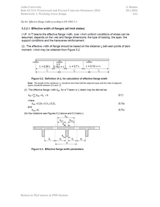
Figure 1. Post-tensioned T-beam section and sideview with the tendon geometry.
a) Form the calculation model of the beam. Calculate the design value of line load pEd in ULS for the beam.
b) Calculate the design value of effect of actions due bending moment MEd.
c) Calculate the required amount of reinforcement As.req for the bending moment MEd obtained in (a). Effective width
of the flange may be assumed to be beff=5600mm.
d) Calculate the design value of effects of actions due to shear force VEd at critical section.
e) Calculate the required amount of shear reinforcement Asw.req for the shear force VEd obtained in (a).
f) Choose the actual amount of bending & shear reinforcement and place them to the cross section. Sketch a drawing
of the cross section with the reinforcement.
=200
=700
=900](https://image.slidesharecdn.com/rak-43-160416142135/85/Prestressed-concrete-Course-assignments-2016-4-320.jpg)
![Aalto University J. Hanka
Rak-43.3111 Prestressed and Precast Concrete Structures 2016 5.2.2016
Homework 2, Ultimate strength design of T-beam 1(1)
Return to MyCourses in PDF-format.
(a) (b) (c)
Figure 2. (a) Calculation model in ultimate limit state. (b) Stress-strain curve of prestressing steel [EC2 fig 3.10].
(c) Stress-strain curve of reinforcing steel [EC2 fig 3.8].
Tip (c): Calculation model bending moment resistance in ULS for unbonded tendons:](https://image.slidesharecdn.com/rak-43-160416142135/85/Prestressed-concrete-Course-assignments-2016-5-320.jpg)
![Aalto University J. Hanka
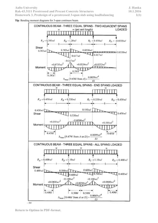
Rak-43.3111 Prestressed and Precast Concrete Structures 10.1.2016
Homework 3, Predesign of a prestressed 3-span slab using loadbalancing 1(1)
Return to Optima in PDF-format.
3-span continuous slab of parking garage in figure 1 will be prestressed with unbonded tendons. Slab is loaded with a
dead load gk=0,5kN/m2
and liveload qk=5kN/m2
. Concrete selfweight is ρc=25kN/m3
. Slab is prestressed before surface
structures are installed. Live load may vary span by span.
Information:
- Concrete strength at final condition: C30/37 ; fck=30MPa ; fctm=2,89MPa ; Ecm=32,8GPa
- Concrete strength during stressing: C25/30 ; fck.i=25MPa ; fctm.i=2,56MPa ; Ecm.i=31GPa
- Exposure classes XC3, XD1. Design working life: 50 years.
- Unbonded tendons. Grade St1600/1860, fp0,1k=1600 MPa, fpu=1860MPa, Ep=195GPa
- Area of one tendon Ap1=150mm2
. Assumed jacking force of one tendon is Pmax.1=210kN.
- Assumed smallest distance of tendon centroid from the bottom/top of the section ep=50mm
- Initial prestress losses (friction,slipping and elastic) are assumed to be in all spans Δini=10% [Pm.0=Pmax(1-Δini)]
- Total prestress losses (initial & timedependant) are assumed to be in all spans Δf=15% [Pm.t=Pmax(1-Δf)]
- Slab span lengths L=8,3m. 2nd
degree parabolic tendon geometry: u(x)=ax2
+bx+c
- Liveload combination factors; ψ0=0,7; ψ1=0,5; ψ2=0,3 (EN 1990 Class G, garages)
- Quasi-permanent combination of actions: pqp=∑gj + ∑ψiqi
- Frequent combination of actions: pf=∑gj + ψ1q1 + ∑ψ2,i+1qi+1
- Characteristic combination of actions: pc=∑gj + q1 + ∑ψ2,i+1qi+1
- Allowable deflection for quasi-permanent combination: L/250
Goal of the assignment is to find the thickness of the slab (h), spacing of tendons (ccp) / number of tendons per unit
width (np) and tendon geometry (eA, eB, eC).
Figure 1. Three-span post-tensioned slab with hinged supports.
Design in SLS using theory of elasticity:
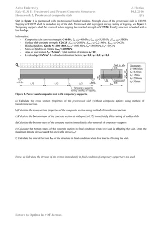
a) Choose thickness of the slab (h) and load to be balanced (pbal), so that the maximum value of deflection Δqp due to
quasi-permanent combination of actions does not exceed the allowable value for deflection (L/250). Coefficient of
creep for concrete may be assumed to be φ=2.
b) Choose the tendon geometry (eA, eB, eC) and required spacing of tendons (ccp) in such a way that the balancing load
chosen in (a) is reached.
c) Check that the allowable stresses (σct.max<fctm.i ; σc.max<0,6fck.i) are not exceeded in critical section when slab is
loaded with initial tendon force Pm.0 (initial situation during prestressing).
d) Check that the allowable stresses (σct.max<fctm ; σc.max<0,45fck) are not exceeded in critical section when slab is
loaded with final tendon force Pm.t and frequent combination combination of actions pf.
e) Draw a schematic drawing (sideview and cross section) of the tendon geometry.
EXTRA) How would the design differentiate if bonded tendons were used instead of unbonded tendons.
Instructions: You can make justified assumptions and simplifications in the calculations. It is not required to round the
tendon geometry on top of the support. Use gross-cross section properties in the calculations.](https://image.slidesharecdn.com/rak-43-160416142135/85/Prestressed-concrete-Course-assignments-2016-6-320.jpg)
![Aalto University J. Hanka
Rak-43.3111 Prestressed and Precast Concrete Structures 10.1.2016
Homework 4, Prestress losses of a continuous slab 1(1)
Return to Optima in PDF-format.
Slab and tendon
Geometry:
L=8.3m ; a0=0,5m
h=200mm
L1=0,4L ; L0=L/10
eA=eB=eC=h/2-ep
1=Active end
2=Anchorage end
3-span continuous slab of parking garage in figure 1 will be prestressed with unbonded tendons. Slab is loaded with a
dead load gk=0,5kN/m2
(surface structures) and liveload qk=5kN/m2
. Slab is prestressed before surface structures are
installed. Live load may vary span by span.
Information:
- Concrete strength at final condition: C30/37 ; fck=30MPa ; fctm=2,89MPa ; Ecm=32,8GPa
- Concrete strength during stressing: C25/30 ; fck.i=25MPa ; fctm.i=2,56MPa ; Ecm.i=31GPa
- Unbonded tendons. Grade St1600/1860, fp0,1k=1600 MPa, fpu=1860MPa, Ep=195GPa
- Initial stress (force of jack/area of tendons) σmax=1400 MPa. Pmax=210kN / Tendon
- Area of one tendon Ap1=150mm2
. Spacing of tendons ccp=400mm
- Smallest distance of tendon centroid from the bottom/top of the section ep=50mm
- 2nd
degree parabolic tendon geometry: u(x)=ax2
+bx+c
Goal of the assignment is to calculate the immediate losses due to friction, deformation and anchorage set.
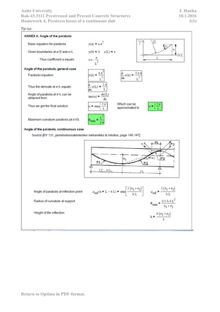
Figure 1. Three-span unbonded post-tensioned slab with hinged supports.
a) Calculate the immediate losses due to friction ΔPμ and instantaneous deformation of
concrete ΔPel span by span. How much of the initial jacking stress is lost at the anchorage
end?
b) Calculate the immediate losses due to anchorage set ΔPsl.
c) Draw a curve that describes the tendon force after initial losses from jacking end (x=0) to
the dead anchorage end (x=3L).
d) How much of the initial maximum prestress is lost span-by-span?
e) What methods could be used to compensate prestress losses?
f) Calculate the theoretical elongation of the tendons at the active end after stressing.
Tip (a): Immediate prestress losses due to friction can be calculated with the following information
* Losses due to friction in post-tensioned tendons: ΔPμ(x)=P0(1-e-μ(θ+kx)
) [EC2 Eq.(5.45)]
* θ is the sum of the angular displacements over a distance x
* coefficient of friction between the tendon and its duct μ=0,05
* unintentional angular displacement for internal tendons (per unit length) k = 0,020 m-1
* slip of tendon δ= 5 mm
Tip (b): Losses due to anchorage set and elastic shortening is treated in the course textbook [Naaman] chapters 8.17 and
8.7 respectively.
Tip (d): http://www.kontek.ee/public/files/Post-tensioning%20MeKano4,%20S.A..pdf page 25
Instructions: You can make justified assumptions and simplifications in the calculations. Use gross-cross section
properties in the calculations.
1
2](https://image.slidesharecdn.com/rak-43-160416142135/85/Prestressed-concrete-Course-assignments-2016-8-320.jpg)