Downloaded 219 times

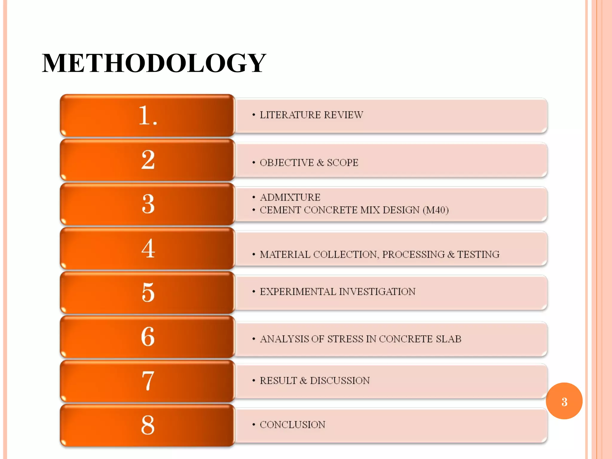
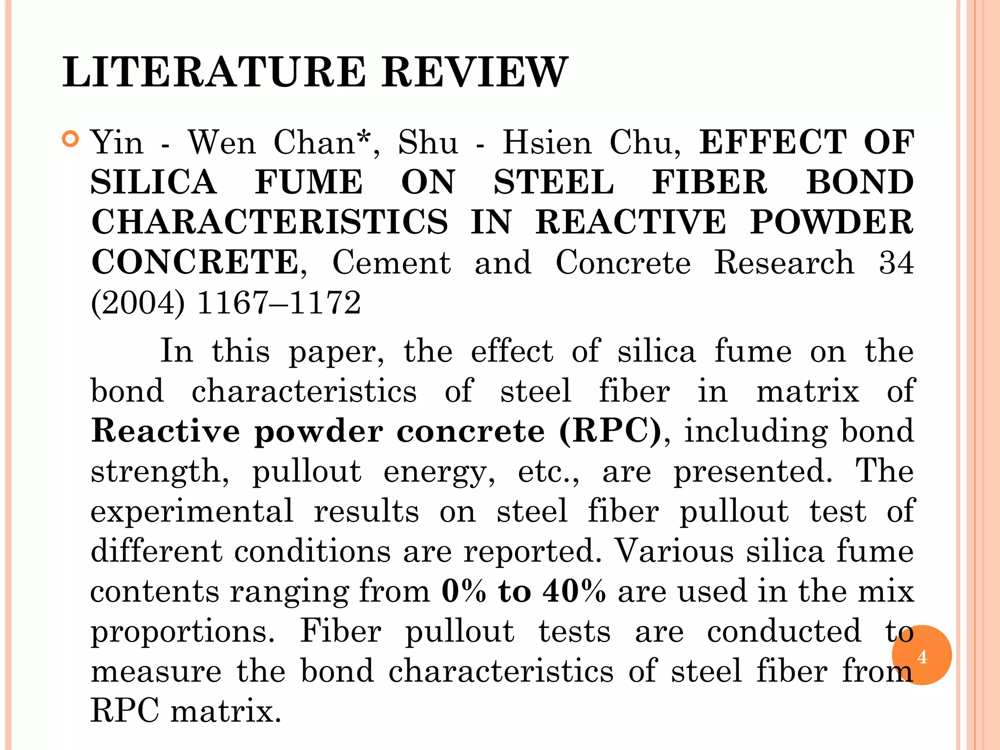
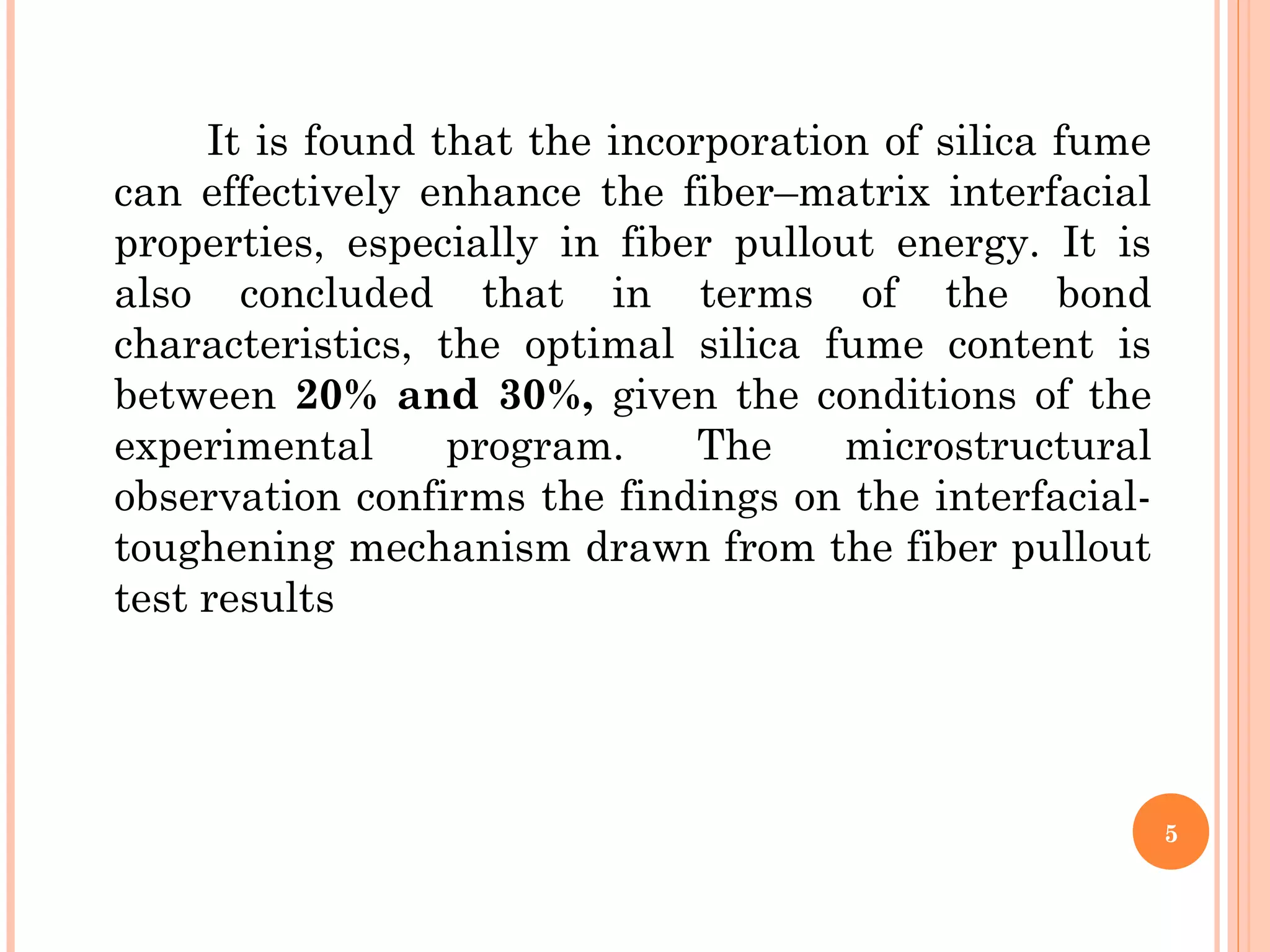
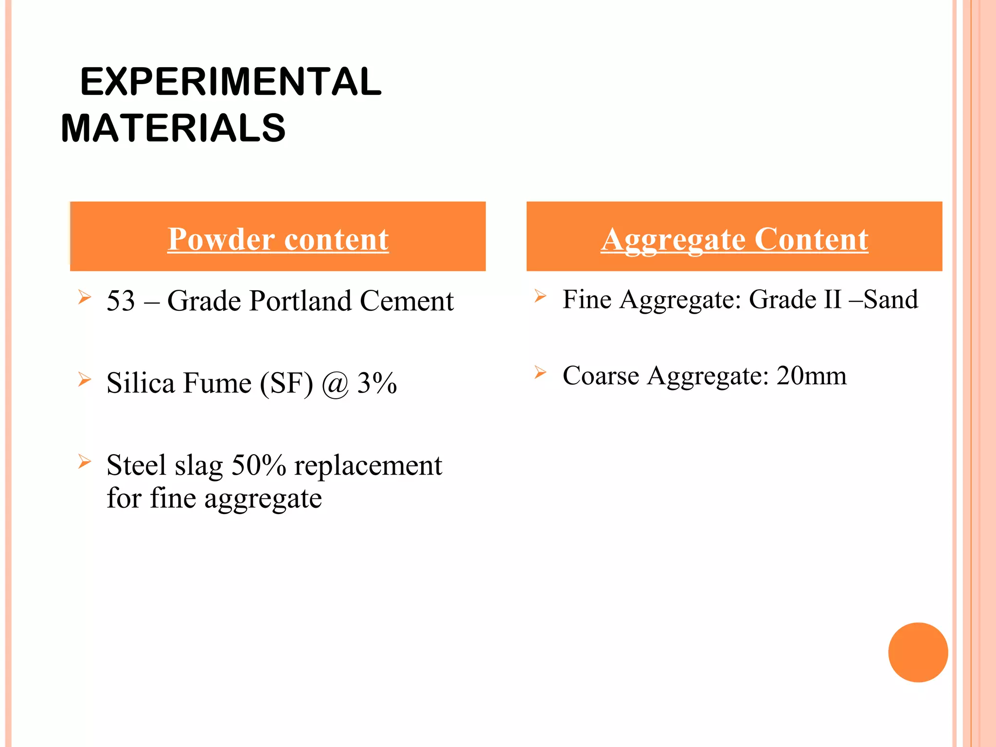
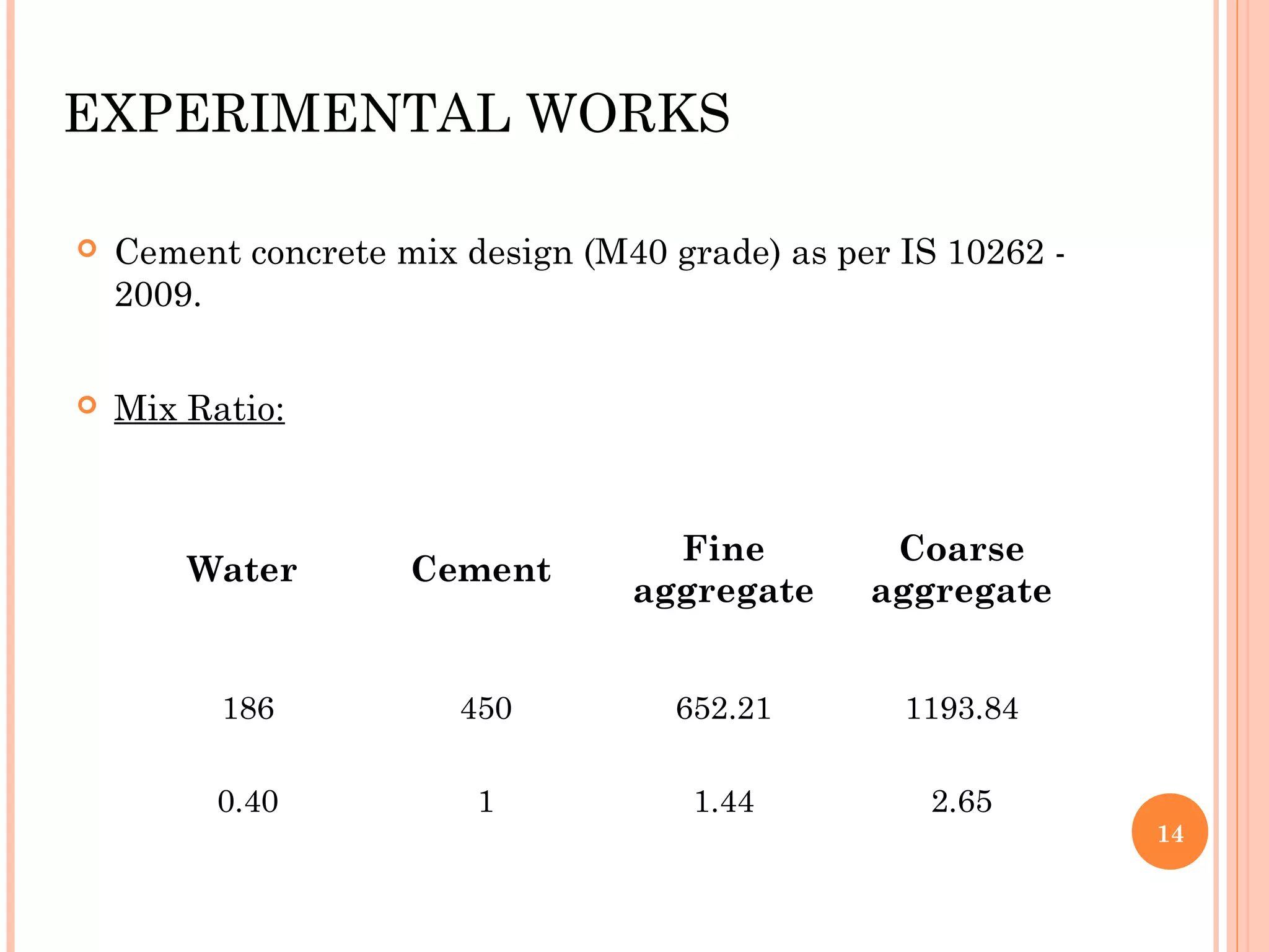
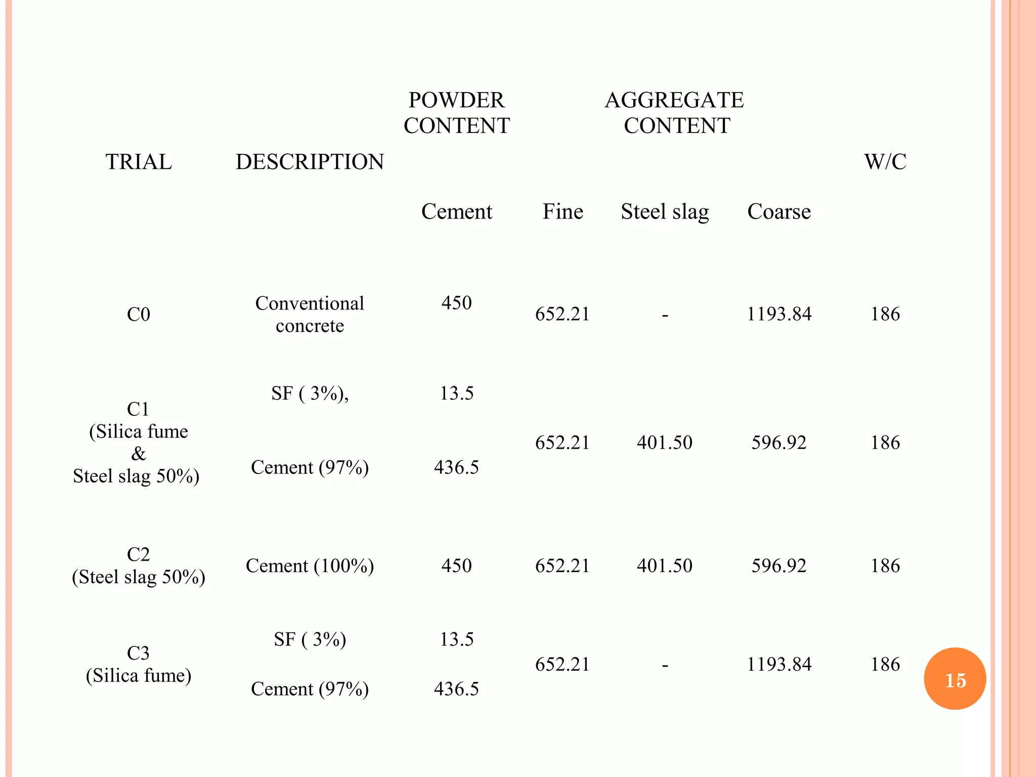
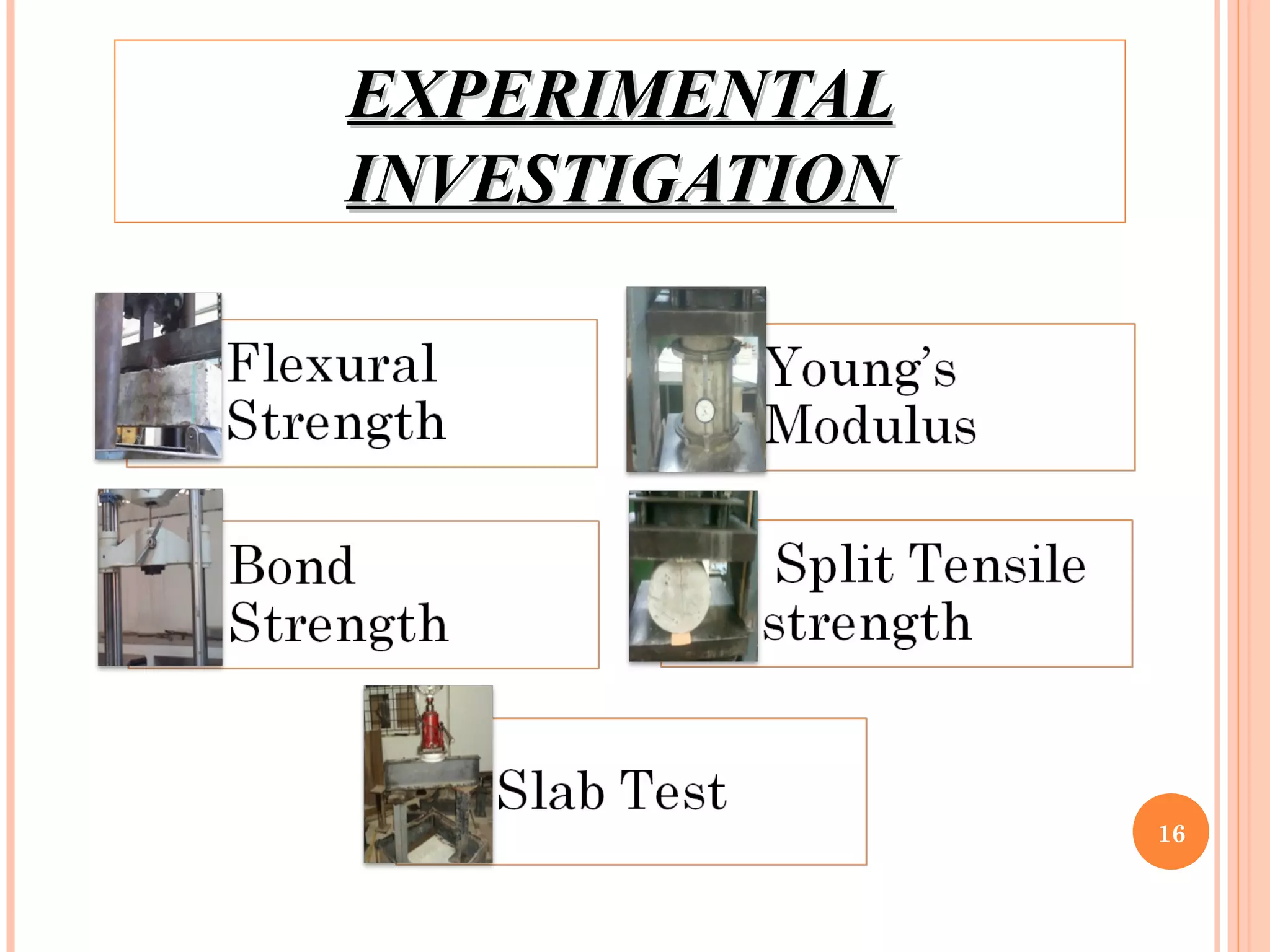
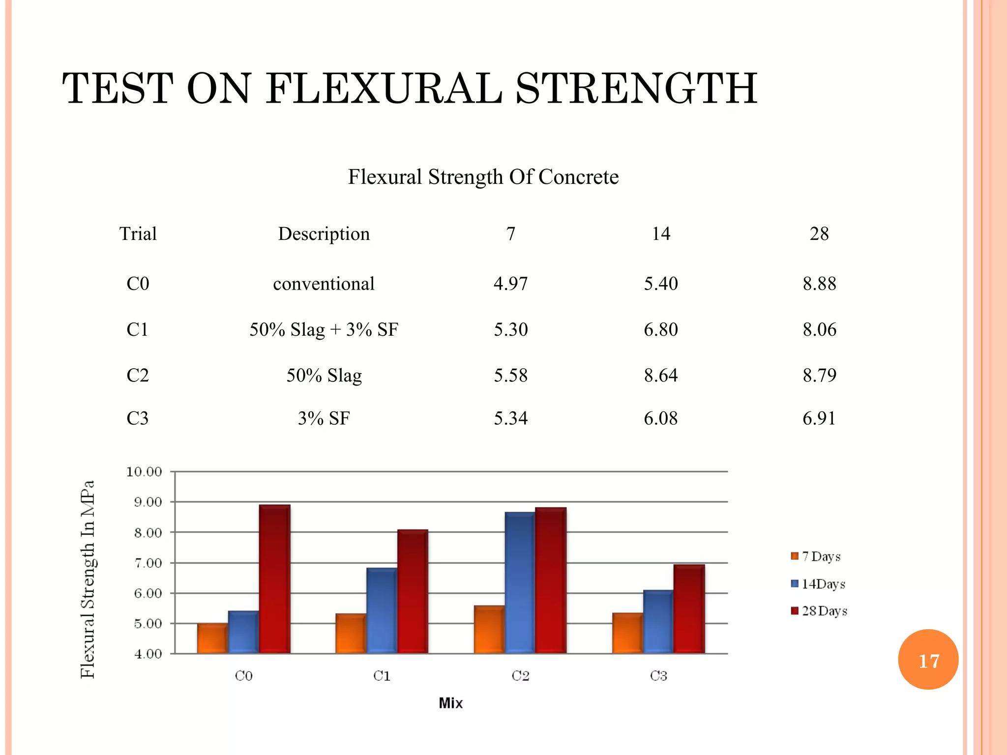
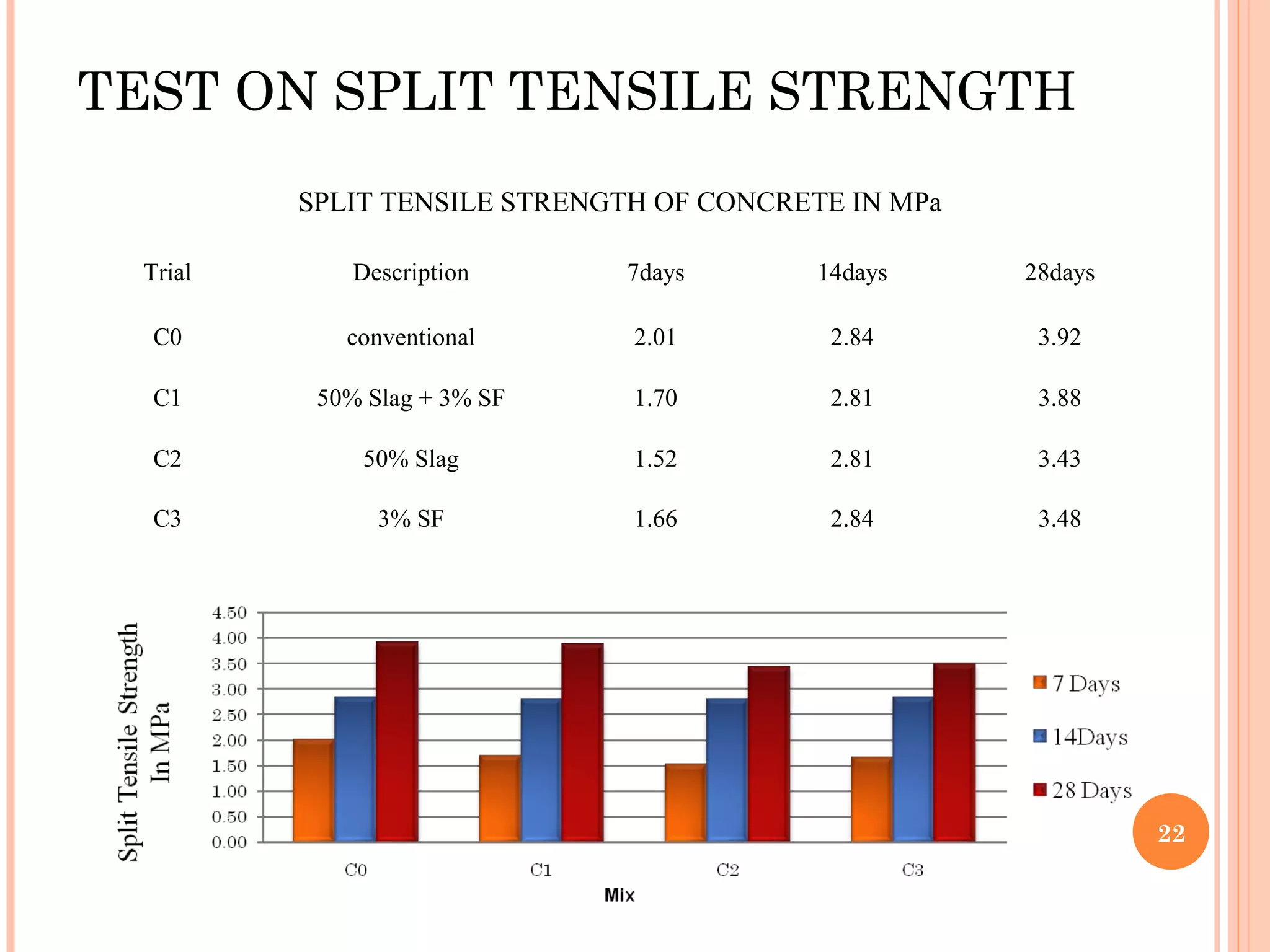
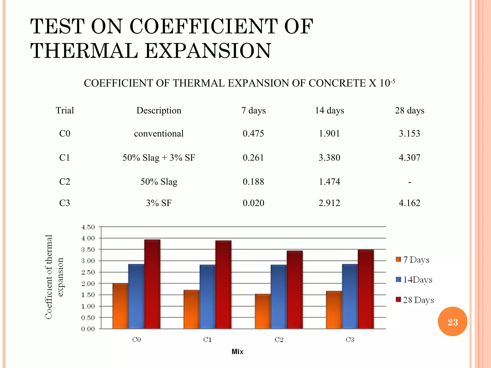
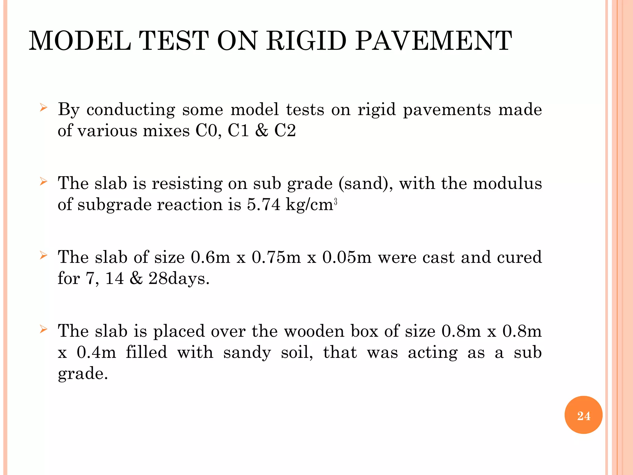
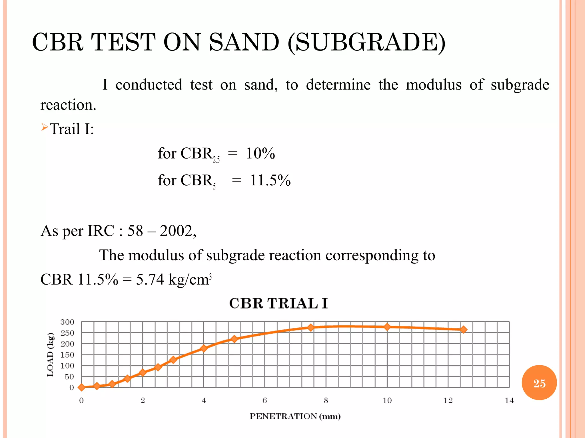


This document summarizes an experimental study on the behaviour and analysis of stress in rigid pavements. It begins with an introduction on rigid pavements and their load carrying capacity. The methodology section outlines the concrete mix designs that will be tested, including conventional concrete and mixes replacing cement with silica fume and steel slag. The literature review summarizes previous studies on the effects of silica fume and pavement boundary depth. The objectives and scope are then provided. The document outlines the materials and experimental works conducted, including tests on flexural strength, modulus of elasticity, Poisson's ratio, bond strength, split tensile strength, coefficient of thermal expansion, and model tests on rigid pavement slabs. The results of these tests are presented


