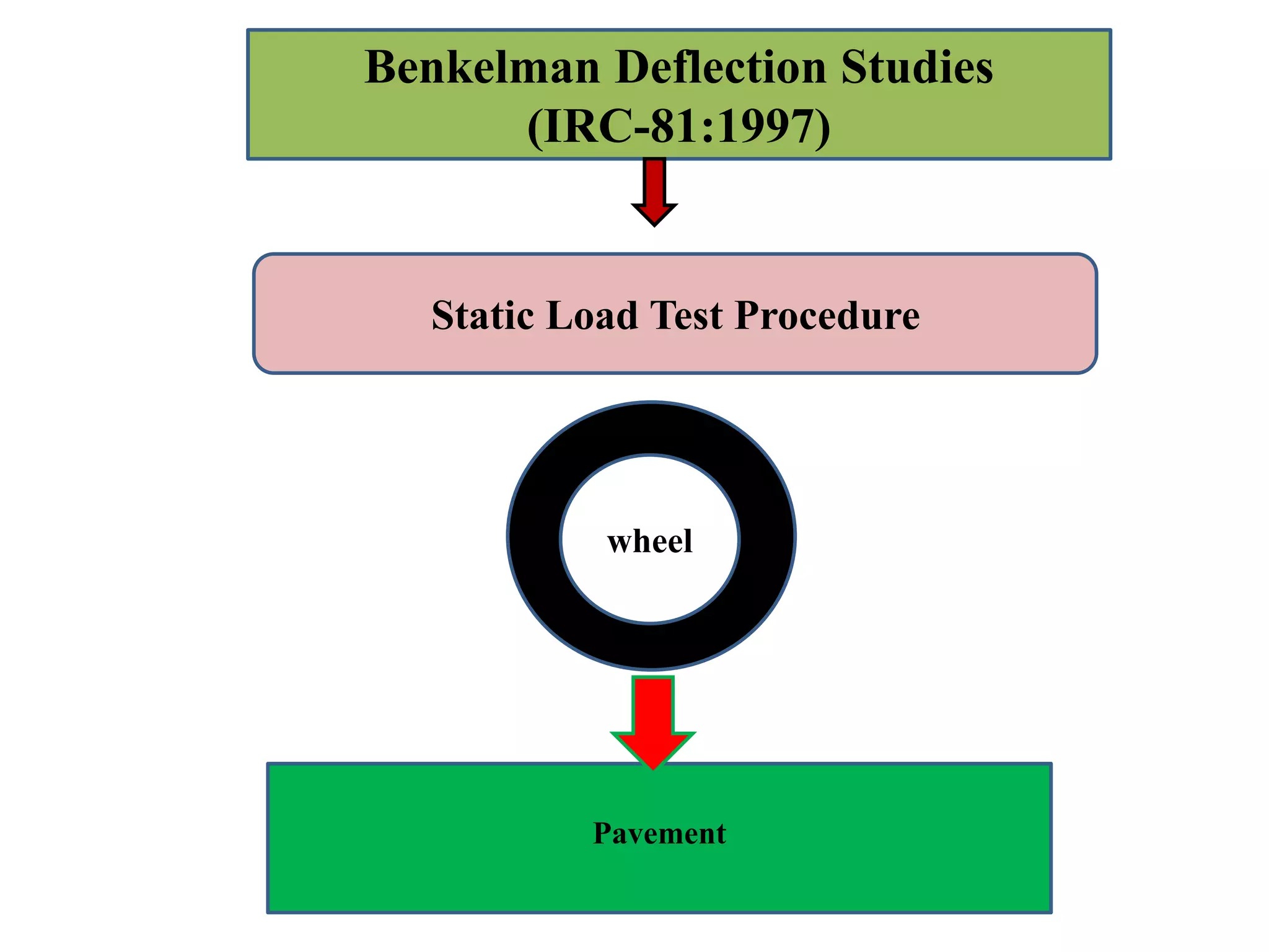
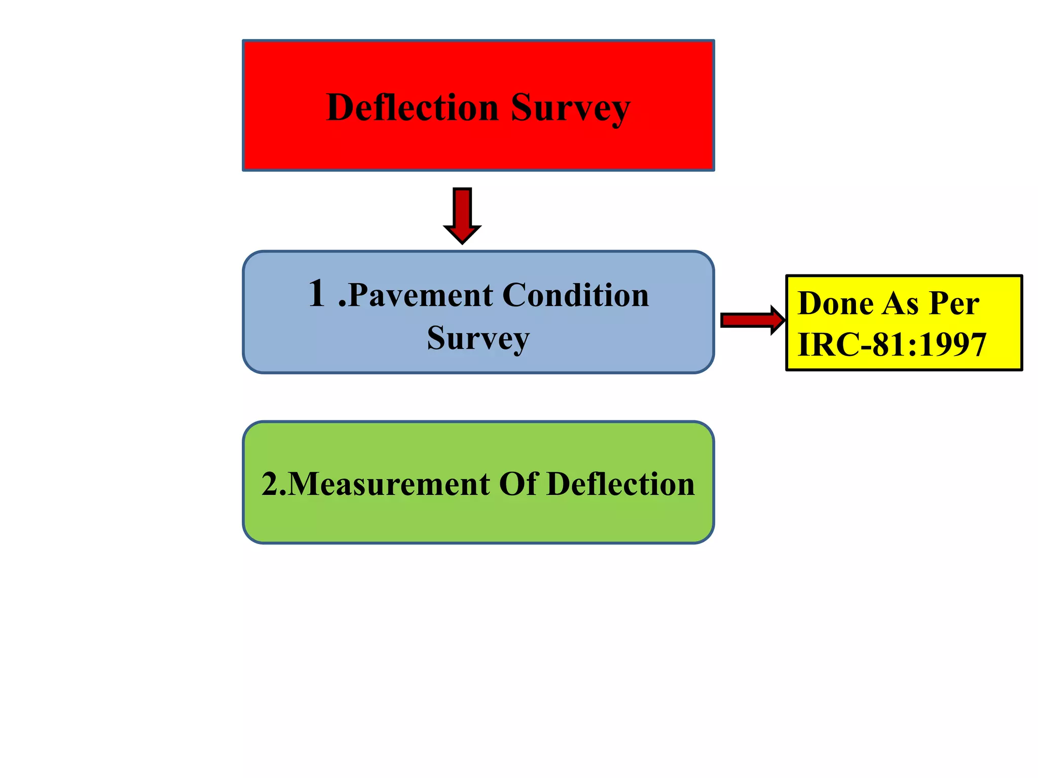
Benkelman Beam Deflection
Studies
Transportation Engineering
Section
Introduction
Benkelman Deflection Studies
(IRC-81:1997)
Pavement
Benkelman Deflection Studies
(IRC-81:1997)
Static Load Test Procedure
wheel
Benkelman Beam
Evaluation Of Structural
Capacity Of
Existing Pavement
Estimation And Design Of
Over Lay
For Strengthening Of Weak
Pavement
Need of Evaluation
• Pavement deteriorate functionally and
structurally with time due to traffic loading and
the different climatic condition.
• It is necessary to evaluate the condition of
existing pavement in terms of functionally and
structurally.
OVERLAY
• Pavement that do not have adequate structural
strength to carry out the projected future traffic
will have to be reinforced by providing
additional pavement layer
Sub Grade Soil Type And Its
Moisture Content
Compaction
Thickness
Quality Of Pavement Course
Drainage Condition Etc.
• This test procedure covers the determination of
the rebound deflection of a pavement under a
standard wheel load and tyre pressure.
Deflected Pavement Structure Bounce Back To
Original Shape
Deflected Surface Original Position
L
O
A
D
L
O
A
D
Load removed
1. Benkelman beam –
• Consist of slender beam of length 3.66 m.
• Pivoted at 2.44 m from probe.
• distance from pivot to dial gauge 1.22 m.
• Distance from pivot to front leg 25 cm.
• Distance from pivot to rear leg 1.66 m.
2. Loaded truck
• Weight of truck 12 t
• Rear axle load 8170 kg(dual tyre)
• Spacing between tyres 30-40 mm.
• Inflation pressure 5.6 kg/sq.cm.
3. Accessories –
• Tyre pressure measuring gauge.
• Thermometer(0-100 °c) with 1 ° division.
• Measuring tape.etc
Deflection Survey
1 .Pavement Condition
Survey
2.Measurement Of Deflection
Done As Per
IRC-81:1997
• Deflection Measurement –
• Point selection –
• 1 km road stretch .
• Minimum 10 points at 50 m interval .
• Location Of Point –
• Lane Width(m)
• Distance From Lane Edge(cm)
• Less than 3.5
• 60
• More than 3.5
• 90
A B C2.7 m 9 m
1. Select the points and marked.
2. The dual wheel of the truck is centered above the mark.
3. The probe of the benkelman beam is placed between the dual
tyres at the marked position.
4. Dial gauge is set at 1 cm.
5. Initial reading (s) is recorded when rate of deformation is less
than or equal to .025 mm/min.
6. Truck is slowly driven (at speed 8-10 m/s appr.)
at a distance of 2.7 m. and stopped.
7. Intermediate reading (I) is recorded.
8. Truck is driven forward a further 9 m.
9. Final reading (F) is recorded.
10.Pavement temperature is recorded atleast once
in each hour.
11.Tyre pressure is checked at 2-3 hrs interval
during a day.
•Find (S-I) & (S-F)
• If deferential Reading ≤ 0.025 mm (2.5 Divisions), then
True Rebound Deflection At Temp. T Is
XT = 2(S-F)
•If deferential reading ≥ 0.025mm, then
XT = 2(S-F) + 5.82 (I-F)
The pavement rebound deflection at a standard temperature
of 20°C shall be calculated
• Standard temp 35 °c.
• Correction is applied when min thickness of the pavement
is 40 mm.
• No correction for
– thin bituminous surfacing
– severe cracking in pavement
– bituminous layer is striped.
– Cold and high altitude regions where daily temp. < 20 °c
• Correction will be positive when temp blow stand.
Temperature
• Correction will be negative when temperature above
standard temperature.
• Correction factor is 0.01mm/ °c variation from standard
temp.
Over Lay Design For A Given Section Is Based Not
On Individual Deflection Value But On Statistical
Analysis Of All Measurements In The Section
1.Mean Deflection
2.Standard Deviation
3.Charecteristic Deflection
DC = M + 2S, For NH & SH
DC = M +S, for other roads
Concept of Over Lay
Undulated Surface Cracked Surface
Surface
Over Lay Surface
Benkelman beam deflection studies

Benkelman beam deflection studies

  • 1.
  • 2.
  • 3.
    Benkelman Deflection Studies (IRC-81:1997) Pavement BenkelmanDeflection Studies (IRC-81:1997) Static Load Test Procedure wheel
  • 4.
    Benkelman Beam Evaluation OfStructural Capacity Of Existing Pavement Estimation And Design Of Over Lay For Strengthening Of Weak Pavement
  • 5.
    Need of Evaluation •Pavement deteriorate functionally and structurally with time due to traffic loading and the different climatic condition. • It is necessary to evaluate the condition of existing pavement in terms of functionally and structurally.
  • 6.
    OVERLAY • Pavement thatdo not have adequate structural strength to carry out the projected future traffic will have to be reinforced by providing additional pavement layer
  • 8.
    Sub Grade SoilType And Its Moisture Content Compaction Thickness Quality Of Pavement Course Drainage Condition Etc.
  • 9.
    • This testprocedure covers the determination of the rebound deflection of a pavement under a standard wheel load and tyre pressure.
  • 10.
    Deflected Pavement StructureBounce Back To Original Shape Deflected Surface Original Position L O A D L O A D Load removed
  • 12.
    1. Benkelman beam– • Consist of slender beam of length 3.66 m. • Pivoted at 2.44 m from probe. • distance from pivot to dial gauge 1.22 m. • Distance from pivot to front leg 25 cm. • Distance from pivot to rear leg 1.66 m.
  • 14.
    2. Loaded truck •Weight of truck 12 t • Rear axle load 8170 kg(dual tyre) • Spacing between tyres 30-40 mm. • Inflation pressure 5.6 kg/sq.cm.
  • 15.
    3. Accessories – •Tyre pressure measuring gauge. • Thermometer(0-100 °c) with 1 ° division. • Measuring tape.etc
  • 17.
    Deflection Survey 1 .PavementCondition Survey 2.Measurement Of Deflection Done As Per IRC-81:1997
  • 18.
    • Deflection Measurement– • Point selection – • 1 km road stretch . • Minimum 10 points at 50 m interval . • Location Of Point – • Lane Width(m) • Distance From Lane Edge(cm) • Less than 3.5 • 60 • More than 3.5 • 90
  • 20.
    A B C2.7m 9 m
  • 22.
    1. Select thepoints and marked. 2. The dual wheel of the truck is centered above the mark. 3. The probe of the benkelman beam is placed between the dual tyres at the marked position.
  • 23.
    4. Dial gaugeis set at 1 cm. 5. Initial reading (s) is recorded when rate of deformation is less than or equal to .025 mm/min.
  • 24.
    6. Truck isslowly driven (at speed 8-10 m/s appr.) at a distance of 2.7 m. and stopped. 7. Intermediate reading (I) is recorded. 8. Truck is driven forward a further 9 m. 9. Final reading (F) is recorded. 10.Pavement temperature is recorded atleast once in each hour. 11.Tyre pressure is checked at 2-3 hrs interval during a day.
  • 26.
    •Find (S-I) &(S-F) • If deferential Reading ≤ 0.025 mm (2.5 Divisions), then True Rebound Deflection At Temp. T Is XT = 2(S-F) •If deferential reading ≥ 0.025mm, then XT = 2(S-F) + 5.82 (I-F) The pavement rebound deflection at a standard temperature of 20°C shall be calculated
  • 28.
    • Standard temp35 °c. • Correction is applied when min thickness of the pavement is 40 mm. • No correction for – thin bituminous surfacing – severe cracking in pavement – bituminous layer is striped. – Cold and high altitude regions where daily temp. < 20 °c • Correction will be positive when temp blow stand. Temperature • Correction will be negative when temperature above standard temperature. • Correction factor is 0.01mm/ °c variation from standard temp.
  • 30.
    Over Lay DesignFor A Given Section Is Based Not On Individual Deflection Value But On Statistical Analysis Of All Measurements In The Section 1.Mean Deflection 2.Standard Deviation 3.Charecteristic Deflection DC = M + 2S, For NH & SH DC = M +S, for other roads
  • 32.
    Concept of OverLay Undulated Surface Cracked Surface Surface Over Lay Surface