SlideShare a Scribd company logo
1 of 15
RC MEMBER ANALYSIS & DESIGN (EN1992-1-1:2004)
In accordance with EN1992-1-1:2004 incorporating Corrigenda January 2008 and the UK national annex
Tedds calculation version 3.0.00
ANALYSIS
Tedds calculation version 1.0.11
Geometry
Nodes
Node Co-ordinates Freedom Coordinate system Spring
X Z X Z Rot. Name Angle X Z Rot.
(m) (m) (°) (kN/m) (kN/m) kNm/°
1 0 0 Fixed Fixed Free 0 0 0 0
2 9 0 Fixed Fixed Free 0 0 0 0
Materials
Name Density Youngs Modulus Shear Modulus Thermal
Coefficient
(kg/m3
) kN/mm2
kN/mm2
°C-1
Concrete (C35 2500
Quartzite)
2500 34.0771462 14.1988109 0.00001
Sections
Name Area Moment of inertia Shear area
Major Minor Ay Az
(cm2
) (cm4
) (cm4
) (cm2
) (cm2
)
R 235x405 952 130092 43800 793 793
Elements
Element Length Nodes Section Material Releases Rotated
(m) Start End Start
moment
End
moment
Axial
1 9 1 2 R 235x405 Concrete (C35 2500
Quartzite)
Fixed Fixed Fixed
Members
Name Elements
Start End
Beam 1 1
Loading
Load cases
Name Enabled Self weight factor Patternable
Self Weight yes 1 no
Permanent yes 0 no
Imposed yes 0 no
Load combinations
Load combination Type Enabled Patterned
1.35G + 1.5ψ Strength yes no
Load combination: 1.35G + 1.5ψ0Q + 1.5ψ0S (Strength)
Load case Factor
Self Weight 1.35
Permanent 1.35
Imposed 1.05
Member point loads
Member Load case Position Load Orientation
Type Start
(kN)
Beam Imposed Absolute 3.5 m 0.8 GlobalZ
Beam Imposed Absolute 4.5 m 0.8 GlobalZ
Beam Imposed Absolute 5.5 m 0.8 GlobalZ
Member UDL loads
Member Load case Position Load Orientation
Type Start End
(kN/m)
Beam Permanent Absolute 0 m 9 m 2.63 GlobalZ
Beam Imposed Absolute 0 m 9 m 2.1 GlobalZ
Results
Total deflection
Member results
Load combination: 1.35G + 1.5ψ0Q + 1.5ψ0S (Strength)
Member Deflection Axial deflection
Pos Max Pos Min Pos Max Pos Min
(m) (mm) (m) (mm) (m) (mm) (m) (mm)
Beam 4.5 18.1 9 0 0 0 0 0
Node deflections
Load combination: 1.35G + 1.5ψ0Q + 1.5ψ0S (Strength)
Node Deflection Rotation Co-ordinate
system
X Z
(mm) (mm) (°)
1 0 0 0.36529
2 0 0 -0.36529
Total base reactions
Load case/combination Force
FX FZ
(kN) (kN)
1.35G + 1.5ψ0Q + 1.5ψ0S
(Strength)
0 82.6
Reactions
Load combination: 1.35G + 1.5ψ0Q + 1.5ψ0S (Strength)
Node Force Moment
Fx Fz My
(kN) (kN) (kNm)
1 0 41.3 0
2 0 41.3 0
Element end forces
Load combination: 1.35G + 1.5ψ0Q + 1.5ψ0S (Strength)
Element Length Nodes Axial force Shear force Moment
(m) Start/End (kN) (kN) (kNm)
1 9 1 0 -41.3 0
2 0 -41.3 0
Forces
;
Concrete details - Table 3.1. Strength and deformation characteristics for concrete
Concrete strength class; C35/45
Aggregate type; Quartzite
Aggregate adjustment factor - cl.3.1.3(2); AAF = 1.0
Characteristic compressive cylinder strength; fck = 35 N/mm2
Characteristic compressive cube strength; fck,cube = 45 N/mm2
Mean value of compressive cylinder strength; fcm = fck + 8 N/mm2 = 43 N/mm2
Mean value of axial tensile strength; fctm = 0.3 N/mm2 × (fck/ 1 N/mm2)2/3 = 3.2 N/mm2
Secant modulus of elasticity of concrete; Ecm = 22 kN/mm2×[fcm/10 N/mm2]0.3 × AAF = 34077 N/mm2
Ultimate strain - Table 3.1; εcu2 = 0.0035
Shortening strain - Table 3.1; εcu3 = 0.0035
Effective compression zone height factor; λ = 0.80
Effective strength factor; η = 1.00
Coefficient k1; k1 = 0.40
Coefficient k2; k2 = 1.0 × (0.6 + 0.0014 / εcu2) = 1.00
Coefficient k3; k3 = 0.40
Coefficient k4; k4 = 1.0 × (0.6 + 0.0014 / εcu2) = 1.00
Partial factor for concrete -Table 2.1N; γC = 1.50
Compressive strength coefficient - cl.3.1.6(1); αcc = 0.85
Design compressive concrete strength - exp.3.15; fcd = αcc × fck / γC = 19.8 N/mm2
Compressive strength coefficient - cl.3.1.6(1); αccw = 1.00
Design compressive concrete strength - exp.3.15; fcwd = αccw × fck / γC = 23.3 N/mm2
Maximum aggregate size; hagg = 20 mm
Monolithic simple support moment factor; β1 = 0.25
Reinforcement details
Characteristic yield strength of reinforcement; fyk = 500 N/mm2
Partial factor for reinforcing steel - Table 2.1N; γS = 1.15
Design yield strength of reinforcement; fyd = fyk / γS = 435 N/mm2
Nominal cover to reinforcement
Nominal cover to top reinforcement; cnom_t = 30 mm
Nominal cover to bottom reinforcement; cnom_b = 30 mm
Nominal cover to side reinforcement; cnom_s = 30 mm
Fire resistance
Standard fire resistance period; R = 60 min
Number of sides exposed to fire; 3
Minimum width of beam - EN1992-1-2 Table 5.5; bmin = 120 mm
Beam - Span 1
Rectangular section details
Section width; b = 235 mm
Section depth; h = 405 mm
PASS - Minimum dimensions for fire resistance met
Moment design
Zone 1 (0 mm - 2250 mm) Positive moment - section 6.1
Design bending moment; M = abs(Mm1_s1_z1_max_red) = 70.4 kNm
Effective depth of tension reinforcement; d = 349 mm
Redistribution ratio; δ = min(Mpos_red_z1 / Mpos_z1, 1) = 1.000
K = M / (b × d2 × fck) = 0.070
K' = (2 × η × αcc / γC) × (1 - λ × (δ - k1) / (2 × k2)) × (λ × (δ -
k1) / (2 × k2)) = 0.207
K' > K - No compression reinforcement is required
Lever arm; z = min(0.5 × d × [1 + (1 - 2 × K / (η × αcc / γC))0.5], 0.95 × d)
= 326 mm
Depth of neutral axis; x = 2 × (d - z) / λ = 58 mm
Area of tension reinforcement required; As,req = M / (fyd × z) = 497 mm2
Tension reinforcement provided; 2 × 32φ
Area of tension reinforcement provided; As,prov = 1608 mm2
Minimum area of reinforcement - exp.9.1N; As,min = max(0.26 × fctm / fyk, 0.0013) × b × d = 137 mm2
Maximum area of reinforcement - cl.9.2.1.1(3); As,max = 0.04 × b × h = 3807 mm2
PASS - Area of reinforcement provided is greater than area of reinforcement required
Crack control - Section 7.3
Maximum crack width; wk = 0.3 mm
Design value modulus of elasticity reinf - 3.2.7(4); Es = 200000 N/mm2
Mean value of concrete tensile strength; fct,eff = fctm = 3.2 N/mm2
Stress distribution coefficient; kc = 0.4
Non-uniform self-equilibrating stress coefficient; k = min(max(1 + (300 mm - min(h, b)) × 0.35 / 500 mm,
0.65), 1) = 1.00
Actual tension bar spacing; sbar = (b - (2 × (cnom_s + φm1_s1_z1_v) + φm1_s1_z1_b_L1 ×
Nm1_s1_z1_b_L1)) / (Nm1_s1_z1_b_L1 - 1) + φm1_s1_z1_b_L1 = 123 mm
Maximum stress permitted (Table 7.3N); σs = 302 N/mm2
Steel to concrete modulus of elast. ratio; αcr = Es / Ecm = 5.87
Distance of the Elastic NA from bottom of beam; y = (b × h2 / 2 + As,prov × (αcr - 1) × (h - d)) / (b × h + As,prov ×
(αcr - 1)) = 191 mm
Area of concrete in the tensile zone; Act = b × y = 44970 mm2
Minimum area of reinforcement required - exp.7.1; Asc,min = kc × k × fct,eff × Act / σs = 191 mm2
PASS - Area of tension reinforcement provided exceeds minimum required for crack control
Permanent load ratio; RPL = 0.65
Service stress in reinforcement; σsr = fyd × As,req / As,prov × RPL = 87 N/mm2
Maximum bar spacing - Tables 7.3N; sbar,max = 300 mm
PASS - Maximum bar spacing exceeds actual bar spacing for crack control
Zone 1 (0 mm - 2250 mm) Negative moment - section 6.1
Design bending moment; M = max(β1 × abs(Mm1_s1_max_red), abs(Mm1_s1_z1_min_red)) =
23.7 kNm
Effective depth of tension reinforcement; d = 353 mm
Redistribution ratio; δ = 1 = 1.000
K = M / (b × d2 × fck) = 0.023
K' = (2 × η × αcc / γC) × (1 - λ × (δ - k1) / (2 × k2)) × (λ × (δ -
k1) / (2 × k2)) = 0.207
K' > K - No compression reinforcement is required
Lever arm; z = min(0.5 × d × [1 + (1 - 2 × K / (η × αcc / γC))0.5], 0.95 × d)
= 335 mm
Depth of neutral axis; x = 2 × (d - z) / λ = 44 mm
Area of tension reinforcement required; As,req = M / (fyd × z) = 163 mm2
Tension reinforcement provided; 2 × 25φ
Area of tension reinforcement provided; As,prov = 982 mm2
Minimum area of reinforcement - exp.9.1N; As,min = max(0.26 × fctm / fyk, 0.0013) × b × d = 138 mm2
Maximum area of reinforcement - cl.9.2.1.1(3); As,max = 0.04 × b × h = 3807 mm2
PASS - Area of reinforcement provided is greater than area of reinforcement required
Crack control - Section 7.3
Maximum crack width; wk = 0.3 mm
Design value modulus of elasticity reinf - 3.2.7(4); Es = 200000 N/mm2
Mean value of concrete tensile strength; fct,eff = fctm = 3.2 N/mm2
Stress distribution coefficient; kc = 0.4
Non-uniform self-equilibrating stress coefficient; k = min(max(1 + (300 mm - min(h, b)) × 0.35 / 500 mm,
0.65), 1) = 1.00
Actual tension bar spacing; sbar = (b - (2 × (cnom_s + φm1_s1_z1_v) + φm1_s1_z1_t_L1 ×
Nm1_s1_z1_t_L1)) / (Nm1_s1_z1_t_L1 - 1) + φm1_s1_z1_t_L1 = 130 mm
Maximum stress permitted (Table 7.3N); σs = 296 N/mm2
Steel to concrete modulus of elast. ratio; αcr = Es / Ecm = 5.87
Distance of the Elastic NA from bottom of beam; y = (b × h2 / 2 + As,prov × (αcr - 1) × (h - d)) / (b × h + As,prov ×
(αcr - 1)) = 195 mm
Area of concrete in the tensile zone; Act = b × y = 45902 mm2
Minimum area of reinforcement required - exp.7.1; Asc,min = kc × k × fct,eff × Act / σs = 199 mm2
PASS - Area of tension reinforcement provided exceeds minimum required for crack control
Permanent load ratio; RPL = 0.65
Service stress in reinforcement; σsr = fyd × As,req / As,prov × RPL = 47 N/mm2
Maximum bar spacing - Tables 7.3N; sbar,max = 300 mm
PASS - Maximum bar spacing exceeds actual bar spacing for crack control
Minimum bar spacing (Section 8.2)
Top bar spacing; stop = (b - (2 × (cnom_s + φm1_s1_z1_v) + φm1_s1_z1_t_L1 ×
Nm1_s1_z1_t_L1)) / (Nm1_s1_z1_t_L1 - 1) = 105.0 mm
Minimum allowable top bar spacing; stop,min = max(φm1_s1_z1_t_L1 × ks1, hagg + ks2, 20mm) = 25.0
mm
PASS - Actual bar spacing exceeds minimum allowable
Bottom bar spacing; sbot = (b - (2 × (cnom_s + φm1_s1_z1_v) + φm1_s1_z1_b_L1 ×
Nm1_s1_z1_b_L1)) / (Nm1_s1_z1_b_L1 - 1) = 91.0 mm
Minimum allowable bottom bar spacing; sbot,min = max(φm1_s1_z1_b_L1 × ks1, hagg + ks2, 20mm) = 32.0
mm
PASS - Actual bar spacing exceeds minimum allowable
Zone 2 (2250 mm - 6750 mm) Positive moment - section 6.1
Design bending moment; M = abs(Mm1_s1_z2_max_red) = 94.9 kNm
Effective depth of tension reinforcement; d = 349 mm
Redistribution ratio; δ = min(Mpos_red_z2 / Mpos_z2, 1) = 1.000
K = M / (b × d2 × fck) = 0.095
K' = (2 × η × αcc / γC) × (1 - λ × (δ - k1) / (2 × k2)) × (λ × (δ -
k1) / (2 × k2)) = 0.207
K' > K - No compression reinforcement is required
Lever arm; z = min(0.5 × d × [1 + (1 - 2 × K / (η × αcc / γC))0.5], 0.95 × d)
= 317 mm
Depth of neutral axis; x = 2 × (d - z) / λ = 80 mm
Area of tension reinforcement required; As,req = M / (fyd × z) = 689 mm2
Tension reinforcement provided; 2 × 32φ
Area of tension reinforcement provided; As,prov = 1608 mm2
Minimum area of reinforcement - exp.9.1N; As,min = max(0.26 × fctm / fyk, 0.0013) × b × d = 137 mm2
Maximum area of reinforcement - cl.9.2.1.1(3); As,max = 0.04 × b × h = 3807 mm2
PASS - Area of reinforcement provided is greater than area of reinforcement required
Crack control - Section 7.3
Maximum crack width; wk = 0.3 mm
Design value modulus of elasticity reinf - 3.2.7(4); Es = 200000 N/mm2
Mean value of concrete tensile strength; fct,eff = fctm = 3.2 N/mm2
Stress distribution coefficient; kc = 0.4
Non-uniform self-equilibrating stress coefficient; k = min(max(1 + (300 mm - min(h, b)) × 0.35 / 500 mm,
0.65), 1) = 1.00
Actual tension bar spacing; sbar = (b - (2 × (cnom_s + φm1_s1_z2_v) + φm1_s1_z2_b_L1 ×
Nm1_s1_z2_b_L1 + φm1_s1_z1_b_L1 × Nm1_s1_z1_b_L1)) /
((Nm1_s1_z2_b_L1 + Nm1_s1_z1_b_L1) - 1) + φm1_s1_z1_b_L1 = 123 mm
Maximum stress permitted (Table 7.3N); σs = 302 N/mm2
Steel to concrete modulus of elast. ratio; αcr = Es / Ecm = 5.87
Distance of the Elastic NA from bottom of beam; y = (b × h2 / 2 + As,prov × (αcr - 1) × (h - d)) / (b × h + As,prov ×
(αcr - 1)) = 191 mm
Area of concrete in the tensile zone; Act = b × y = 44970 mm2
Minimum area of reinforcement required - exp.7.1; Asc,min = kc × k × fct,eff × Act / σs = 191 mm2
PASS - Area of tension reinforcement provided exceeds minimum required for crack control
Permanent load ratio; RPL = 0.65
Service stress in reinforcement; σsr = fyd × As,req / As,prov × RPL = 121 N/mm2
Maximum bar spacing - Tables 7.3N; sbar,max = 300 mm
PASS - Maximum bar spacing exceeds actual bar spacing for crack control
Deflection control - Section 7.4
Reference reinforcement ratio; ρm0 = (fck / 1 N/mm2)0.5 / 1000 = 0.00592
Required tension reinforcement ratio; ρm = As,req / (b × d) = 0.00840
Required compression reinforcement ratio; ρ'm = As2,req / (b × d) = 0.00000
Structural system factor - Table 7.4N; Kb = 1.0
Basic allowable span to depth ratio ; span_to_depthbasic = Kb × [11 + 1.5 × (fck / 1 N/mm2)0.5 ×
ρm0 / (ρm - ρ'm) + (fck / 1 N/mm2)0.5 × (ρ'm / ρm0)0.5 / 12] =
17.249
Reinforcement factor - exp.7.17; Ks = min(As,prov / As,req × 500 N/mm2 / fyk, 1.5) = 1.500
Flange width factor; F1 = 1 = 1.000
Long span supporting brittle partition factor; F2 = 1 = 1.000
Allowable span to depth ratio; span_to_depthallow = min(span_to_depthbasic × Ks × F1 × F2,
40 × Kb) = 25.873
Actual span to depth ratio; span_to_depthactual = Lm1_s1 / d = 25.788
PASS - Actual span to depth ratio is within the allowable limit
Minimum bar spacing (Section 8.2)
Top bar spacing; stop = (b - (2 × (cnom_s + φm1_s1_z2_v) + φm1_s1_z2_t_L1 ×
Nm1_s1_z2_t_L1)) / (Nm1_s1_z2_t_L1 - 1) = 105.0 mm
Minimum allowable top bar spacing; stop,min = max(φm1_s1_z2_t_L1 × ks1, hagg + ks2, 20mm) = 25.0
mm
PASS - Actual bar spacing exceeds minimum allowable
Bottom bar spacing; sbot = (b - (2 × (cnom_s + φm1_s1_z2_v) + φm1_s1_z2_b_L1 ×
Nm1_s1_z2_b_L1 + φm1_s1_z1_b_L1 × Nm1_s1_z1_b_L1)) /
((Nm1_s1_z2_b_L1 + Nm1_s1_z1_b_L1) - 1) = 91.0 mm
Minimum allowable bottom bar spacing; sbot,min = max(φm1_s1_z1_b_L1 × ks1, hagg + ks2, 20mm) = 32.0
mm
PASS - Actual bar spacing exceeds minimum allowable
Zone 3 (6750 mm - 9000 mm) Positive moment - section 6.1
Design bending moment; M = abs(Mm1_s1_z3_max_red) = 70.4 kNm
Effective depth of tension reinforcement; d = 349 mm
Redistribution ratio; δ = min(Mpos_red_z3 / Mpos_z3, 1) = 1.000
K = M / (b × d2 × fck) = 0.070
K' = (2 × η × αcc / γC) × (1 - λ × (δ - k1) / (2 × k2)) × (λ × (δ -
k1) / (2 × k2)) = 0.207
K' > K - No compression reinforcement is required
Lever arm; z = min(0.5 × d × [1 + (1 - 2 × K / (η × αcc / γC))0.5], 0.95 × d)
= 326 mm
Depth of neutral axis; x = 2 × (d - z) / λ = 58 mm
Area of tension reinforcement required; As,req = M / (fyd × z) = 497 mm2
Tension reinforcement provided; 2 × 32φ
Area of tension reinforcement provided; As,prov = 1608 mm2
Minimum area of reinforcement - exp.9.1N; As,min = max(0.26 × fctm / fyk, 0.0013) × b × d = 137 mm2
Maximum area of reinforcement - cl.9.2.1.1(3); As,max = 0.04 × b × h = 3807 mm2
PASS - Area of reinforcement provided is greater than area of reinforcement required
Crack control - Section 7.3
Maximum crack width; wk = 0.3 mm
Design value modulus of elasticity reinf - 3.2.7(4); Es = 200000 N/mm2
Mean value of concrete tensile strength; fct,eff = fctm = 3.2 N/mm2
Stress distribution coefficient; kc = 0.4
Non-uniform self-equilibrating stress coefficient; k = min(max(1 + (300 mm - min(h, b)) × 0.35 / 500 mm,
0.65), 1) = 1.00
Actual tension bar spacing; sbar = (b - (2 × (cnom_s + φm1_s1_z3_v) + φm1_s1_z3_b_L1 ×
Nm1_s1_z3_b_L1)) / (Nm1_s1_z3_b_L1 - 1) + φm1_s1_z3_b_L1 = 123 mm
Maximum stress permitted (Table 7.3N); σs = 302 N/mm2
Steel to concrete modulus of elast. ratio; αcr = Es / Ecm = 5.87
Distance of the Elastic NA from bottom of beam; y = (b × h2 / 2 + As,prov × (αcr - 1) × (h - d)) / (b × h + As,prov ×
(αcr - 1)) = 191 mm
Area of concrete in the tensile zone; Act = b × y = 44970 mm2
Minimum area of reinforcement required - exp.7.1; Asc,min = kc × k × fct,eff × Act / σs = 191 mm2
PASS - Area of tension reinforcement provided exceeds minimum required for crack control
Permanent load ratio; RPL = 0.65
Service stress in reinforcement; σsr = fyd × As,req / As,prov × RPL = 87 N/mm2
Maximum bar spacing - Tables 7.3N; sbar,max = 300 mm
PASS - Maximum bar spacing exceeds actual bar spacing for crack control
Zone 3 (6750 mm - 9000 mm) Negative moment - section 6.1
Design bending moment; M = max(β1 × abs(Mm1_s1_max_red), abs(Mm1_s1_z3_min_red)) =
23.7 kNm
Effective depth of tension reinforcement; d = 353 mm
Redistribution ratio; δ = 1 = 1.000
K = M / (b × d2 × fck) = 0.023
K' = (2 × η × αcc / γC) × (1 - λ × (δ - k1) / (2 × k2)) × (λ × (δ -
k1) / (2 × k2)) = 0.207
K' > K - No compression reinforcement is required
Lever arm; z = min(0.5 × d × [1 + (1 - 2 × K / (η × αcc / γC))0.5], 0.95 × d)
= 335 mm
Depth of neutral axis; x = 2 × (d - z) / λ = 44 mm
Area of tension reinforcement required; As,req = M / (fyd × z) = 163 mm2
Tension reinforcement provided; 2 × 25φ
Area of tension reinforcement provided; As,prov = 982 mm2
Minimum area of reinforcement - exp.9.1N; As,min = max(0.26 × fctm / fyk, 0.0013) × b × d = 138 mm2
Maximum area of reinforcement - cl.9.2.1.1(3); As,max = 0.04 × b × h = 3807 mm2
PASS - Area of reinforcement provided is greater than area of reinforcement required
Crack control - Section 7.3
Maximum crack width; wk = 0.3 mm
Design value modulus of elasticity reinf - 3.2.7(4); Es = 200000 N/mm2
Mean value of concrete tensile strength; fct,eff = fctm = 3.2 N/mm2
Stress distribution coefficient; kc = 0.4
Non-uniform self-equilibrating stress coefficient; k = min(max(1 + (300 mm - min(h, b)) × 0.35 / 500 mm,
0.65), 1) = 1.00
Actual tension bar spacing; sbar = (b - (2 × (cnom_s + φm1_s1_z3_v) + φm1_s1_z3_t_L1 ×
Nm1_s1_z3_t_L1)) / (Nm1_s1_z3_t_L1 - 1) + φm1_s1_z3_t_L1 = 130 mm
Maximum stress permitted (Table 7.3N); σs = 296 N/mm2
Steel to concrete modulus of elast. ratio; αcr = Es / Ecm = 5.87
Distance of the Elastic NA from bottom of beam; y = (b × h2 / 2 + As,prov × (αcr - 1) × (h - d)) / (b × h + As,prov ×
(αcr - 1)) = 195 mm
Area of concrete in the tensile zone; Act = b × y = 45902 mm2
Minimum area of reinforcement required - exp.7.1; Asc,min = kc × k × fct,eff × Act / σs = 199 mm2
PASS - Area of tension reinforcement provided exceeds minimum required for crack control
Permanent load ratio; RPL = 0.65
Service stress in reinforcement; σsr = fyd × As,req / As,prov × RPL = 47 N/mm2
Maximum bar spacing - Tables 7.3N; sbar,max = 300 mm
PASS - Maximum bar spacing exceeds actual bar spacing for crack control
Minimum bar spacing (Section 8.2)
Top bar spacing; stop = (b - (2 × (cnom_s + φm1_s1_z3_v) + φm1_s1_z3_t_L1 ×
Nm1_s1_z3_t_L1)) / (Nm1_s1_z3_t_L1 - 1) = 105.0 mm
Minimum allowable top bar spacing; stop,min = max(φm1_s1_z3_t_L1 × ks1, hagg + ks2, 20mm) = 25.0
mm
PASS - Actual bar spacing exceeds minimum allowable
Bottom bar spacing; sbot = (b - (2 × (cnom_s + φm1_s1_z3_v) + φm1_s1_z3_b_L1 ×
Nm1_s1_z3_b_L1)) / (Nm1_s1_z3_b_L1 - 1) = 91.0 mm
Minimum allowable bottom bar spacing; sbot,min = max(φm1_s1_z3_b_L1 × ks1, hagg + ks2, 20mm) = 32.0
mm
PASS - Actual bar spacing exceeds minimum allowable
Shear design
Angle of comp. shear strut for maximum shear; θmax = 45 deg
Strength reduction factor - cl.6.2.3(3); v1 = 0.6 × (1 - fck / 250 N/mm2) = 0.516
Compression chord coefficient - cl.6.2.3(3); αcw = 1.00
Minimum area of shear reinforcement - exp.9.5N; Asv,min = 0.08 N/mm2 × b × (fck / 1 N/mm2)0.5 / fyk = 222
mm2/m
Zone 1 (0 mm - 2250 mm) shear - section 6.2
Design shear force at support ; VEd,max = max(abs(Vz1_max), abs(Vz1_red_max)) = 41 kN
Min lever arm in shear zone; z = 405 mm
Maximum design shear resistance - exp.6.9; VRd,max = αcw × b × z × v1 × fcwd / (cot(θmax) + tan(θmax)) = 573
kN
PASS - Design shear force at support is less than maximum design shear resistance
Design shear force at 405mm from support; VEd = 38 kN
Design shear stress; vEd = VEd / (b × z) = 0.396 N/mm2
Angle of concrete compression strut - cl.6.2.3; θ = min(max(0.5 × Asin[min(2 × vEd / (αcw × fcd × v1),1)], 21.8
deg), 45deg) = 21.8 deg
Area of shear reinforcement required - exp.6.8; Asv,des = vEd × b / (fyd × cot(θ)) = 86 mm2/m
Area of shear reinforcement required; Asv,req = max(Asv,min, Asv,des) = 222 mm2/m
Shear reinforcement provided; 2 × 10 legs @ 200 c/c
Area of shear reinforcement provided; Asv,prov = 785 mm2/m
PASS - Area of shear reinforcement provided exceeds minimum required
Maximum longitudinal spacing - exp.9.6N; svl,max = 0.75 × d = 304 mm
PASS - Longitudinal spacing of shear reinforcement provided is less than maximum
Zone 2 (2250 mm - 6750 mm) shear - section 6.2
Design shear force within zone; VEd = 21 kN
Design shear stress; vEd = VEd / (b × z) = 0.224 N/mm2
Angle of concrete compression strut - cl.6.2.3; θ = min(max(0.5 × Asin[min(2 × vEd / (αcw × fcd × v1),1)], 21.8
deg), 45deg) = 21.8 deg
Area of shear reinforcement required - exp.6.8; Asv,des = vEd × b / (fyd × cot(θ)) = 48 mm2/m
Area of shear reinforcement required; Asv,req = max(Asv,min, Asv,des) = 222 mm2/m
Shear reinforcement provided; 2 × 10 legs @ 200 c/c
Area of shear reinforcement provided; Asv,prov = 785 mm2/m
PASS - Area of shear reinforcement provided exceeds minimum required
Maximum longitudinal spacing - exp.9.6N; svl,max = 0.75 × d = 304 mm
PASS - Longitudinal spacing of shear reinforcement provided is less than maximum
Zone 3 (6750 mm - 9000 mm) shear - section 6.2
Design shear force at support ; VEd,max = max(abs(Vz3_max), abs(Vz3_red_max)) = 41 kN
Min lever arm in shear zone; z = 405 mm
Maximum design shear resistance - exp.6.9; VRd,max = αcw × b × z × v1 × fcwd / (cot(θmax) + tan(θmax)) = 573
kN
PASS - Design shear force at support is less than maximum design shear resistance
Design shear force at 405mm from support; VEd = 38 kN
Design shear stress; vEd = VEd / (b × z) = 0.396 N/mm2
Angle of concrete compression strut - cl.6.2.3; θ = min(max(0.5 × Asin[min(2 × vEd / (αcw × fcd × v1),1)], 21.8
deg), 45deg) = 21.8 deg
Area of shear reinforcement required - exp.6.8; Asv,des = vEd × b / (fyd × cot(θ)) = 86 mm2/m
Area of shear reinforcement required; Asv,req = max(Asv,min, Asv,des) = 222 mm2/m
Shear reinforcement provided; 2 × 10 legs @ 200 c/c
Area of shear reinforcement provided; Asv,prov = 785 mm2/m
PASS - Area of shear reinforcement provided exceeds minimum required
Maximum longitudinal spacing - exp.9.6N; svl,max = 0.75 × d = 304 mm
PASS - Longitudinal spacing of shear reinforcement provided is less than maximum

More Related Content

What's hot

Assignment [4] machining with solutions
Assignment [4]  machining with solutionsAssignment [4]  machining with solutions
Assignment [4] machining with solutions
moradmoro
 
Torsion of circular shafts
Torsion of circular shaftsTorsion of circular shafts
Torsion of circular shafts
aero103
 
the role of exchange bias in domain dynamics control
the role of exchange bias in domain dynamics controlthe role of exchange bias in domain dynamics control
the role of exchange bias in domain dynamics control
Andrea Benassi
 
Trabajo 1 densidad de muros y cargas verticales
Trabajo 1   densidad de muros y cargas verticalesTrabajo 1   densidad de muros y cargas verticales
Trabajo 1 densidad de muros y cargas verticales
David Rojas
 
Supersymmetric U(1)_{B-L} x U(1)_R model with dark matter, muon g-2 and Z' ma...
Supersymmetric U(1)_{B-L} x U(1)_R model with dark matter, muon g-2 and Z' ma...Supersymmetric U(1)_{B-L} x U(1)_R model with dark matter, muon g-2 and Z' ma...
Supersymmetric U(1)_{B-L} x U(1)_R model with dark matter, muon g-2 and Z' ma...
Özer Özdal
 

What's hot (20)

Free pier uls section check
Free pier uls section checkFree pier uls section check
Free pier uls section check
 
Solution manual 4 6
Solution manual 4 6Solution manual 4 6
Solution manual 4 6
 
Assignment [4] machining with solutions
Assignment [4]  machining with solutionsAssignment [4]  machining with solutions
Assignment [4] machining with solutions
 
Chapter 07 in som
Chapter 07 in som Chapter 07 in som
Chapter 07 in som
 
Slab panel desing sheet (1) (2)
Slab panel desing sheet (1) (2)Slab panel desing sheet (1) (2)
Slab panel desing sheet (1) (2)
 
H.w. #7
H.w. #7H.w. #7
H.w. #7
 
Torsion of circular shafts
Torsion of circular shaftsTorsion of circular shafts
Torsion of circular shafts
 
Solution manual 1 3
Solution manual 1 3Solution manual 1 3
Solution manual 1 3
 
the role of exchange bias in domain dynamics control
the role of exchange bias in domain dynamics controlthe role of exchange bias in domain dynamics control
the role of exchange bias in domain dynamics control
 
Design and optimization of parts of a suspension system
Design and optimization of parts of a suspension systemDesign and optimization of parts of a suspension system
Design and optimization of parts of a suspension system
 
Solution manual 7 8
Solution manual 7 8Solution manual 7 8
Solution manual 7 8
 
Solution manual 16
Solution manual 16Solution manual 16
Solution manual 16
 
PERHITUNGAN TULANGAN LONGITUDINAL BALOK BETON BERTULANG RANGKAP
PERHITUNGAN TULANGAN LONGITUDINAL BALOK BETON BERTULANG RANGKAPPERHITUNGAN TULANGAN LONGITUDINAL BALOK BETON BERTULANG RANGKAP
PERHITUNGAN TULANGAN LONGITUDINAL BALOK BETON BERTULANG RANGKAP
 
1 perhitungan-balok
1 perhitungan-balok1 perhitungan-balok
1 perhitungan-balok
 
1 reinforced concrete lectures-t-beam2
1 reinforced concrete lectures-t-beam21 reinforced concrete lectures-t-beam2
1 reinforced concrete lectures-t-beam2
 
Solution Manul for Structural Analysis in SI Units 10th Edition by Russell Hi...
Solution Manul for Structural Analysis in SI Units 10th Edition by Russell Hi...Solution Manul for Structural Analysis in SI Units 10th Edition by Russell Hi...
Solution Manul for Structural Analysis in SI Units 10th Edition by Russell Hi...
 
Solution manual for mechanics of materials 10th edition hibbeler sample
Solution manual for mechanics of materials 10th edition hibbeler  sampleSolution manual for mechanics of materials 10th edition hibbeler  sample
Solution manual for mechanics of materials 10th edition hibbeler sample
 
Understanding graphene nano-ribbon manipulation
Understanding graphene nano-ribbon manipulationUnderstanding graphene nano-ribbon manipulation
Understanding graphene nano-ribbon manipulation
 
Trabajo 1 densidad de muros y cargas verticales
Trabajo 1   densidad de muros y cargas verticalesTrabajo 1   densidad de muros y cargas verticales
Trabajo 1 densidad de muros y cargas verticales
 
Supersymmetric U(1)_{B-L} x U(1)_R model with dark matter, muon g-2 and Z' ma...
Supersymmetric U(1)_{B-L} x U(1)_R model with dark matter, muon g-2 and Z' ma...Supersymmetric U(1)_{B-L} x U(1)_R model with dark matter, muon g-2 and Z' ma...
Supersymmetric U(1)_{B-L} x U(1)_R model with dark matter, muon g-2 and Z' ma...
 

Viewers also liked

04. joist (kuliah iv)
04. joist (kuliah iv)04. joist (kuliah iv)
04. joist (kuliah iv)
yadipermadi
 
Flow Chart - One Way Joist Construction
Flow Chart - One Way Joist ConstructionFlow Chart - One Way Joist Construction
Flow Chart - One Way Joist Construction
Qamar Uz Zaman
 
Hollow block and ribbed slabs
Hollow block and ribbed slabsHollow block and ribbed slabs
Hollow block and ribbed slabs
Mohamed Mohsen
 
Beam and slab design
Beam and slab designBeam and slab design
Beam and slab design
Ivan Ferrer
 

Viewers also liked (20)

CVDEC14
CVDEC14CVDEC14
CVDEC14
 
Sachpazis RC Slab Analysis and Design in accordance with EN 1992 1-1 2004-Two...
Sachpazis RC Slab Analysis and Design in accordance with EN 1992 1-1 2004-Two...Sachpazis RC Slab Analysis and Design in accordance with EN 1992 1-1 2004-Two...
Sachpazis RC Slab Analysis and Design in accordance with EN 1992 1-1 2004-Two...
 
Ce1302 design of rc elements
Ce1302 design of rc elementsCe1302 design of rc elements
Ce1302 design of rc elements
 
Chapter 13
Chapter 13Chapter 13
Chapter 13
 
Mathcad 17-slab design
Mathcad   17-slab designMathcad   17-slab design
Mathcad 17-slab design
 
04. joist (kuliah iv)
04. joist (kuliah iv)04. joist (kuliah iv)
04. joist (kuliah iv)
 
Flow Chart - One Way Joist Construction
Flow Chart - One Way Joist ConstructionFlow Chart - One Way Joist Construction
Flow Chart - One Way Joist Construction
 
Design and Detailing of RC structures
Design and Detailing of RC structuresDesign and Detailing of RC structures
Design and Detailing of RC structures
 
Construction Insitu Rc Suspended Floors Using Bm Bending Moment Formula Maths
Construction  Insitu Rc Suspended Floors Using Bm Bending Moment Formula MathsConstruction  Insitu Rc Suspended Floors Using Bm Bending Moment Formula Maths
Construction Insitu Rc Suspended Floors Using Bm Bending Moment Formula Maths
 
Lec.9 strength design method doubly reinforced beams
Lec.9   strength design method doubly reinforced beamsLec.9   strength design method doubly reinforced beams
Lec.9 strength design method doubly reinforced beams
 
Lec.1 introduction
Lec.1   introductionLec.1   introduction
Lec.1 introduction
 
Lec.2 statically determinate structures & statically indeterminate struct...
Lec.2 statically determinate structures & statically indeterminate struct...Lec.2 statically determinate structures & statically indeterminate struct...
Lec.2 statically determinate structures & statically indeterminate struct...
 
Hollow Block
Hollow Block Hollow Block
Hollow Block
 
One way slab design 10.01.03.162
One way slab design 10.01.03.162One way slab design 10.01.03.162
One way slab design 10.01.03.162
 
BT 1: Concrete Hollow Blocks
BT 1: Concrete Hollow BlocksBT 1: Concrete Hollow Blocks
BT 1: Concrete Hollow Blocks
 
Hollow block and ribbed slabs
Hollow block and ribbed slabsHollow block and ribbed slabs
Hollow block and ribbed slabs
 
Design of reinforced concrete structures(one way slab)+with calculation.
Design of reinforced concrete structures(one way slab)+with calculation.Design of reinforced concrete structures(one way slab)+with calculation.
Design of reinforced concrete structures(one way slab)+with calculation.
 
Design of One-Way Slab
Design of One-Way SlabDesign of One-Way Slab
Design of One-Way Slab
 
ONE WAY SLAB DESIGN
ONE WAY SLAB DESIGNONE WAY SLAB DESIGN
ONE WAY SLAB DESIGN
 
Beam and slab design
Beam and slab designBeam and slab design
Beam and slab design
 

Similar to RC member analysis and design

Worked example extract_flat_slabs
Worked example extract_flat_slabsWorked example extract_flat_slabs
Worked example extract_flat_slabs
luantvconst
 
Beams design and analysis
Beams design and analysisBeams design and analysis
Beams design and analysis
Aman Adam
 
Worked example extract_flat_slabs
Worked example extract_flat_slabsWorked example extract_flat_slabs
Worked example extract_flat_slabs
Luan Truong Van
 

Similar to RC member analysis and design (20)

Sachpazis: Two-way RC Slab Slab Analysis & Design (EN1992-1-1:2004) example
Sachpazis: Two-way RC Slab Slab Analysis & Design (EN1992-1-1:2004) exampleSachpazis: Two-way RC Slab Slab Analysis & Design (EN1992-1-1:2004) example
Sachpazis: Two-way RC Slab Slab Analysis & Design (EN1992-1-1:2004) example
 
Padeye calculation example
Padeye calculation examplePadeye calculation example
Padeye calculation example
 
3F TO 5F BEAM DESIGN SUMMARY.pdf
3F TO 5F BEAM DESIGN SUMMARY.pdf3F TO 5F BEAM DESIGN SUMMARY.pdf
3F TO 5F BEAM DESIGN SUMMARY.pdf
 
3F TO 5F BEAM DESIGN SUMMARY.pdf
3F TO 5F BEAM DESIGN SUMMARY.pdf3F TO 5F BEAM DESIGN SUMMARY.pdf
3F TO 5F BEAM DESIGN SUMMARY.pdf
 
Singly Reinforce Concrete
Singly Reinforce ConcreteSingly Reinforce Concrete
Singly Reinforce Concrete
 
Analysis and Design of Residential building.pptx
Analysis and Design of Residential building.pptxAnalysis and Design of Residential building.pptx
Analysis and Design of Residential building.pptx
 
Panel h
Panel hPanel h
Panel h
 
singly-reinforced-beam.ppt
singly-reinforced-beam.pptsingly-reinforced-beam.ppt
singly-reinforced-beam.ppt
 
Design of SR Framed str beam.ppt
Design of SR Framed str beam.pptDesign of SR Framed str beam.ppt
Design of SR Framed str beam.ppt
 
Structural Design
Structural DesignStructural Design
Structural Design
 
Chapter 12
Chapter 12Chapter 12
Chapter 12
 
96729556 hoja-de-calculo-para-zapatas
96729556 hoja-de-calculo-para-zapatas96729556 hoja-de-calculo-para-zapatas
96729556 hoja-de-calculo-para-zapatas
 
SINGLY REINFORCED BEAM
SINGLY REINFORCED BEAM SINGLY REINFORCED BEAM
SINGLY REINFORCED BEAM
 
PLANNING,ANALYSIS,DESIGNING AND ESTIMATION OF CANTILEVER RESIDENTIAL BUILDING
PLANNING,ANALYSIS,DESIGNING AND ESTIMATION OF CANTILEVER RESIDENTIAL BUILDINGPLANNING,ANALYSIS,DESIGNING AND ESTIMATION OF CANTILEVER RESIDENTIAL BUILDING
PLANNING,ANALYSIS,DESIGNING AND ESTIMATION OF CANTILEVER RESIDENTIAL BUILDING
 
Worked example extract_flat_slabs
Worked example extract_flat_slabsWorked example extract_flat_slabs
Worked example extract_flat_slabs
 
Autodesk robot structural analysis professional 2013
Autodesk robot structural analysis professional 2013Autodesk robot structural analysis professional 2013
Autodesk robot structural analysis professional 2013
 
RCC BMD
RCC BMDRCC BMD
RCC BMD
 
Beams design and analysis
Beams design and analysisBeams design and analysis
Beams design and analysis
 
Worked example extract_flat_slabs
Worked example extract_flat_slabsWorked example extract_flat_slabs
Worked example extract_flat_slabs
 
09-Strength of Gusset Plate (Steel Structural Design & Prof. Shehab Mourad)
09-Strength of Gusset Plate (Steel Structural Design & Prof. Shehab Mourad)09-Strength of Gusset Plate (Steel Structural Design & Prof. Shehab Mourad)
09-Strength of Gusset Plate (Steel Structural Design & Prof. Shehab Mourad)
 

RC member analysis and design

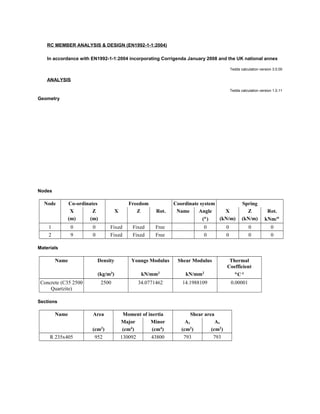
  • 1. RC MEMBER ANALYSIS & DESIGN (EN1992-1-1:2004) In accordance with EN1992-1-1:2004 incorporating Corrigenda January 2008 and the UK national annex Tedds calculation version 3.0.00 ANALYSIS Tedds calculation version 1.0.11 Geometry Nodes Node Co-ordinates Freedom Coordinate system Spring X Z X Z Rot. Name Angle X Z Rot. (m) (m) (°) (kN/m) (kN/m) kNm/° 1 0 0 Fixed Fixed Free 0 0 0 0 2 9 0 Fixed Fixed Free 0 0 0 0 Materials Name Density Youngs Modulus Shear Modulus Thermal Coefficient (kg/m3 ) kN/mm2 kN/mm2 °C-1 Concrete (C35 2500 Quartzite) 2500 34.0771462 14.1988109 0.00001 Sections Name Area Moment of inertia Shear area Major Minor Ay Az (cm2 ) (cm4 ) (cm4 ) (cm2 ) (cm2 ) R 235x405 952 130092 43800 793 793
  • 2. Elements Element Length Nodes Section Material Releases Rotated (m) Start End Start moment End moment Axial 1 9 1 2 R 235x405 Concrete (C35 2500 Quartzite) Fixed Fixed Fixed Members Name Elements Start End Beam 1 1 Loading
  • 3. Load cases Name Enabled Self weight factor Patternable Self Weight yes 1 no Permanent yes 0 no Imposed yes 0 no Load combinations Load combination Type Enabled Patterned 1.35G + 1.5ψ Strength yes no Load combination: 1.35G + 1.5ψ0Q + 1.5ψ0S (Strength) Load case Factor Self Weight 1.35 Permanent 1.35 Imposed 1.05 Member point loads Member Load case Position Load Orientation Type Start (kN) Beam Imposed Absolute 3.5 m 0.8 GlobalZ Beam Imposed Absolute 4.5 m 0.8 GlobalZ Beam Imposed Absolute 5.5 m 0.8 GlobalZ Member UDL loads Member Load case Position Load Orientation Type Start End (kN/m) Beam Permanent Absolute 0 m 9 m 2.63 GlobalZ Beam Imposed Absolute 0 m 9 m 2.1 GlobalZ
  • 4. Results Total deflection Member results Load combination: 1.35G + 1.5ψ0Q + 1.5ψ0S (Strength) Member Deflection Axial deflection Pos Max Pos Min Pos Max Pos Min (m) (mm) (m) (mm) (m) (mm) (m) (mm) Beam 4.5 18.1 9 0 0 0 0 0 Node deflections Load combination: 1.35G + 1.5ψ0Q + 1.5ψ0S (Strength) Node Deflection Rotation Co-ordinate system X Z (mm) (mm) (°) 1 0 0 0.36529 2 0 0 -0.36529 Total base reactions Load case/combination Force FX FZ (kN) (kN) 1.35G + 1.5ψ0Q + 1.5ψ0S (Strength) 0 82.6
  • 5. Reactions Load combination: 1.35G + 1.5ψ0Q + 1.5ψ0S (Strength) Node Force Moment Fx Fz My (kN) (kN) (kNm) 1 0 41.3 0 2 0 41.3 0 Element end forces Load combination: 1.35G + 1.5ψ0Q + 1.5ψ0S (Strength) Element Length Nodes Axial force Shear force Moment (m) Start/End (kN) (kN) (kNm) 1 9 1 0 -41.3 0 2 0 -41.3 0 Forces
  • 6. ; Concrete details - Table 3.1. Strength and deformation characteristics for concrete Concrete strength class; C35/45 Aggregate type; Quartzite Aggregate adjustment factor - cl.3.1.3(2); AAF = 1.0 Characteristic compressive cylinder strength; fck = 35 N/mm2 Characteristic compressive cube strength; fck,cube = 45 N/mm2 Mean value of compressive cylinder strength; fcm = fck + 8 N/mm2 = 43 N/mm2 Mean value of axial tensile strength; fctm = 0.3 N/mm2 × (fck/ 1 N/mm2)2/3 = 3.2 N/mm2 Secant modulus of elasticity of concrete; Ecm = 22 kN/mm2×[fcm/10 N/mm2]0.3 × AAF = 34077 N/mm2 Ultimate strain - Table 3.1; εcu2 = 0.0035 Shortening strain - Table 3.1; εcu3 = 0.0035 Effective compression zone height factor; λ = 0.80 Effective strength factor; η = 1.00 Coefficient k1; k1 = 0.40 Coefficient k2; k2 = 1.0 × (0.6 + 0.0014 / εcu2) = 1.00 Coefficient k3; k3 = 0.40 Coefficient k4; k4 = 1.0 × (0.6 + 0.0014 / εcu2) = 1.00 Partial factor for concrete -Table 2.1N; γC = 1.50 Compressive strength coefficient - cl.3.1.6(1); αcc = 0.85 Design compressive concrete strength - exp.3.15; fcd = αcc × fck / γC = 19.8 N/mm2 Compressive strength coefficient - cl.3.1.6(1); αccw = 1.00 Design compressive concrete strength - exp.3.15; fcwd = αccw × fck / γC = 23.3 N/mm2 Maximum aggregate size; hagg = 20 mm Monolithic simple support moment factor; β1 = 0.25 Reinforcement details Characteristic yield strength of reinforcement; fyk = 500 N/mm2 Partial factor for reinforcing steel - Table 2.1N; γS = 1.15 Design yield strength of reinforcement; fyd = fyk / γS = 435 N/mm2 Nominal cover to reinforcement Nominal cover to top reinforcement; cnom_t = 30 mm
  • 7. Nominal cover to bottom reinforcement; cnom_b = 30 mm Nominal cover to side reinforcement; cnom_s = 30 mm Fire resistance Standard fire resistance period; R = 60 min Number of sides exposed to fire; 3 Minimum width of beam - EN1992-1-2 Table 5.5; bmin = 120 mm Beam - Span 1 Rectangular section details Section width; b = 235 mm Section depth; h = 405 mm PASS - Minimum dimensions for fire resistance met Moment design Zone 1 (0 mm - 2250 mm) Positive moment - section 6.1 Design bending moment; M = abs(Mm1_s1_z1_max_red) = 70.4 kNm
  • 8. Effective depth of tension reinforcement; d = 349 mm Redistribution ratio; δ = min(Mpos_red_z1 / Mpos_z1, 1) = 1.000 K = M / (b × d2 × fck) = 0.070 K' = (2 × η × αcc / γC) × (1 - λ × (δ - k1) / (2 × k2)) × (λ × (δ - k1) / (2 × k2)) = 0.207 K' > K - No compression reinforcement is required Lever arm; z = min(0.5 × d × [1 + (1 - 2 × K / (η × αcc / γC))0.5], 0.95 × d) = 326 mm Depth of neutral axis; x = 2 × (d - z) / λ = 58 mm Area of tension reinforcement required; As,req = M / (fyd × z) = 497 mm2 Tension reinforcement provided; 2 × 32φ Area of tension reinforcement provided; As,prov = 1608 mm2 Minimum area of reinforcement - exp.9.1N; As,min = max(0.26 × fctm / fyk, 0.0013) × b × d = 137 mm2 Maximum area of reinforcement - cl.9.2.1.1(3); As,max = 0.04 × b × h = 3807 mm2 PASS - Area of reinforcement provided is greater than area of reinforcement required Crack control - Section 7.3 Maximum crack width; wk = 0.3 mm Design value modulus of elasticity reinf - 3.2.7(4); Es = 200000 N/mm2 Mean value of concrete tensile strength; fct,eff = fctm = 3.2 N/mm2 Stress distribution coefficient; kc = 0.4 Non-uniform self-equilibrating stress coefficient; k = min(max(1 + (300 mm - min(h, b)) × 0.35 / 500 mm, 0.65), 1) = 1.00 Actual tension bar spacing; sbar = (b - (2 × (cnom_s + φm1_s1_z1_v) + φm1_s1_z1_b_L1 × Nm1_s1_z1_b_L1)) / (Nm1_s1_z1_b_L1 - 1) + φm1_s1_z1_b_L1 = 123 mm Maximum stress permitted (Table 7.3N); σs = 302 N/mm2 Steel to concrete modulus of elast. ratio; αcr = Es / Ecm = 5.87 Distance of the Elastic NA from bottom of beam; y = (b × h2 / 2 + As,prov × (αcr - 1) × (h - d)) / (b × h + As,prov × (αcr - 1)) = 191 mm Area of concrete in the tensile zone; Act = b × y = 44970 mm2 Minimum area of reinforcement required - exp.7.1; Asc,min = kc × k × fct,eff × Act / σs = 191 mm2 PASS - Area of tension reinforcement provided exceeds minimum required for crack control Permanent load ratio; RPL = 0.65 Service stress in reinforcement; σsr = fyd × As,req / As,prov × RPL = 87 N/mm2 Maximum bar spacing - Tables 7.3N; sbar,max = 300 mm PASS - Maximum bar spacing exceeds actual bar spacing for crack control Zone 1 (0 mm - 2250 mm) Negative moment - section 6.1 Design bending moment; M = max(β1 × abs(Mm1_s1_max_red), abs(Mm1_s1_z1_min_red)) = 23.7 kNm Effective depth of tension reinforcement; d = 353 mm Redistribution ratio; δ = 1 = 1.000 K = M / (b × d2 × fck) = 0.023
  • 9. K' = (2 × η × αcc / γC) × (1 - λ × (δ - k1) / (2 × k2)) × (λ × (δ - k1) / (2 × k2)) = 0.207 K' > K - No compression reinforcement is required Lever arm; z = min(0.5 × d × [1 + (1 - 2 × K / (η × αcc / γC))0.5], 0.95 × d) = 335 mm Depth of neutral axis; x = 2 × (d - z) / λ = 44 mm Area of tension reinforcement required; As,req = M / (fyd × z) = 163 mm2 Tension reinforcement provided; 2 × 25φ Area of tension reinforcement provided; As,prov = 982 mm2 Minimum area of reinforcement - exp.9.1N; As,min = max(0.26 × fctm / fyk, 0.0013) × b × d = 138 mm2 Maximum area of reinforcement - cl.9.2.1.1(3); As,max = 0.04 × b × h = 3807 mm2 PASS - Area of reinforcement provided is greater than area of reinforcement required Crack control - Section 7.3 Maximum crack width; wk = 0.3 mm Design value modulus of elasticity reinf - 3.2.7(4); Es = 200000 N/mm2 Mean value of concrete tensile strength; fct,eff = fctm = 3.2 N/mm2 Stress distribution coefficient; kc = 0.4 Non-uniform self-equilibrating stress coefficient; k = min(max(1 + (300 mm - min(h, b)) × 0.35 / 500 mm, 0.65), 1) = 1.00 Actual tension bar spacing; sbar = (b - (2 × (cnom_s + φm1_s1_z1_v) + φm1_s1_z1_t_L1 × Nm1_s1_z1_t_L1)) / (Nm1_s1_z1_t_L1 - 1) + φm1_s1_z1_t_L1 = 130 mm Maximum stress permitted (Table 7.3N); σs = 296 N/mm2 Steel to concrete modulus of elast. ratio; αcr = Es / Ecm = 5.87 Distance of the Elastic NA from bottom of beam; y = (b × h2 / 2 + As,prov × (αcr - 1) × (h - d)) / (b × h + As,prov × (αcr - 1)) = 195 mm Area of concrete in the tensile zone; Act = b × y = 45902 mm2 Minimum area of reinforcement required - exp.7.1; Asc,min = kc × k × fct,eff × Act / σs = 199 mm2 PASS - Area of tension reinforcement provided exceeds minimum required for crack control Permanent load ratio; RPL = 0.65 Service stress in reinforcement; σsr = fyd × As,req / As,prov × RPL = 47 N/mm2 Maximum bar spacing - Tables 7.3N; sbar,max = 300 mm PASS - Maximum bar spacing exceeds actual bar spacing for crack control Minimum bar spacing (Section 8.2) Top bar spacing; stop = (b - (2 × (cnom_s + φm1_s1_z1_v) + φm1_s1_z1_t_L1 × Nm1_s1_z1_t_L1)) / (Nm1_s1_z1_t_L1 - 1) = 105.0 mm Minimum allowable top bar spacing; stop,min = max(φm1_s1_z1_t_L1 × ks1, hagg + ks2, 20mm) = 25.0 mm PASS - Actual bar spacing exceeds minimum allowable Bottom bar spacing; sbot = (b - (2 × (cnom_s + φm1_s1_z1_v) + φm1_s1_z1_b_L1 × Nm1_s1_z1_b_L1)) / (Nm1_s1_z1_b_L1 - 1) = 91.0 mm Minimum allowable bottom bar spacing; sbot,min = max(φm1_s1_z1_b_L1 × ks1, hagg + ks2, 20mm) = 32.0 mm PASS - Actual bar spacing exceeds minimum allowable
  • 10. Zone 2 (2250 mm - 6750 mm) Positive moment - section 6.1 Design bending moment; M = abs(Mm1_s1_z2_max_red) = 94.9 kNm Effective depth of tension reinforcement; d = 349 mm Redistribution ratio; δ = min(Mpos_red_z2 / Mpos_z2, 1) = 1.000 K = M / (b × d2 × fck) = 0.095 K' = (2 × η × αcc / γC) × (1 - λ × (δ - k1) / (2 × k2)) × (λ × (δ - k1) / (2 × k2)) = 0.207 K' > K - No compression reinforcement is required Lever arm; z = min(0.5 × d × [1 + (1 - 2 × K / (η × αcc / γC))0.5], 0.95 × d) = 317 mm Depth of neutral axis; x = 2 × (d - z) / λ = 80 mm Area of tension reinforcement required; As,req = M / (fyd × z) = 689 mm2 Tension reinforcement provided; 2 × 32φ Area of tension reinforcement provided; As,prov = 1608 mm2 Minimum area of reinforcement - exp.9.1N; As,min = max(0.26 × fctm / fyk, 0.0013) × b × d = 137 mm2 Maximum area of reinforcement - cl.9.2.1.1(3); As,max = 0.04 × b × h = 3807 mm2 PASS - Area of reinforcement provided is greater than area of reinforcement required Crack control - Section 7.3 Maximum crack width; wk = 0.3 mm Design value modulus of elasticity reinf - 3.2.7(4); Es = 200000 N/mm2 Mean value of concrete tensile strength; fct,eff = fctm = 3.2 N/mm2 Stress distribution coefficient; kc = 0.4 Non-uniform self-equilibrating stress coefficient; k = min(max(1 + (300 mm - min(h, b)) × 0.35 / 500 mm, 0.65), 1) = 1.00 Actual tension bar spacing; sbar = (b - (2 × (cnom_s + φm1_s1_z2_v) + φm1_s1_z2_b_L1 × Nm1_s1_z2_b_L1 + φm1_s1_z1_b_L1 × Nm1_s1_z1_b_L1)) / ((Nm1_s1_z2_b_L1 + Nm1_s1_z1_b_L1) - 1) + φm1_s1_z1_b_L1 = 123 mm Maximum stress permitted (Table 7.3N); σs = 302 N/mm2 Steel to concrete modulus of elast. ratio; αcr = Es / Ecm = 5.87 Distance of the Elastic NA from bottom of beam; y = (b × h2 / 2 + As,prov × (αcr - 1) × (h - d)) / (b × h + As,prov × (αcr - 1)) = 191 mm Area of concrete in the tensile zone; Act = b × y = 44970 mm2 Minimum area of reinforcement required - exp.7.1; Asc,min = kc × k × fct,eff × Act / σs = 191 mm2 PASS - Area of tension reinforcement provided exceeds minimum required for crack control Permanent load ratio; RPL = 0.65 Service stress in reinforcement; σsr = fyd × As,req / As,prov × RPL = 121 N/mm2 Maximum bar spacing - Tables 7.3N; sbar,max = 300 mm PASS - Maximum bar spacing exceeds actual bar spacing for crack control Deflection control - Section 7.4 Reference reinforcement ratio; ρm0 = (fck / 1 N/mm2)0.5 / 1000 = 0.00592 Required tension reinforcement ratio; ρm = As,req / (b × d) = 0.00840 Required compression reinforcement ratio; ρ'm = As2,req / (b × d) = 0.00000
  • 11. Structural system factor - Table 7.4N; Kb = 1.0 Basic allowable span to depth ratio ; span_to_depthbasic = Kb × [11 + 1.5 × (fck / 1 N/mm2)0.5 × ρm0 / (ρm - ρ'm) + (fck / 1 N/mm2)0.5 × (ρ'm / ρm0)0.5 / 12] = 17.249 Reinforcement factor - exp.7.17; Ks = min(As,prov / As,req × 500 N/mm2 / fyk, 1.5) = 1.500 Flange width factor; F1 = 1 = 1.000 Long span supporting brittle partition factor; F2 = 1 = 1.000 Allowable span to depth ratio; span_to_depthallow = min(span_to_depthbasic × Ks × F1 × F2, 40 × Kb) = 25.873 Actual span to depth ratio; span_to_depthactual = Lm1_s1 / d = 25.788 PASS - Actual span to depth ratio is within the allowable limit Minimum bar spacing (Section 8.2) Top bar spacing; stop = (b - (2 × (cnom_s + φm1_s1_z2_v) + φm1_s1_z2_t_L1 × Nm1_s1_z2_t_L1)) / (Nm1_s1_z2_t_L1 - 1) = 105.0 mm Minimum allowable top bar spacing; stop,min = max(φm1_s1_z2_t_L1 × ks1, hagg + ks2, 20mm) = 25.0 mm PASS - Actual bar spacing exceeds minimum allowable Bottom bar spacing; sbot = (b - (2 × (cnom_s + φm1_s1_z2_v) + φm1_s1_z2_b_L1 × Nm1_s1_z2_b_L1 + φm1_s1_z1_b_L1 × Nm1_s1_z1_b_L1)) / ((Nm1_s1_z2_b_L1 + Nm1_s1_z1_b_L1) - 1) = 91.0 mm Minimum allowable bottom bar spacing; sbot,min = max(φm1_s1_z1_b_L1 × ks1, hagg + ks2, 20mm) = 32.0 mm PASS - Actual bar spacing exceeds minimum allowable Zone 3 (6750 mm - 9000 mm) Positive moment - section 6.1 Design bending moment; M = abs(Mm1_s1_z3_max_red) = 70.4 kNm Effective depth of tension reinforcement; d = 349 mm Redistribution ratio; δ = min(Mpos_red_z3 / Mpos_z3, 1) = 1.000 K = M / (b × d2 × fck) = 0.070 K' = (2 × η × αcc / γC) × (1 - λ × (δ - k1) / (2 × k2)) × (λ × (δ - k1) / (2 × k2)) = 0.207 K' > K - No compression reinforcement is required Lever arm; z = min(0.5 × d × [1 + (1 - 2 × K / (η × αcc / γC))0.5], 0.95 × d) = 326 mm Depth of neutral axis; x = 2 × (d - z) / λ = 58 mm Area of tension reinforcement required; As,req = M / (fyd × z) = 497 mm2 Tension reinforcement provided; 2 × 32φ Area of tension reinforcement provided; As,prov = 1608 mm2 Minimum area of reinforcement - exp.9.1N; As,min = max(0.26 × fctm / fyk, 0.0013) × b × d = 137 mm2 Maximum area of reinforcement - cl.9.2.1.1(3); As,max = 0.04 × b × h = 3807 mm2 PASS - Area of reinforcement provided is greater than area of reinforcement required Crack control - Section 7.3 Maximum crack width; wk = 0.3 mm
  • 12. Design value modulus of elasticity reinf - 3.2.7(4); Es = 200000 N/mm2 Mean value of concrete tensile strength; fct,eff = fctm = 3.2 N/mm2 Stress distribution coefficient; kc = 0.4 Non-uniform self-equilibrating stress coefficient; k = min(max(1 + (300 mm - min(h, b)) × 0.35 / 500 mm, 0.65), 1) = 1.00 Actual tension bar spacing; sbar = (b - (2 × (cnom_s + φm1_s1_z3_v) + φm1_s1_z3_b_L1 × Nm1_s1_z3_b_L1)) / (Nm1_s1_z3_b_L1 - 1) + φm1_s1_z3_b_L1 = 123 mm Maximum stress permitted (Table 7.3N); σs = 302 N/mm2 Steel to concrete modulus of elast. ratio; αcr = Es / Ecm = 5.87 Distance of the Elastic NA from bottom of beam; y = (b × h2 / 2 + As,prov × (αcr - 1) × (h - d)) / (b × h + As,prov × (αcr - 1)) = 191 mm Area of concrete in the tensile zone; Act = b × y = 44970 mm2 Minimum area of reinforcement required - exp.7.1; Asc,min = kc × k × fct,eff × Act / σs = 191 mm2 PASS - Area of tension reinforcement provided exceeds minimum required for crack control Permanent load ratio; RPL = 0.65 Service stress in reinforcement; σsr = fyd × As,req / As,prov × RPL = 87 N/mm2 Maximum bar spacing - Tables 7.3N; sbar,max = 300 mm PASS - Maximum bar spacing exceeds actual bar spacing for crack control Zone 3 (6750 mm - 9000 mm) Negative moment - section 6.1 Design bending moment; M = max(β1 × abs(Mm1_s1_max_red), abs(Mm1_s1_z3_min_red)) = 23.7 kNm Effective depth of tension reinforcement; d = 353 mm Redistribution ratio; δ = 1 = 1.000 K = M / (b × d2 × fck) = 0.023 K' = (2 × η × αcc / γC) × (1 - λ × (δ - k1) / (2 × k2)) × (λ × (δ - k1) / (2 × k2)) = 0.207 K' > K - No compression reinforcement is required Lever arm; z = min(0.5 × d × [1 + (1 - 2 × K / (η × αcc / γC))0.5], 0.95 × d) = 335 mm Depth of neutral axis; x = 2 × (d - z) / λ = 44 mm Area of tension reinforcement required; As,req = M / (fyd × z) = 163 mm2 Tension reinforcement provided; 2 × 25φ Area of tension reinforcement provided; As,prov = 982 mm2 Minimum area of reinforcement - exp.9.1N; As,min = max(0.26 × fctm / fyk, 0.0013) × b × d = 138 mm2 Maximum area of reinforcement - cl.9.2.1.1(3); As,max = 0.04 × b × h = 3807 mm2 PASS - Area of reinforcement provided is greater than area of reinforcement required Crack control - Section 7.3 Maximum crack width; wk = 0.3 mm Design value modulus of elasticity reinf - 3.2.7(4); Es = 200000 N/mm2 Mean value of concrete tensile strength; fct,eff = fctm = 3.2 N/mm2 Stress distribution coefficient; kc = 0.4
  • 13. Non-uniform self-equilibrating stress coefficient; k = min(max(1 + (300 mm - min(h, b)) × 0.35 / 500 mm, 0.65), 1) = 1.00 Actual tension bar spacing; sbar = (b - (2 × (cnom_s + φm1_s1_z3_v) + φm1_s1_z3_t_L1 × Nm1_s1_z3_t_L1)) / (Nm1_s1_z3_t_L1 - 1) + φm1_s1_z3_t_L1 = 130 mm Maximum stress permitted (Table 7.3N); σs = 296 N/mm2 Steel to concrete modulus of elast. ratio; αcr = Es / Ecm = 5.87 Distance of the Elastic NA from bottom of beam; y = (b × h2 / 2 + As,prov × (αcr - 1) × (h - d)) / (b × h + As,prov × (αcr - 1)) = 195 mm Area of concrete in the tensile zone; Act = b × y = 45902 mm2 Minimum area of reinforcement required - exp.7.1; Asc,min = kc × k × fct,eff × Act / σs = 199 mm2 PASS - Area of tension reinforcement provided exceeds minimum required for crack control Permanent load ratio; RPL = 0.65 Service stress in reinforcement; σsr = fyd × As,req / As,prov × RPL = 47 N/mm2 Maximum bar spacing - Tables 7.3N; sbar,max = 300 mm PASS - Maximum bar spacing exceeds actual bar spacing for crack control Minimum bar spacing (Section 8.2) Top bar spacing; stop = (b - (2 × (cnom_s + φm1_s1_z3_v) + φm1_s1_z3_t_L1 × Nm1_s1_z3_t_L1)) / (Nm1_s1_z3_t_L1 - 1) = 105.0 mm Minimum allowable top bar spacing; stop,min = max(φm1_s1_z3_t_L1 × ks1, hagg + ks2, 20mm) = 25.0 mm PASS - Actual bar spacing exceeds minimum allowable Bottom bar spacing; sbot = (b - (2 × (cnom_s + φm1_s1_z3_v) + φm1_s1_z3_b_L1 × Nm1_s1_z3_b_L1)) / (Nm1_s1_z3_b_L1 - 1) = 91.0 mm Minimum allowable bottom bar spacing; sbot,min = max(φm1_s1_z3_b_L1 × ks1, hagg + ks2, 20mm) = 32.0 mm PASS - Actual bar spacing exceeds minimum allowable
  • 14. Shear design Angle of comp. shear strut for maximum shear; θmax = 45 deg Strength reduction factor - cl.6.2.3(3); v1 = 0.6 × (1 - fck / 250 N/mm2) = 0.516 Compression chord coefficient - cl.6.2.3(3); αcw = 1.00 Minimum area of shear reinforcement - exp.9.5N; Asv,min = 0.08 N/mm2 × b × (fck / 1 N/mm2)0.5 / fyk = 222 mm2/m Zone 1 (0 mm - 2250 mm) shear - section 6.2 Design shear force at support ; VEd,max = max(abs(Vz1_max), abs(Vz1_red_max)) = 41 kN Min lever arm in shear zone; z = 405 mm Maximum design shear resistance - exp.6.9; VRd,max = αcw × b × z × v1 × fcwd / (cot(θmax) + tan(θmax)) = 573 kN PASS - Design shear force at support is less than maximum design shear resistance Design shear force at 405mm from support; VEd = 38 kN
  • 15. Design shear stress; vEd = VEd / (b × z) = 0.396 N/mm2 Angle of concrete compression strut - cl.6.2.3; θ = min(max(0.5 × Asin[min(2 × vEd / (αcw × fcd × v1),1)], 21.8 deg), 45deg) = 21.8 deg Area of shear reinforcement required - exp.6.8; Asv,des = vEd × b / (fyd × cot(θ)) = 86 mm2/m Area of shear reinforcement required; Asv,req = max(Asv,min, Asv,des) = 222 mm2/m Shear reinforcement provided; 2 × 10 legs @ 200 c/c Area of shear reinforcement provided; Asv,prov = 785 mm2/m PASS - Area of shear reinforcement provided exceeds minimum required Maximum longitudinal spacing - exp.9.6N; svl,max = 0.75 × d = 304 mm PASS - Longitudinal spacing of shear reinforcement provided is less than maximum Zone 2 (2250 mm - 6750 mm) shear - section 6.2 Design shear force within zone; VEd = 21 kN Design shear stress; vEd = VEd / (b × z) = 0.224 N/mm2 Angle of concrete compression strut - cl.6.2.3; θ = min(max(0.5 × Asin[min(2 × vEd / (αcw × fcd × v1),1)], 21.8 deg), 45deg) = 21.8 deg Area of shear reinforcement required - exp.6.8; Asv,des = vEd × b / (fyd × cot(θ)) = 48 mm2/m Area of shear reinforcement required; Asv,req = max(Asv,min, Asv,des) = 222 mm2/m Shear reinforcement provided; 2 × 10 legs @ 200 c/c Area of shear reinforcement provided; Asv,prov = 785 mm2/m PASS - Area of shear reinforcement provided exceeds minimum required Maximum longitudinal spacing - exp.9.6N; svl,max = 0.75 × d = 304 mm PASS - Longitudinal spacing of shear reinforcement provided is less than maximum Zone 3 (6750 mm - 9000 mm) shear - section 6.2 Design shear force at support ; VEd,max = max(abs(Vz3_max), abs(Vz3_red_max)) = 41 kN Min lever arm in shear zone; z = 405 mm Maximum design shear resistance - exp.6.9; VRd,max = αcw × b × z × v1 × fcwd / (cot(θmax) + tan(θmax)) = 573 kN PASS - Design shear force at support is less than maximum design shear resistance Design shear force at 405mm from support; VEd = 38 kN Design shear stress; vEd = VEd / (b × z) = 0.396 N/mm2 Angle of concrete compression strut - cl.6.2.3; θ = min(max(0.5 × Asin[min(2 × vEd / (αcw × fcd × v1),1)], 21.8 deg), 45deg) = 21.8 deg Area of shear reinforcement required - exp.6.8; Asv,des = vEd × b / (fyd × cot(θ)) = 86 mm2/m Area of shear reinforcement required; Asv,req = max(Asv,min, Asv,des) = 222 mm2/m Shear reinforcement provided; 2 × 10 legs @ 200 c/c Area of shear reinforcement provided; Asv,prov = 785 mm2/m PASS - Area of shear reinforcement provided exceeds minimum required Maximum longitudinal spacing - exp.9.6N; svl,max = 0.75 × d = 304 mm PASS - Longitudinal spacing of shear reinforcement provided is less than maximum