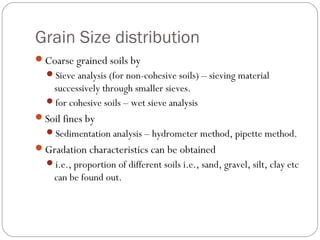
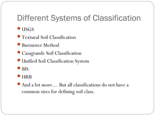
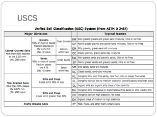
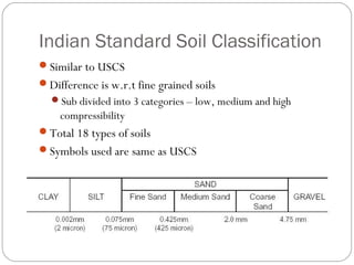
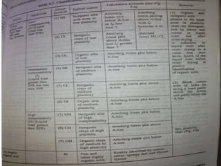
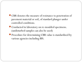
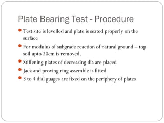
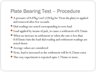
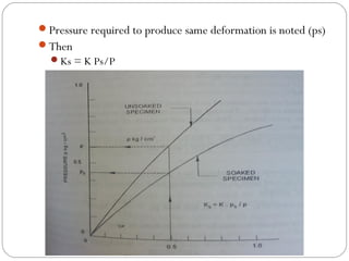
www.justbtech.com
PAVEMENT MATERIALS
Introduction
Pavement subjected to various conditions
Weather changes
Impact loads
Imposed loads etc.
Should not undergo excessive deformation and settlement
Differential settlement – failure of pavement
Hence, high compressibility and plastic properties are not
desirable for pavement construction
Good quality soil is required
Pavement Cross section
Consists of different layers
Embankment
Subgrade
Subbase
Base
Wearing course
Different types of materials are used depending on the layer
requirement.
Soil is the main constituent in Subgrade and embankment
Aggregates are used in the Sub base and base layer
Aggregates and binding material in the top layer
Sub grade and embankment provides support for the
pavement
Different types of failures such as rutting and shoving in the
flexible pavements, cracking in the rigid (concrete)
pavements are due to poor subgrade soil.
Soil
Accumulation or deposit of earth material formed by the
disintegration of rocks
Desirable Properties:
Stability
Incompressibility
Permanency of strength
Minimum change in volume
Good drainage
Ease of compaction
Index Properties of Soil
The soil properties based on which identification and
classification are done are known as index properties.
Grain Size Distribution
Liquid limit
Plasticity Index
Grain size distribution is determined by mechanical analysis
Liquid limit by Casagrande apparatus
Grain Size distribution
Coarse grained soils by
Sieve analysis (for non-cohesive soils) – sieving material
successively through smaller sieves.
for cohesive soils – wet sieve analysis
Soil fines by
Sedimentation analysis – hydrometer method, pipette method.
Gradation characteristics can be obtained
i.e., proportion of different soils i.e., sand, gravel, silt, clay etc
can be found out.
Grain Size Distribution Curves
Consistency Limits and Indices
•Atterberg limits are the limits of water content used to define
soil behavior.
Soil types
Based on the particle size and properties
Different types are there
Classification is primarily based upon
Grain Size distribution
Index Properties
Based on the grain size, soils are classified as below.
Gravel
Sand
Silt
Clay
Different Systems of Classification
USGS
Textural Soil Classification
Burmister Method
Casagrande Soil Classification
Unified Soil Classification System
BIS
HRB
And a lot more… But all classifications do not have a
common sizes for defining soil class.
Unified Soil Classification
Developed By Casagrande in 1948
Airfield construction - world war II
Modified to suit the reqt of other constructions
According to USCS
Coarse grained soils –> (grain size distribution): More than
50% retained on 75micron
Fine grained soils –> (plasticity characteristics): More than
50% passes through 75micron
USC System
Gravel – More than 50% on sieve no: 4 (4.75mm)
Sand - More than 50% passes sieve no: 4 (4.75mm)
Coarse grained contains <5% fines – well graded (GW, SW)
Poorly graded – GP, SP
For more than 12% fines – GM, GC, SM etc.
For Fine grained soils
LL is 50% or less – ML, SL etc (soils of low compressibility)
MH, SH etc., - LL more than 50% ( soils of high
compressibility)
Highly organic soils are termed as peat
USCS
Indian Standard Soil Classification
Similar to USCS
Difference is w.r.t fine grained soils
Sub divided into 3 categories – low, medium and high
compressibility
Total 18 types of soils
Symbols used are same as USCS
Indian Standard Soil Classification
Tests on Soil
For evaluating the properties of soil
Strength, Stiffness etc are studied
Shear tests
Bearing Tests
Penetration tests
Shear Tests
Carried out on the small samples
Performed in the laboratory
Direct Shear tests
Tri-axial compression test
Un-confined compression test
Bearing Tests
Carried out on the subgrade soils
Insitu tests
Load bearing area
Results vary with the properties of the soil under the test
Penetration test is a small scale bearing test
Size of loaded area is small
Ratio of penetration to size of loaded area is large
Can be insitu or laboratory
California Bearing Ratio Test (CBR)
Developed by the California Division of Highway
For classifying and evaluating the Soil sub grade and base
course materials for flexible pavements
It is an empirical test
Cannot be related directly with the fundamental properties of
the soil
Used to determine material properties for pavement design
CBR denotes the measure of resistance to penetration of
pavement material or soil, of standard plunger under
controlled conditions.
Conducted in laboratory on re-moulded specimens.
(undisturbed samples can also be used)
Procedure for determining CBR value is standardized by
various agencies including BIS.
Plunger of 50mm
1.25mm/minute penetration
Load reqd. for penetration of 2.5mm and 5.0mm are
recorded.
CBR value is expressed as the percentage of the standard
load value in standard material.
For 2.5mm penetration
Standard load = 1370kg, unit standard load = 70kg/cm2
For 5.0mm penetration
Standard load = 2055mm, unit standard load = 105kg/cm2
CBR Test
Specimen in mould is compacted to maximum dry density
(OMM)
IS heavy compaction as per IS: 2720 part VII for heavy traffic
roads
IS light compaction for low traffic roads
The specimen subjected to soaking for 4 days
Swelling and water absorption are noted
Then weight is placed on the top of specimen in the mould.
Assembly is placed under the plunger of the loading frame.
Reasons for Initial Concavity of shape
Top layer of the soaked soil is too soft after soaking
Top surface of soil not even
Plunger is not vertical
Plunger arrangement is wrong
Normally penetration value at 2.5mm is higher than 5.0mm.
And higher value is recorded as CBR.
Average of 3 test specimens have to taken as the value.
Presence of coarse grained particles result in poor
reproducibility of results
Material passing through 20mm sieve is only used in the test.
PLATE BEARING TEST
Plate Bearing Test – Apparatus
Bearing Plates – 750, 600, 450 and 300mm dia and 15 to
25mm thickness
A loading device consisting of hydraulic jack and proving ring
arrangement or pressure gauge
Reaction frame for giving thrust to plates.
Datum frame and dial gauges are used to measure settlement
of loaded plate.
Plate Bearing Test - Procedure
Test site is levelled and plate is seated properly on the
surface
For modulus of subgrade reaction of natural ground – top
soil upto 20cm is removed.
Stiffening plates of decreasing dia are placed
Jack and proving ring assemble is fitted
3 to 4 dial guages are fixed on the periphery of plates
Plate Bearing Test – Procedure
A pressure of 0.07kg/cm2 (320 kg for 75cm dia plate) is applied
and removed after few seconds
Dial readings are noted corresponding to zero load
Load applied by means of jack, to cause a settlement of 0.25mm
When no increase in settlement or when the rate is less than
0.025mm/min the load dial reading and settlement readings are
noted down
Average values are considered
Next, load is increased so the settlement will be 0.25mm extra
This way experiment is repeated upto 1.75mm or more.
Modulus of subgrade reaction is the reaction pressure
sustained by the soil sample under a rigid plate of standard
diameter per unit settlement measured at a specified
pressure or settlement.
IRC specifies that the K value be measured at 1.25 mm
settlement.
K = p/0.125 (kg/cm2/cm)
Allowance for Worst Subgrade Moisture
K value will be lowest at soaked condition
Moisture content during test may seldom represent worst
condition at site
K value obtained is modified by a factor to represent the
worst condition
2 consolidation test specimens are prepared
1 sample tested in un-soaked condition in lab – pressure –
deformation curve drawn (pressure for 0.125mm is noted)
2nd
specimen soaked
Pressure required to produce same deformation is noted (ps)
Then
Ks = K Ps/P
Correction for smaller plate
Some cases not possible to cause settlement of 0.175cm for
the 75 dia plate
Smaller dia plate will be used
Obtained K1 value is modified
Assuming subgrade as an elastic medium, where modulus of
elasticity is
∆ = 1.18pa/E
But , K = p/ ∆ = E/1.18a
If E is constant for a soil, Ka = K1a1 => K = K1a1/a
Aggregates
Objectives
Role of aggregates
Source of aggregates
Properties of aggregates
Tests on aggregates
Introduction
Combination or group of particle masses
Used with binding medium
92-96 percent of bituminous concrete
70 -80 percent of cement concrete
Sources
Natural
Obtained from large rock formation by quarrying
Excavated rock is crushed to obtain aggregates of different sizes
Manufactured
By product of industries
Brick ballast
Classification on Natural Aggregates
Igneous
Cooling of magma
Crystalline in structure
Grain size classification, composition based classification
Sedimentary
Formed by various deposits
Classified based on predominant mineral
Metamorphic
Formed from igneous or sedimentary
Desirable properties
Clean and free of clay and organic matter
Be angular and not flaky
Desirable properties
Clean and free from clay and organic matter
Strength
Hardness
Toughness
Shape
Adhesion with bitumen
Durability
Be non- absorptive
Be resistant to abrasion on exposure to traffic
Freedom from deleterious particles
Chemical Properties of aggregates
Important for bituminous and cement concrete mixes
Surface chemistry decides how well bitumen adheres to
aggregate
Poor adhesion results in stripping causing the failure of
pavements
In PCC pavements, if reactive silica is present in aggregates it
reacts expansively with cement paste. Causing expansion,
which leads to cracking and other types of failures.
Stripping of aggregates
One of the main failure modes in bituminous pavements
Due to loss of adhesion
Water affinity ( hydrophilic or hydrophobic)
Alkali-aggregate reaction
This is main mode of failure
Chemical reaction between aggregates and hydroxyl ions a
associated alkalis in the cement
Concrete deterioration is slow but progressive
Depending on the type of minerals present in the minerals
these reactions and resultant decay varies
Physical properties of aggregates
Gradation and size
Toughness and abrasion resistance
Durability and soundness
Particle shape and surface texture
Specific gravity
cleanliness
Gradation and Size
Effect of gradation and size in bituminous mixes
Workability
Layer thickness
Thickness of lift
Stability
Stiffness
Resistance to deformation
Fatigue strength
durability
Permeability
Surface texture and frictional resistance
Physical properties – gradation and
size
Effect of gradation and size in bituminous mixes
Strength
Dimensions of structural element
w/c ratio
Stability
Durability
Workability
Fatigue strength
shrinkage
Strength, Hardness, Toughness
Subjected to
Stress action due to wheel load
Wear and tear
Crushing
Hardness
Constant rubbing and abrasion
Hard enough to resist the abrasive action caused by traffic
Toughness
Resistance to impact
Ex: jumping of steel wheels
Shape, Adhesion, Durability
Rounded, cubical, angular, flaky or elongated shape
Flaky and elongated particles will have less strength
Should have less affinity with water
Other wise stripping will occur
Withstand adverse weather action
Also called as soundness
Should be clean and free from organic matter
Aggregate tests
Crushing test
Abrasion test
Impact test
Soundness test
Shape test
Specific gravity and water absorption test
Bitumen adhesion test
Crushing Test
Testing aggregate against compressive stress
IS:2386 Part – IV
Provides a relative measure of resistance to crushing
Specimen in the mould is subjected to gradual load
Dry aggregates passing through 12.5mm sieve and retained
on 10mm sieve
Filled in cylindrical mould of 11.5 mm dia and 18cm heigh
3 layers tampered each 25 times
Crushing Test
Test sample is weighed (w1) and placed in cylinder
Compressive load of 40 tonnes applied at a rate of 4 tonnes
per minute
Crushed aggregates are sieved through 2.36mm sieve
Weight of material passing the sieve is measured (w2)
Aggregate crushing value = (w1/w2)x100
< 10 indicates strong aggregate
Above 35 means weak
Abrasion test
To test the hardness property of aggregates
Los Angeles abrasion test is used
Standardized by BIS, IS:2386 Part IV
Principle is to find the percentage wear due to relative
rubbing action between aggregate and steel balls
Consists of a steel drum (dia 700mm, length 520mm)
Abrasive charge – steel balls of dia 48mm and weight 350 to
450 gms are placed inside the cylinder
No of spheres to be used depends on the grading of sample
Abrasion test
Quantity depends on gradation ( 5 to 10kg)
Cylinder rotated at around 33-35 rpm for 500 to 1000
rotations
Material is sieved through 1.7mm sieve
Passed amount is expressed as percentage of total aggregate
weight
This is called los angeles abrasion value. Max values are,
For WBM – 40
Bituminous concrete - 35
Impact test
Resistance to impact of aggregates
Aggregates passing 12.5 mm sieve and retained on 10 mm sieve
Filled in a cylindrical steel cup of internal dia 10.2 mm and depth
5 cm
Material filled in 3 layers
Metal hammer of weight 13.5 to 14 kgs is arranged to drop with a
free fall of 38cm in vertical direction
Total blows are 15
Crushed aggregate is passed through 2.36mm IS sieve
Aggregate Impact value = Expressed as ratio of total weight
Max value for: WBM is 40, Bituminous concrete is 35
Soundness test
To evaluate resistance to weathering action
Accelerated weathering test cycles
Aggregates of specified size are subjected to cycles of
alternate wetting in a saturated solution of either sodium
sulphate or magnesium sulphate for 16 - 18 hours and then
dried in oven at 105 − 110C.
5 cycles
Loss in weight is determined by sieving
Loss in weight should not exceed 12 percent when tested
with sodium sulphate and 18% when tested with magnesium
sulphate solution.
Shape tests
The particle shape of the aggregate mass is determined by the
percentage of flaky and elongated particles in it.
The flakiness index is defined as the percentage by weight of
aggregate particles whose least dimension is less than 0.6 times
their mean size.
The elongation index of an aggregate is defined as the
percentage by weight of particles whose greatest dimension
(length) is 1.8 times their mean dimension. (applicable only to
aggregates larger than 6.3mm)
Specific gravity and water absorption
Specific gravity of an aggregate is considered to be a measure
of strength or quality of the material
Absorption properties also indicate the strength. More
porous rocks are weak in nature.
Test Procedure:
2 kg sample of aggregate is washed and drained, kept in wire
basket.
Immersed in distilled water at temperature 22 to 32 C with
water cover atleast 50mm.
Trapped air is removed by dropping the basket for 25 times
at a height of 25mm from the bottom.
And weight of basket and aggregates is noted in immersed
condition. (W1).
Then they are removed from water and allowed to drain for few
minutes.
Aggregates kept in a dry water absorbent cloth
Empty basket moved back to water, jolted 25 times, weight is
W2.
Then aggregates moved to another dry cloth and again dried for
10 to 60 minutes.
Weight of surface dried aggregate = W3
Aggregate kept in oven at 110 C for 24 hours.
Cooled and weighed. (W4)
Bitumen adhesion test
Bitumen adheres well to all normal types of road aggregates
provided they are dry and free from dust
Adhesion problem occurs when the aggregate is wet and cold
the presence of water causes stripping of binder from the
coated aggregates
Static immersion test
The principle of the test is by immersing aggregate fully
coated with binder in water maintained at 400C temperature
for 24 hours.
IRC has specified maximum stripping value of aggregates
should not exceed 5%.
Thank You
Visit www.justbtech.com for more

Pavement materials in Road Construction

  • 1.
  • 2.
    Introduction Pavement subjected tovarious conditions Weather changes Impact loads Imposed loads etc. Should not undergo excessive deformation and settlement Differential settlement – failure of pavement Hence, high compressibility and plastic properties are not desirable for pavement construction Good quality soil is required
  • 3.
    Pavement Cross section Consistsof different layers Embankment Subgrade Subbase Base Wearing course Different types of materials are used depending on the layer requirement.
  • 4.
    Soil is themain constituent in Subgrade and embankment Aggregates are used in the Sub base and base layer Aggregates and binding material in the top layer Sub grade and embankment provides support for the pavement Different types of failures such as rutting and shoving in the flexible pavements, cracking in the rigid (concrete) pavements are due to poor subgrade soil.
  • 5.
    Soil Accumulation or depositof earth material formed by the disintegration of rocks Desirable Properties: Stability Incompressibility Permanency of strength Minimum change in volume Good drainage Ease of compaction
  • 6.
    Index Properties ofSoil The soil properties based on which identification and classification are done are known as index properties. Grain Size Distribution Liquid limit Plasticity Index Grain size distribution is determined by mechanical analysis Liquid limit by Casagrande apparatus
  • 7.
    Grain Size distribution Coarsegrained soils by Sieve analysis (for non-cohesive soils) – sieving material successively through smaller sieves. for cohesive soils – wet sieve analysis Soil fines by Sedimentation analysis – hydrometer method, pipette method. Gradation characteristics can be obtained i.e., proportion of different soils i.e., sand, gravel, silt, clay etc can be found out.
  • 8.
  • 9.
    Consistency Limits andIndices •Atterberg limits are the limits of water content used to define soil behavior.
  • 10.
    Soil types Based onthe particle size and properties Different types are there Classification is primarily based upon Grain Size distribution Index Properties Based on the grain size, soils are classified as below. Gravel Sand Silt Clay
  • 11.
    Different Systems ofClassification USGS Textural Soil Classification Burmister Method Casagrande Soil Classification Unified Soil Classification System BIS HRB And a lot more… But all classifications do not have a common sizes for defining soil class.
  • 12.
    Unified Soil Classification DevelopedBy Casagrande in 1948 Airfield construction - world war II Modified to suit the reqt of other constructions According to USCS Coarse grained soils –> (grain size distribution): More than 50% retained on 75micron Fine grained soils –> (plasticity characteristics): More than 50% passes through 75micron
  • 13.
    USC System Gravel –More than 50% on sieve no: 4 (4.75mm) Sand - More than 50% passes sieve no: 4 (4.75mm) Coarse grained contains <5% fines – well graded (GW, SW) Poorly graded – GP, SP For more than 12% fines – GM, GC, SM etc. For Fine grained soils LL is 50% or less – ML, SL etc (soils of low compressibility) MH, SH etc., - LL more than 50% ( soils of high compressibility) Highly organic soils are termed as peat
  • 14.
  • 15.
    Indian Standard SoilClassification Similar to USCS Difference is w.r.t fine grained soils Sub divided into 3 categories – low, medium and high compressibility Total 18 types of soils Symbols used are same as USCS
  • 16.
    Indian Standard SoilClassification
  • 18.
    Tests on Soil Forevaluating the properties of soil Strength, Stiffness etc are studied Shear tests Bearing Tests Penetration tests
  • 19.
    Shear Tests Carried outon the small samples Performed in the laboratory Direct Shear tests Tri-axial compression test Un-confined compression test
  • 20.
    Bearing Tests Carried outon the subgrade soils Insitu tests Load bearing area Results vary with the properties of the soil under the test Penetration test is a small scale bearing test Size of loaded area is small Ratio of penetration to size of loaded area is large Can be insitu or laboratory
  • 21.
    California Bearing RatioTest (CBR) Developed by the California Division of Highway For classifying and evaluating the Soil sub grade and base course materials for flexible pavements It is an empirical test Cannot be related directly with the fundamental properties of the soil Used to determine material properties for pavement design
  • 22.
    CBR denotes themeasure of resistance to penetration of pavement material or soil, of standard plunger under controlled conditions. Conducted in laboratory on re-moulded specimens. (undisturbed samples can also be used) Procedure for determining CBR value is standardized by various agencies including BIS.
  • 24.
    Plunger of 50mm 1.25mm/minutepenetration Load reqd. for penetration of 2.5mm and 5.0mm are recorded. CBR value is expressed as the percentage of the standard load value in standard material. For 2.5mm penetration Standard load = 1370kg, unit standard load = 70kg/cm2 For 5.0mm penetration Standard load = 2055mm, unit standard load = 105kg/cm2
  • 25.
    CBR Test Specimen inmould is compacted to maximum dry density (OMM) IS heavy compaction as per IS: 2720 part VII for heavy traffic roads IS light compaction for low traffic roads The specimen subjected to soaking for 4 days Swelling and water absorption are noted Then weight is placed on the top of specimen in the mould. Assembly is placed under the plunger of the loading frame.
  • 27.
    Reasons for InitialConcavity of shape Top layer of the soaked soil is too soft after soaking Top surface of soil not even Plunger is not vertical Plunger arrangement is wrong Normally penetration value at 2.5mm is higher than 5.0mm. And higher value is recorded as CBR. Average of 3 test specimens have to taken as the value. Presence of coarse grained particles result in poor reproducibility of results Material passing through 20mm sieve is only used in the test.
  • 28.
  • 29.
    Plate Bearing Test– Apparatus Bearing Plates – 750, 600, 450 and 300mm dia and 15 to 25mm thickness A loading device consisting of hydraulic jack and proving ring arrangement or pressure gauge Reaction frame for giving thrust to plates. Datum frame and dial gauges are used to measure settlement of loaded plate.
  • 30.
    Plate Bearing Test- Procedure Test site is levelled and plate is seated properly on the surface For modulus of subgrade reaction of natural ground – top soil upto 20cm is removed. Stiffening plates of decreasing dia are placed Jack and proving ring assemble is fitted 3 to 4 dial guages are fixed on the periphery of plates
  • 31.
    Plate Bearing Test– Procedure A pressure of 0.07kg/cm2 (320 kg for 75cm dia plate) is applied and removed after few seconds Dial readings are noted corresponding to zero load Load applied by means of jack, to cause a settlement of 0.25mm When no increase in settlement or when the rate is less than 0.025mm/min the load dial reading and settlement readings are noted down Average values are considered Next, load is increased so the settlement will be 0.25mm extra This way experiment is repeated upto 1.75mm or more.
  • 33.
    Modulus of subgradereaction is the reaction pressure sustained by the soil sample under a rigid plate of standard diameter per unit settlement measured at a specified pressure or settlement. IRC specifies that the K value be measured at 1.25 mm settlement. K = p/0.125 (kg/cm2/cm)
  • 34.
    Allowance for WorstSubgrade Moisture K value will be lowest at soaked condition Moisture content during test may seldom represent worst condition at site K value obtained is modified by a factor to represent the worst condition 2 consolidation test specimens are prepared 1 sample tested in un-soaked condition in lab – pressure – deformation curve drawn (pressure for 0.125mm is noted) 2nd specimen soaked
  • 35.
    Pressure required toproduce same deformation is noted (ps) Then Ks = K Ps/P
  • 36.
    Correction for smallerplate Some cases not possible to cause settlement of 0.175cm for the 75 dia plate Smaller dia plate will be used Obtained K1 value is modified Assuming subgrade as an elastic medium, where modulus of elasticity is ∆ = 1.18pa/E But , K = p/ ∆ = E/1.18a If E is constant for a soil, Ka = K1a1 => K = K1a1/a
  • 37.
    Aggregates Objectives Role of aggregates Sourceof aggregates Properties of aggregates Tests on aggregates
  • 38.
    Introduction Combination or groupof particle masses Used with binding medium 92-96 percent of bituminous concrete 70 -80 percent of cement concrete
  • 39.
    Sources Natural Obtained from largerock formation by quarrying Excavated rock is crushed to obtain aggregates of different sizes Manufactured By product of industries Brick ballast
  • 40.
    Classification on NaturalAggregates Igneous Cooling of magma Crystalline in structure Grain size classification, composition based classification Sedimentary Formed by various deposits Classified based on predominant mineral Metamorphic Formed from igneous or sedimentary
  • 41.
    Desirable properties Clean andfree of clay and organic matter Be angular and not flaky
  • 42.
    Desirable properties Clean andfree from clay and organic matter Strength Hardness Toughness Shape Adhesion with bitumen Durability Be non- absorptive Be resistant to abrasion on exposure to traffic Freedom from deleterious particles
  • 43.
    Chemical Properties ofaggregates Important for bituminous and cement concrete mixes Surface chemistry decides how well bitumen adheres to aggregate Poor adhesion results in stripping causing the failure of pavements In PCC pavements, if reactive silica is present in aggregates it reacts expansively with cement paste. Causing expansion, which leads to cracking and other types of failures.
  • 44.
    Stripping of aggregates Oneof the main failure modes in bituminous pavements Due to loss of adhesion Water affinity ( hydrophilic or hydrophobic)
  • 45.
    Alkali-aggregate reaction This ismain mode of failure Chemical reaction between aggregates and hydroxyl ions a associated alkalis in the cement Concrete deterioration is slow but progressive Depending on the type of minerals present in the minerals these reactions and resultant decay varies
  • 46.
    Physical properties ofaggregates Gradation and size Toughness and abrasion resistance Durability and soundness Particle shape and surface texture Specific gravity cleanliness
  • 47.
    Gradation and Size Effectof gradation and size in bituminous mixes Workability Layer thickness Thickness of lift Stability Stiffness Resistance to deformation Fatigue strength durability Permeability Surface texture and frictional resistance
  • 48.
    Physical properties –gradation and size Effect of gradation and size in bituminous mixes Strength Dimensions of structural element w/c ratio Stability Durability Workability Fatigue strength shrinkage
  • 49.
    Strength, Hardness, Toughness Subjectedto Stress action due to wheel load Wear and tear Crushing Hardness Constant rubbing and abrasion Hard enough to resist the abrasive action caused by traffic Toughness Resistance to impact Ex: jumping of steel wheels
  • 50.
    Shape, Adhesion, Durability Rounded,cubical, angular, flaky or elongated shape Flaky and elongated particles will have less strength Should have less affinity with water Other wise stripping will occur Withstand adverse weather action Also called as soundness Should be clean and free from organic matter
  • 51.
    Aggregate tests Crushing test Abrasiontest Impact test Soundness test Shape test Specific gravity and water absorption test Bitumen adhesion test
  • 52.
    Crushing Test Testing aggregateagainst compressive stress IS:2386 Part – IV Provides a relative measure of resistance to crushing Specimen in the mould is subjected to gradual load Dry aggregates passing through 12.5mm sieve and retained on 10mm sieve Filled in cylindrical mould of 11.5 mm dia and 18cm heigh 3 layers tampered each 25 times
  • 53.
    Crushing Test Test sampleis weighed (w1) and placed in cylinder Compressive load of 40 tonnes applied at a rate of 4 tonnes per minute Crushed aggregates are sieved through 2.36mm sieve Weight of material passing the sieve is measured (w2) Aggregate crushing value = (w1/w2)x100 < 10 indicates strong aggregate Above 35 means weak
  • 54.
    Abrasion test To testthe hardness property of aggregates Los Angeles abrasion test is used Standardized by BIS, IS:2386 Part IV Principle is to find the percentage wear due to relative rubbing action between aggregate and steel balls Consists of a steel drum (dia 700mm, length 520mm) Abrasive charge – steel balls of dia 48mm and weight 350 to 450 gms are placed inside the cylinder No of spheres to be used depends on the grading of sample
  • 55.
    Abrasion test Quantity dependson gradation ( 5 to 10kg) Cylinder rotated at around 33-35 rpm for 500 to 1000 rotations Material is sieved through 1.7mm sieve Passed amount is expressed as percentage of total aggregate weight This is called los angeles abrasion value. Max values are, For WBM – 40 Bituminous concrete - 35
  • 56.
    Impact test Resistance toimpact of aggregates Aggregates passing 12.5 mm sieve and retained on 10 mm sieve Filled in a cylindrical steel cup of internal dia 10.2 mm and depth 5 cm Material filled in 3 layers Metal hammer of weight 13.5 to 14 kgs is arranged to drop with a free fall of 38cm in vertical direction Total blows are 15 Crushed aggregate is passed through 2.36mm IS sieve Aggregate Impact value = Expressed as ratio of total weight Max value for: WBM is 40, Bituminous concrete is 35
  • 57.
    Soundness test To evaluateresistance to weathering action Accelerated weathering test cycles Aggregates of specified size are subjected to cycles of alternate wetting in a saturated solution of either sodium sulphate or magnesium sulphate for 16 - 18 hours and then dried in oven at 105 − 110C. 5 cycles Loss in weight is determined by sieving Loss in weight should not exceed 12 percent when tested with sodium sulphate and 18% when tested with magnesium sulphate solution.
  • 58.
    Shape tests The particleshape of the aggregate mass is determined by the percentage of flaky and elongated particles in it. The flakiness index is defined as the percentage by weight of aggregate particles whose least dimension is less than 0.6 times their mean size. The elongation index of an aggregate is defined as the percentage by weight of particles whose greatest dimension (length) is 1.8 times their mean dimension. (applicable only to aggregates larger than 6.3mm)
  • 59.
    Specific gravity andwater absorption Specific gravity of an aggregate is considered to be a measure of strength or quality of the material Absorption properties also indicate the strength. More porous rocks are weak in nature. Test Procedure: 2 kg sample of aggregate is washed and drained, kept in wire basket. Immersed in distilled water at temperature 22 to 32 C with water cover atleast 50mm. Trapped air is removed by dropping the basket for 25 times at a height of 25mm from the bottom.
  • 60.
    And weight ofbasket and aggregates is noted in immersed condition. (W1). Then they are removed from water and allowed to drain for few minutes. Aggregates kept in a dry water absorbent cloth Empty basket moved back to water, jolted 25 times, weight is W2. Then aggregates moved to another dry cloth and again dried for 10 to 60 minutes. Weight of surface dried aggregate = W3 Aggregate kept in oven at 110 C for 24 hours. Cooled and weighed. (W4)
  • 63.
    Bitumen adhesion test Bitumenadheres well to all normal types of road aggregates provided they are dry and free from dust Adhesion problem occurs when the aggregate is wet and cold the presence of water causes stripping of binder from the coated aggregates Static immersion test The principle of the test is by immersing aggregate fully coated with binder in water maintained at 400C temperature for 24 hours. IRC has specified maximum stripping value of aggregates should not exceed 5%.
  • 64.