Downloaded 128 times


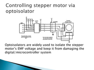
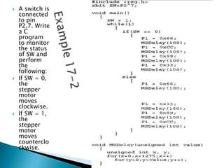


Here is a C program to control a stepper motor based on the status of a switch connected to P2.7: #include <reg51.h> sbit switch = P2^7; void main() { while(1) { if(switch==0) { // if switch is off clockwise(); // move motor clockwise } else { // if switch is on counterclockwise(); // move motor counterclockwise } } } void clockwise() { // code to energize motor coils in sequence for clockwise rotation } void counterclockwise() { // code to energize motor coils in