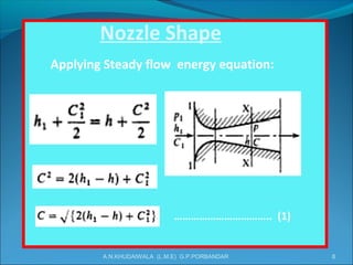
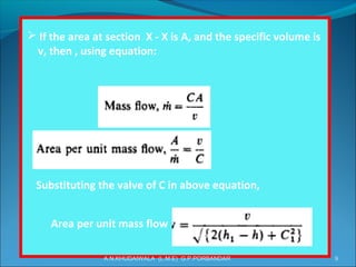
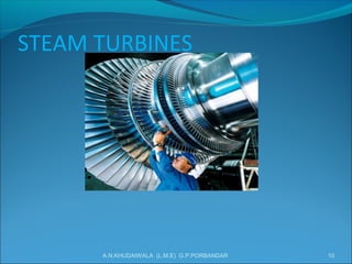
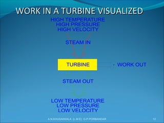
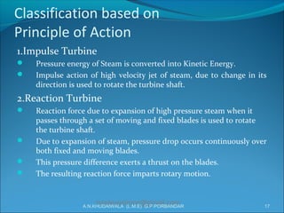
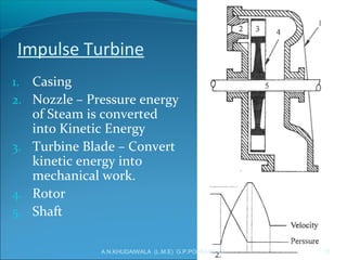
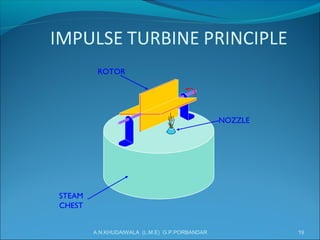
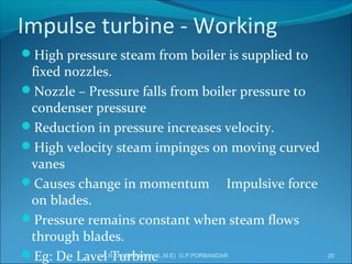
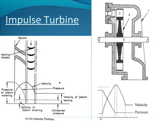
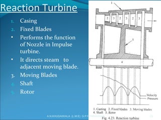
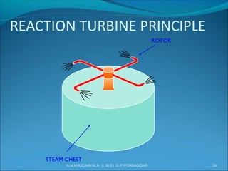
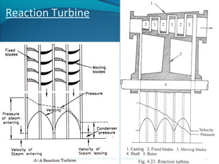
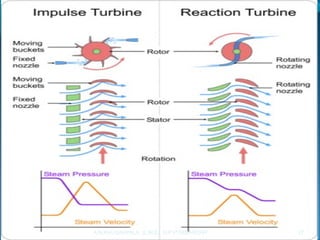
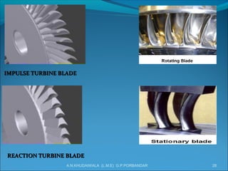
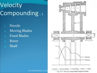
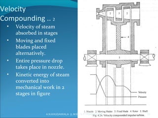
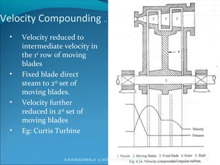
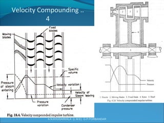
Prime movers are devices that convert energy into mechanical work. The document discusses two main types of prime movers - steam engines and steam turbines. It provides details on the components, working, and types of steam turbines, including impulse and reaction turbines. The key components of steam turbines are nozzles, blades (fixed and moving), rotors, and shafts. Steam turbines work by converting the pressure energy of steam into kinetic energy and then into rotational mechanical energy to power the turbine shaft.
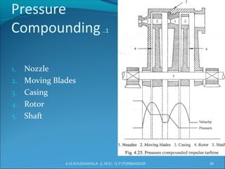

![[PPT] on Steam Turbine](https://cdn.slidesharecdn.com/ss_thumbnails/spsharmafinalppt-140608082156-phpapp01-thumbnail.jpg?width=640&height=640&fit=bounds)


