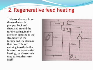
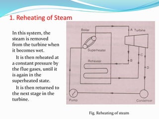
This document discusses methods to improve the efficiency of steam turbines, including reheating steam, regenerative feed heating, and binary vapor plants. Reheating steam involves removing steam from the turbine when it becomes wet, reheating it to a superheated state, and returning it to the next turbine stage. This increases work output, efficiency, and reduces blade erosion and water consumption. Regenerative feed heating involves using steam bled from the turbine to preheat feedwater entering the boiler, improving efficiency. Binary vapor plants use a lower boiling point fluid like mercury as the working fluid, allowing higher turbine inlet temperatures and thus greater efficiencies than steam turbines alone.

![Reheat Cycle
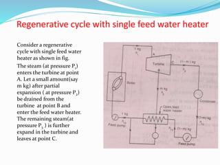
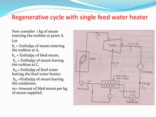
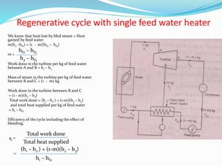
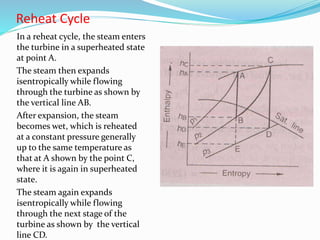
Now consider a steam turbine with
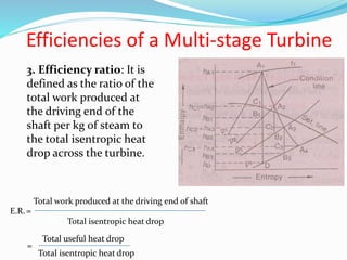
a reheating system as shown in Fig.
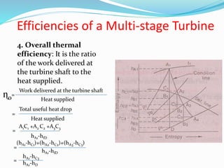
Let, hA = Enthalpy of steam at A,
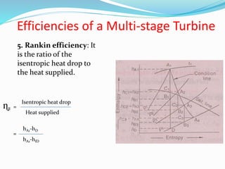
hB, hC, hD = Corresponding values at
B,C and D,
hfD = Enthalpy of water at D.
Total heat supplied = Total heat at
A +Heat supplied between B and C
= hA +[(hC -hB )– hfD ]
Work done = Total heat drop
= (hA - hB) + (hC - hD)
and efficiency ɳ =
=
Total heat supplied
Work done
(hA - hB) + (hC - hD)
hA +[(hC -hB )– hfD ]](https://image.slidesharecdn.com/9thlecturemodernturbine-180118094258/85/modern-steam-turbine-7-320.jpg)