A steam turbine is a prime mover in which the potential energy of the steam is transformed into kinetic energy and later in its turn is transformed into the mechanical energy of rotation of the turbine shaft
A steam turbine is a prime mover in which the potential energy of the steam is transformed into kinetic energy and later in its turn is transformed into the mechanical energy of rotation of the turbine shaft
Governing of the Turbine | Fluid MechanicsSatish Taji
Watch Video of this presentation on Link: https://youtu.be/LmJtNo-zgjo
For notes/articles, Visit my blog (link is given below).
For Video, Visit our YouTube Channel (link is given below).
Any Suggestions/doubts/reactions, please leave in the comment box.
Follow Us on
YouTube: https://www.youtube.com/channel/UCVPftVoKZoIxVH_gh09bMkw/
Blog: https://e-gyaankosh.blogspot.com/
Facebook: https://www.facebook.com/egyaankosh/
INTRODUCTION
THERMODYNAMIC CYCLE OF STEAM FLOW
RANKINE CYCLE (IDEAL , ACTUAL ,REHEAT)
LAYOUT OF STEAM POWER PLANT
MAJOR COMPONENTS AND THEIR FUNCTIONS
ALTERNATOR
EXCITATION SYSTEM
GOVERNING SYSTEM
Simple description about gas turbine. Where you are going to know about its classification,advantages and disadvantages also.Here also you can find-out where it is actually usages.
Sachpazis:Terzaghi Bearing Capacity Estimation in simple terms with Calculati...Dr.Costas Sachpazis
Terzaghi's soil bearing capacity theory, developed by Karl Terzaghi, is a fundamental principle in geotechnical engineering used to determine the bearing capacity of shallow foundations. This theory provides a method to calculate the ultimate bearing capacity of soil, which is the maximum load per unit area that the soil can support without undergoing shear failure. The Calculation HTML Code included.
Final project report on grocery store management system..pdfKamal Acharya
In today’s fast-changing business environment, it’s extremely important to be able to respond to client needs in the most effective and timely manner. If your customers wish to see your business online and have instant access to your products or services.
Online Grocery Store is an e-commerce website, which retails various grocery products. This project allows viewing various products available enables registered users to purchase desired products instantly using Paytm, UPI payment processor (Instant Pay) and also can place order by using Cash on Delivery (Pay Later) option. This project provides an easy access to Administrators and Managers to view orders placed using Pay Later and Instant Pay options.
In order to develop an e-commerce website, a number of Technologies must be studied and understood. These include multi-tiered architecture, server and client-side scripting techniques, implementation technologies, programming language (such as PHP, HTML, CSS, JavaScript) and MySQL relational databases. This is a project with the objective to develop a basic website where a consumer is provided with a shopping cart website and also to know about the technologies used to develop such a website.
This document will discuss each of the underlying technologies to create and implement an e- commerce website.
Vaccine management system project report documentation..pdfKamal Acharya
The Division of Vaccine and Immunization is facing increasing difficulty monitoring vaccines and other commodities distribution once they have been distributed from the national stores. With the introduction of new vaccines, more challenges have been anticipated with this additions posing serious threat to the already over strained vaccine supply chain system in Kenya.
Event Management System Vb Net Project Report.pdfKamal Acharya
In present era, the scopes of information technology growing with a very fast .We do not see any are untouched from this industry. The scope of information technology has become wider includes: Business and industry. Household Business, Communication, Education, Entertainment, Science, Medicine, Engineering, Distance Learning, Weather Forecasting. Carrier Searching and so on.
My project named “Event Management System” is software that store and maintained all events coordinated in college. It also helpful to print related reports. My project will help to record the events coordinated by faculties with their Name, Event subject, date & details in an efficient & effective ways.
In my system we have to make a system by which a user can record all events coordinated by a particular faculty. In our proposed system some more featured are added which differs it from the existing system such as security.
Cosmetic shop management system project report.pdfKamal Acharya
Buying new cosmetic products is difficult. It can even be scary for those who have sensitive skin and are prone to skin trouble. The information needed to alleviate this problem is on the back of each product, but it's thought to interpret those ingredient lists unless you have a background in chemistry.
Instead of buying and hoping for the best, we can use data science to help us predict which products may be good fits for us. It includes various function programs to do the above mentioned tasks.
Data file handling has been effectively used in the program.
The automated cosmetic shop management system should deal with the automation of general workflow and administration process of the shop. The main processes of the system focus on customer's request where the system is able to search the most appropriate products and deliver it to the customers. It should help the employees to quickly identify the list of cosmetic product that have reached the minimum quantity and also keep a track of expired date for each cosmetic product. It should help the employees to find the rack number in which the product is placed.It is also Faster and more efficient way.
Welcome to WIPAC Monthly the magazine brought to you by the LinkedIn Group Water Industry Process Automation & Control.
In this month's edition, along with this month's industry news to celebrate the 13 years since the group was created we have articles including
A case study of the used of Advanced Process Control at the Wastewater Treatment works at Lleida in Spain
A look back on an article on smart wastewater networks in order to see how the industry has measured up in the interim around the adoption of Digital Transformation in the Water Industry.
Student information management system project report ii.pdfKamal Acharya
Our project explains about the student management. This project mainly explains the various actions related to student details. This project shows some ease in adding, editing and deleting the student details. It also provides a less time consuming process for viewing, adding, editing and deleting the marks of the students.
Democratizing Fuzzing at Scale by Abhishek Aryaabh.arya
Presented at NUS: Fuzzing and Software Security Summer School 2024
This keynote talks about the democratization of fuzzing at scale, highlighting the collaboration between open source communities, academia, and industry to advance the field of fuzzing. It delves into the history of fuzzing, the development of scalable fuzzing platforms, and the empowerment of community-driven research. The talk will further discuss recent advancements leveraging AI/ML and offer insights into the future evolution of the fuzzing landscape.
NO1 Uk best vashikaran specialist in delhi vashikaran baba near me online vas...Amil Baba Dawood bangali
Contact with Dawood Bhai Just call on +92322-6382012 and we'll help you. We'll solve all your problems within 12 to 24 hours and with 101% guarantee and with astrology systematic. If you want to take any personal or professional advice then also you can call us on +92322-6382012 , ONLINE LOVE PROBLEM & Other all types of Daily Life Problem's.Then CALL or WHATSAPP us on +92322-6382012 and Get all these problems solutions here by Amil Baba DAWOOD BANGALI
#vashikaranspecialist #astrologer #palmistry #amliyaat #taweez #manpasandshadi #horoscope #spiritual #lovelife #lovespell #marriagespell#aamilbabainpakistan #amilbabainkarachi #powerfullblackmagicspell #kalajadumantarspecialist #realamilbaba #AmilbabainPakistan #astrologerincanada #astrologerindubai #lovespellsmaster #kalajaduspecialist #lovespellsthatwork #aamilbabainlahore#blackmagicformarriage #aamilbaba #kalajadu #kalailam #taweez #wazifaexpert #jadumantar #vashikaranspecialist #astrologer #palmistry #amliyaat #taweez #manpasandshadi #horoscope #spiritual #lovelife #lovespell #marriagespell#aamilbabainpakistan #amilbabainkarachi #powerfullblackmagicspell #kalajadumantarspecialist #realamilbaba #AmilbabainPakistan #astrologerincanada #astrologerindubai #lovespellsmaster #kalajaduspecialist #lovespellsthatwork #aamilbabainlahore #blackmagicforlove #blackmagicformarriage #aamilbaba #kalajadu #kalailam #taweez #wazifaexpert #jadumantar #vashikaranspecialist #astrologer #palmistry #amliyaat #taweez #manpasandshadi #horoscope #spiritual #lovelife #lovespell #marriagespell#aamilbabainpakistan #amilbabainkarachi #powerfullblackmagicspell #kalajadumantarspecialist #realamilbaba #AmilbabainPakistan #astrologerincanada #astrologerindubai #lovespellsmaster #kalajaduspecialist #lovespellsthatwork #aamilbabainlahore #Amilbabainuk #amilbabainspain #amilbabaindubai #Amilbabainnorway #amilbabainkrachi #amilbabainlahore #amilbabaingujranwalan #amilbabainislamabad
Automobile Management System Project Report.pdfKamal Acharya
The proposed project is developed to manage the automobile in the automobile dealer company. The main module in this project is login, automobile management, customer management, sales, complaints and reports. The first module is the login. The automobile showroom owner should login to the project for usage. The username and password are verified and if it is correct, next form opens. If the username and password are not correct, it shows the error message.
When a customer search for a automobile, if the automobile is available, they will be taken to a page that shows the details of the automobile including automobile name, automobile ID, quantity, price etc. “Automobile Management System” is useful for maintaining automobiles, customers effectively and hence helps for establishing good relation between customer and automobile organization. It contains various customized modules for effectively maintaining automobiles and stock information accurately and safely.
When the automobile is sold to the customer, stock will be reduced automatically. When a new purchase is made, stock will be increased automatically. While selecting automobiles for sale, the proposed software will automatically check for total number of available stock of that particular item, if the total stock of that particular item is less than 5, software will notify the user to purchase the particular item.
Also when the user tries to sale items which are not in stock, the system will prompt the user that the stock is not enough. Customers of this system can search for a automobile; can purchase a automobile easily by selecting fast. On the other hand the stock of automobiles can be maintained perfectly by the automobile shop manager overcoming the drawbacks of existing system.
Overview of the fundamental roles in Hydropower generation and the components involved in wider Electrical Engineering.
This paper presents the design and construction of hydroelectric dams from the hydrologist’s survey of the valley before construction, all aspects and involved disciplines, fluid dynamics, structural engineering, generation and mains frequency regulation to the very transmission of power through the network in the United Kingdom.
Author: Robbie Edward Sayers
Collaborators and co editors: Charlie Sims and Connor Healey.
(C) 2024 Robbie E. Sayers
2. Some historical facts
• The first „turbine” was made by Hero
of Alexandria in the second century.
• In the end of XVIII century the
Industrial Revolution began
(in 1770 first reciprocating piston steam
engine invented by Thomas Newcomen
and invented by James Watt started its
work)
• The first steam turbines were
constructed in 1883 by Dr Gustaf de
Laval and in 1884 by sir Charles
Parsons
• In1896 Charles Curtis received a patent
on impulse turbine
• In 1910 was created radial turbine
(Ljungström)
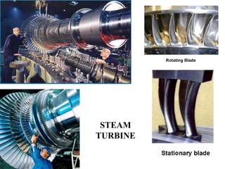
3. Steam Turbine
• Steam turbine convert a part of the energy of the steam
evidenced by high temperature and pressure into
mechanical power-in turn electrical power
• The steam from the boiler is expanded in a nozzle,
resulting in the emission of a high velocity jet. This jet of
steam impinges on the moving vanes or blades, mounted
on a shaft. Here it undergoes a change of direction of
motion which gives rise to a change in momentum and
therefore a force.
• The motive power in a steam turbine is obtained by the
rate of change in momentum of a high velocity jet of
steam impinging on a curved blade which is free to rotate.
The conversion of energy in the blades takes place
by impulse, reaction or impulse reaction principle.
4. PRINCIPLE OF OPERATION OF STEAM TURBINE
• The steam turbine depends completely upon
the dynamic action of the steam.
• According to Newton’s second law of
motion, the force is proportional to the rate
of change of momentum (mass x velocity).
If the rate of change of momentum is caused
in the steam by allowing a high velocity jet
steam to pass over curved blade, the steam
will impart a force to the blade. If the blade
is free, it will move off (rotate) in the
direction of force.
• In fig.8.1(a)
C1 = Initial velocity,
C2 = Final velocity
5. PRINCIPLE OF OPERATION
1. A nozzle in which heat energy of high pressure steam is converted into
kinetic energy so that steam issues from the nozzle with very high velocity.
2. Blades which change the direction of steam issuing from the nozzle so that a
force acts on blades due to change of momentum and rotates them.
So, the basic principle of operation a steam turbine is generation of
high velocity steam jet by expansion of high pressure steam in a nozzle and
motive power in the turbine is obtained by change in momentum of the
high velocity steam jet by allowing it to impinge on curved blades.
Steam turbines are steady flow machines, have large exhaust outlets (for
discharging used steam) and the speed of flow is very high. So, they can
handle large volume of steam and produce higher power and the processes
are assumed to be adiabatic. Steam turbines are capable of expanding steam
to the lowest exhaust pressure obtainable in the condenser. The turbine is a
constant high speed machine and really must be operated condensing in
order to take full advantage of greater range of steam expansion.
7. ABC / Mechanical Science /
Chapter 10 / TP 10 - 7 / Rev 02
WORK IN A TURBINE VISUALIZED
Fig 10-1
8. Steam Turbine Classification
Steam turbines can be classified in several different ways:
1. By details of stage design
• Impulse or reaction.
2. By steam supply and exhaust conditions
• Condensing, or Non-condensing (back pressure),
• Automatic or controlled extraction,
• Mixed pressure
• Reheat
3. By casing or shaft arrangement
• Single casing, Tandem compound or Cross compound
4. By number of exhaust stages in parallel:
• Two flow, Four flow or Six flow.
5. By direction of steam flow:
• Axial flow, Radial flow or Tangential flow
6. Single or multi-stage
7. By steam supply
9. CLASSIFICATION
• Based on action of steam
Impulse
Reaction
Combination of impulse and reaction
• Based on number of pressure stages
Single stage
Multi stage Impulse and Reaction turbines
Based on Direction of steam flow
Axial turbines
Radial turbines
Based on no of cylinders
Single
Double
Three cylinder
Four cylinder
10. CLASSIFICATION
• Based on action of steam
Impulse
Reaction
Combination of impulse and reaction
• Based on number of pressure stages
Single stage
Multi stage Impulse and Reaction turbines
Based on Direction of steam flow
Axial turbines
Radial turbines
Based on no of cylinders
Single
Double
Three cylinder
Four cylinder
13. The Impulse Principle
• It is impossible to have 1800 curved blade in actual application
– jet exit will impinging on the back of next blade
• Blade entrance angle and blade exit angle cannot be zero, as
shown in the figure below
15. TYPES OF IMPULSE TURBINE
• Simple Impulse Turbine.
• Compounding of Impulse Turbine.
16. Impulse Turbine
• The basic idea of an impulse turbine is that a jet of
stream from a fixed nozzle pushes against the rotor
blades and impels them forward.
• The velocity of steam is twice as fast as the velocity
of blade.
• Pressure drops take place in the fixed blade (nozzle).
• Blade is usually symmetrical.
• Entrance angle (φ ) and exit angle (γ) are around 20o.
• Usually used in the entrance high-pressure stages of
a steam turbine.
• Enthalpy drop and pressure drop occur in the nozzle.
17.
18. SIMPLE IMPULSE TURBINE
• It is the impulse turbine, where the steam
expanded within the nozzle and there is no any
change in the steam pressure as it passes over the
blades.
• It means that the pressure remain constant
through turbine.
• Single stage impulse turbine is called as
De laval Turbine
20. DE-LAVEL TURBINE
A De-lavel turbine named after Swedish Engineer De-lavel is the
simplest impulse turbine and is commonly used.
The essential parts of an impulse turbine are - nozzles, blades and casing.
21. Impulse turbine
• In Impulse turbine, the enthalpy drop (pressure drop) completely
occurs in the nozzle itself and when the fluid pass over the moving
blades it will not suffer pressure drop again.
• Hence pressure remain constant when the fluid pass over the rotor
blades. Fig. shows the schematic diagram of Impulse turbine.
25. COMPOUNDING OF IMPULSE TURBINE
• Compounding is a method for reducing the rotational speed of
the impulse turbine to practical limits.
• If the high velocity of stream is allowed to flow through one row
of moving blades, it produces a rotor speed of about
30,000 r.p.m. which is too high for practical use.
• Leaving loss is also very high. It is therefore essential to
incorporate some improvement in the simple impulse turbine for
possible by making use also to achieve high performance.
• This is possible by making use of more than one set of nozzles,
blades, rotors, in a series keyed to a common shaft, so that either
the steam pressure or the jet velocity is absorbed by the turbine in
stages.The leaving loss also will than be less.
This process is called compounding of steam turbine.
26. WHY COMPOUNDING IS REQUIRED?
• The steam produced in the boiler has got very
high enthalpy. In all turbines the blade velocity is
directly proportional to the velocity of the steam
passing over the blade.
• Now, if the entire energy of the steam is extracted
in one stage, i.e. if the steam is expanded from the
boiler pressure to the condenser pressure in a
single stage, then its velocity will be very high.
Hence the velocity of the rotor (to which the
blades are keyed) can reach to about 30,000 rpm,
which is pretty high for practical uses.
• Moreover at such high speeds the centrifugal
forces are immense, which can damage the
structure. Hence, compounding is needed.
27. TYPE OF COMPOUNDED IMPULSE TURBINE
• Pressure Compounded Impulse Turbine
• Velocity Compounded Impulse Turbine
• Pressure and Velocity Compounded Impulse Turbine
• WHAT IS COMPOUMDING?
• Compounding is employed for reducing the rotational speed of
the impulse turbine to practical limits.
• Compounding of steam turbines is the method in which energy
from the steam is extracted in a number of stages rather than a
single stage in a turbine.
• A compounded steam turbine has multiple stages i.e. it has
more than one set of nozzles and rotors, in series, keyed to the
shaft or fixed to the casing, so that either the steam pressure or
the jet velocity is absorbed by the turbine in number of stages.
14 April 2022 5th Semester (Mechanical) 27
28. PRESSURE COMPOUNDED IMPULSE TURBINE
• In this type of turbine, the compounding is done for pressure of steam only
i.e. to reduce the high rotational speed of turbine the whole expansion of
steam is arranged in a number of steps by employing a number of simple
turbine in a series keyed on the same shaft.
• Each of these simple impulse turbine consisting of one set of nozzles and
row of moving blades is known as a stage of the turbine and thus this turbine
consists of several stages.
• The exhaust from each row of moving blades enters the succeeding set of
nozzles.
• Thus we can say that this arrangement is nothing but splitting up the whole
pressure drop from the steam chest pressure to the condenser pressure into
a series of smaller pressure drop across several stages of impulse turbine and
hence this turbine is called Pressure – compound impulse turbine
• THIS IS ALSO KNOWN AS RATEAU TURBINE.
33. VELOCITY COMPOUNDED IMPULSE TURBINE
• In this type of turbine, the compounding is done for velocity of
steam only i.e. drop in velocity is arranged in many small drops
through many moving row of blades instead of a single row of
moving blades.
• In this turbine, moving and fixed blades ( guide blades ) are
placed alternately.
• Moving blades are fitted with the wheel while the fixed blades
are fitted with the casing.
• The whole expansion of steam from the steam chest pressure
down to the exhaust pressure take place in the nozzles only.
• Therefore pressure remain constant after nozzle. IT IS ALSO
KNOWN AS CURTIS TURBINE.
14 April 2022 5th Semester (Mechanical) 33
38. PRESSURE-VELOCITY COMPOUNDED IMPULSE TURBINE
• Here we consider pressure and velocity simultaneously,
hence it is named as pressure velocity compounded
impulse turbine.
• Here we have arrangement of two rotars or wheels.in
each rotars we have installation of many row of moving
blades,hence we get a decrease in velocity.
• Also we install two nozzles in whole arrangement, which
helps in splitting pressure.
• Here we use two row wheels as we consider two row
wheels arrangement more efficient than three row
wheels arrangement.
14 April 2022 5th Semester (Mechanical) 38
39. P-V COMPOUNDED IMPULSE TURBINE
14 April 2022 5th Semester (Mechanical) 39
Movin
g blade
Nozzl
e
Guide
blade
44. Velocity Triangles
• The three velocity vectors namely, blade speed,
absolute velocity and relative velocity in relation
to the rotor are used to form a triangle called
velocity triangle.
• Velocity triangles are used to illustrate the flow
in the bladings of turbo machinery.
• Changes in the flow direction and velocity are
easy to understand
• with the help of the velocity triangles.
• Note that the velocity triangles are drawn for the
inlet and outlet of the rotor at certain radii.
45.
46.
47.
48.
49. Analysis on single stage turbine:
General velocity diagram of Impulse turbine:
If there is no frictional loss, then the axial thrust is zero as
Vf1 = Vf2 and Vr1 = Vr2
51. Due to the effect of blade friction loss, the relative velocity at outlet
is reduced than the relative velocity at inlet. Therefore
Vr2 = Cb Vr1. Corresponding velocity triangle shown if fig (b)
54. Notation
Let
Vb = Linear velocity of moving blade.
V1 = Absolute velocity of steam at inlet to moving blade i.e., exit velocity
of nozzle.
Vw1 = Tangential component of entering steam. Vw1 Also known
as velocity ofwhirl at entrance.
Vr1 = Relative velocity of steam with respect to tip of blade at
inlet. It is the vectorial difference between Vb and V1
Vf1 =Velocity of flow = Axial velocity at entrance to moving
blades. It is the vertical component of V1
α1 = Angle of nozzle = Angle which the entering steam makes with the
moving blade at entrance - with the tangent of the wheel at
entrance.
β1 = Angle which the relative velocity makes with the tangent of the wheel
direction of motion of blade. It is also known as blade angle at inlet.
The above notations stand for inlet triangle.
V2, Vw2, Vf2, Vr2, α2, β2 are the corresponding values at the exit of the
moving blades. They
stand for outlet triangle.
55. Working
The steam jet with absolute velocity V1 impinges on the blade at an angle of α1 to
the tangent of the blade. The absolute velocity V2 can be considered as having two
components. The tangential component called whirl component Vw1 = V1cosα1 is
parallel to direction of rotation of blade sand axial or flow component Vf1 = Vsin α1
is perpendicular to the direction of rotation of blades.
The tangential component of the steam jet does work on the blade because it is in the
same direction as the motion of the blade. The axial component doesn't work on the
blades because it is perpendicular to the direction of motion of blade. It is responsible
for the flow of steam through the turbine. Change of velocity in this component
causes an axial thrust on the rotor.
As the blade moves with a tangential velocity in peripheral direction, the entering
steam jet will have relative velocity to the blades. If there is no friction loss at the
blade, relative velocity at inlet is equal to relative velocity at outlet i.e., Vr1= Vr2.
As the steam glides over the blades without shock, the surface of the blade at inlet
must be parallel to relative velocity Vr1. So, the moving blade at inlet must be
inclined to the tangent of the blade at an angle β1. In other words, to avoid shock at
entrance, vector Vr1 must betangential to the blade tip at entry i.e, β1 must be equal
to angle of blade at entrance. The blade is designed on this principle.
56. From the above analysis, following points are to be noted.
1. No expansion of steam takes place in the moving blades. The
blades only deflect steam. This causes change in momentum
and consequently force.
2. If the steam has to enter and leave the blades without shock,
angle β1, should be angle of blade at inlet and angle β2 should
be angle of blade at outlet. This is an essential condition.
3. Since there is no pressure drop in the moving blades, the
pressure on the two sides of the blades is equal.
4. α 1is the outlet angle of nozzle. If steam has to enter the next
nozzle ring without shock, its inlet angle must be equal to α2.
5. In a simple impulse turbine, the loss at exit is the whirl
component at outlet - V2 cos α2. For minimum loss, this
quantity should be minimum, i.e., α2 should be equal to 90°.
In that case the turbine discharges axially and it is called axial
turbine.
57. Construction of combined velocity diagram :
1. First, draw a horizontal line and cut off AB equal to velocity of blade to some
suitable scale.
2. From 5, draw a line BC at an angle a1, with AB. Cut off BC equal to V1 to scale.
3. Join AC. It represents Vr1.
4. From A; draw a line AD at an angle β2 with AB. With A as centre and radius
equal to AC, draw an arc that meets the line through A at D such that AC =
AD. Or Vr1 = Vr2.
5. Join BD. It represents absolute velocity at exit to scale.
6. From C and D draw perpendiculars to meet the line AB produced at E and F.
7. Now; to scale,
EB = velocity of whirl at entrance. BF = velocity of whirl at exit.
CE = velocity of flow at inlet. DF = velocity of flow at outlet.
When friction is neglected, there will be no fall in steam pressure as it flows over
the blades and Vr1 = Vr2.
Also, when friction is absent, β1 = β2 and Vf1 = Vf2
58.
59. EFFECT OF BLADE FRICTION
In an impulse turbine, the relative velocity remains same as steam
passes over the blades if friction is neglected.
In actual practice, the flow of steam the blades is resisted by
friction. The effect of this friction is to reduce the relative velocity
of steam while passing over the blades-
Generally, there is a loss of 10-15% in relative velocity. Owing
to friction in blades. Vr2 is less than Vr1 and we may write
The ratio of Vr2 to Vr1 is called blade velocity coefficient or
coefficient of velocity friction factor K. The effect of blade friction is
to reduce relative velocity at outlet and consequently Vw2 This in
turn will cause reduction in work done and blade efficiency.
Depending upon the shape of the blades, value of K varies from
0.75 to 0.85.
60. Forces On Blade And Work Done, Power Developed by Blade
• FORCES ON BLADE AND WORK DONE BY BLADE
• The work done may be found out from the change of momentum of steam
jet during its flow over the blades. As mentioned earlier, velocity of whirl is
responsible for work on the blade.
• 1. Force on Rotor:
• According to Newton's second law of motion,
• Tangential force on rotor = mass x tangential acceleration.
• m = Mass rate of steam flow - kgs/sec.
• Actually, Vw2 is negative as the steam is discharged in opposite direction to
blade motion. So, Vw1 and Vw2 are added together. Generally,
• Positive sign is to be used when Vw2 and Vb are in opposite direction as
shown above and negative sign is to be used when Vw2 and Vb are in same
direction.
61. Power Developed by the Turbine:
Power = Rate of doing work
(1 watt= 1 N-m/sec)
This power is known as Rim power or diagram power to
distinguish it from shaft power.
4. Axial Thrust on Rotor:
Axial force
Fa= Mass x Axial acceleration
= Mass x change in velocity of flow.
This axial force must be balanced or must be taken by a thrust
bearing.
62. Efficiencies of Turbine
Blade or Diagram Efficiency :
It is defined as the ratio of work done on blades to energy supplied
to blades. This is also called diagram efficiency
Let V1 = Absolute velocity of steam at inlet —m/sec
m = Mass of steam supplied — kgs/sec.
Energy of steam supplied to blade = 1/2*m*V1
2
Work done on blade = m . (Vw1 ± Vw2) . Vb J/sec
Diagram or blading efficiency
63. Gross or Stage Efficiency:
• stage consists of a set of nozzles and a row of moving blades
and so, stage efficiency includes the performance of nozzles
also.
• Stage efficiency is defined as the ratio of work done on blades
per kg of steam to total energy supplied per stage per kg of
steam.
• If h1 and h2 represent before and after expansion of steam
• through the nozzles, then the enthalpy drop (h1- h2) is the
enthalpy drop through a stage, i.e., the heat energy (h1 - h2) is
the energy supplied per stage per kg of steam.
64. Nozzle Efficiency
• It is defined as the ratio of energy supplied to blades per kg of
steam to total energy supplied per stage per kg of steam.
• Energy supplied to blades per kg of steam = 1/2*m*V1
2
• Total energy supplied per stage per kg of steam = (h1-h2)
• Stage efficiency = blade efficiency x nozzle efficiency.
• Energy converted to heat by blade friction= Loss of kinetic
energy during flow over the blades
65. Condition for Maximum Utilization Factor or Blade efficiency with Equiangular
Blades for Impulse Turbine:
66. Condition for maximum utilization factor or blade efficiency with
equiangular blades for Impulse turbine and the influence of blade
efficiency on the steam speed in a single stage Impulse turbine can be
obtained by considering corresponding velocity diagrams as shown in Fig.9.
Due to the effect of blade friction loss, the relative velocity at outlet is
reduced than the relative velocity at inlet. Therefore, Vr2 = CbVr1,
corresponding to this condition, velocity triangles (qualitative only) are
drawn as shown in figure.
67.
68.
69. Reaction Principle
• Fixed nozzle, a rocket, a whirling lawn sprinkle and turbine are
devices that cause a fluid to exit at high speeds.
• The fluid beginning with zero velocity inside, creates a force in
the direction of motion F equal to
• F = ma
73. Reaction Turbine
In this type of turbine, there is a gradual pressure drop and takes
place continuously over the fixed and moving blades. The rotation of the
shaft and drum, which carrying the blades is the result of both impulse and
reactive force in the steam. The reaction turbine consist of a row of
stationary blades and the following row of moving blades .
The fixed blades act as a nozzle which are attached inside the
cylinder and the moving blades are fixed with the rotor as shown in figure
When the steam expands over the blades there is gradual increase
in volume and decrease in pressure. But the velocity decrease in the
moving blades and increases in fixed blades with change of direction.
Because of the pressure drops in each stage, the number of stages
required in a reaction turbine is much greater than in a impulse turbine of
same capacity.
It also concluded that as the volume of steam increases at lower
pressures therefore the diameter of the turbine must increase after each
group of blade rings.
75. Reaction turbine.
`
• In Reaction turbines, addition to the pressure drop occurs in the
nozzle there will also be pressure drop occur when the fluid passes
over the rotor blades. Fig. shows the Reaction turbine.
• Most of the steam turbine are of axial flow type devices except
Ljungstrom turbine which is a radial type.
76. Reaction Turbine
• Reaction stage has pressure drop across the
moving blade.
• Not suitable for high pressure stage because
pressure drop is very high and results in steam
leakage around the tips of the blades.
• Impulse turbine is normally used for HP stages.
• Reaction turbine is normally used for LP stages.
77. Reaction Turbine
pressure
Absolute velocity
Nozzles with full steam admission
Unsymmetrical blade
Similar shape to fixed blade
(opposite direction curve)
Pressure continually drops through all rows of
blades (fixed and moving)
Absolute velocity changes within each stage
repeats from stage to stage
50 % Degree of reaction
-Half of enthalpy drop of the stage occurs at fixed
blade
-Half of enthalpy drop of the stage occurs at moving
blade
83. Forces acting on a reaction blade
Reaction force:
is due to the change in
momentum relative velocity of
the steam while passing over
the blade passage.
Centrifugal force:
is the force acting on the blade
due to change in radius of
steam entering and leaving
the turbine.
Resultant force:
is the resultant of Reaction
force and Centrifugal force.
www.bookspar.com | Website for Students
| VTU NOTES | QUESTION PAPERS
83
84. Reaction turbines:
These are of axial type. But pure reaction turbine are not in
general use, only impulse-reaction turbines are used.
1. The velocity triangle for general case:
In reaction turbine steam continuously expands as it flows
over the blades thereby increases the relative velocity of
steam, i.e., Vr2 > Vr1
85. Parson’s Turbine
• Parson’s turbine is a particular case of reaction
turbine in which the degree of reaction is half.
• The section of blades of this turbine is the same in
both fixed and moving rows of blades.
• In the parson’s turbine, the blade section and the
mean diameter of fixed as well as the moving blades
are the same.
• The blade height is progresively so increased such
that the velocity of steam at exit from each row of
blades is uniform throughout the stage.
86. Thus, the velocity triangle at the inlet and outlet of moving
blades will be similar.
• The parson’s turbine is designed for 50% reaction,then
the equation of degree of reaction can be written as
• R=1/2=Vf(cot --cot )/2Vb
therefore,Vb=Vf(cot -- cot )
• Also , Vb can be written as
Vb=Vf(cot -cot α)
Vb=Vf(cot α -cot β)
• Comparing the equations, α= and = β
Sub: CPE Topic: Parson’s Turbine and condition for maximum efficiency
of Parson’s Reaction turbine
87. Velocity diagram for Parson’s reaction
turbine
Sub: CPE Topic: Parson’s Turbine and condition for maximum
efficiency
88. Condition for maximum efficiency of
parson’s reaction turbine
Work done per kg of steam is given by
W=Vb(Vw1+Vw2)=Vb[V1cosα+(Vr2cos -Vb)
For parson’s turbine ,
=α and Vr2=V1
Therefore, W=Vb[2V1 cosα- Vb]
=V1
2[2VbV1 cosα/v1
2-Vb
2/V1
2]
= V1
2 [2 cosα-2]
Where, =Vb/V1
Sub: CPE Topic: Parson’s Turbine and condition for maximum efficiency
of Parson’s Reaction turbine
89. The kinetic energy supplied to the fixed blade=V1
2/2g
The kinetic energy supplied to the
moving blade= Vr2
2-Vr1
2/2
Therefore, Total energy supplied to the stage,
h=(V1
2/2)+(Vr2
2-Vr1
2/2)
For symmetrical tri-angels Vr2=V1
h= (V1
2/2)+(V1
2- Vr1
2/2 )= V1
2- Vr1
2/2
Sub: CPE Topic: Parson’s Turbine and condition for maximum
efficiency
of Parson’s Reaction turbine
90. Cosidering the ABD from velocity diagram
Vr1
2= V1
2+ Vb
2-2VbV1 cosα
h= V1
2-(V1
2+ Vb
2-2VbV1 cosα)/2
=(V1
2 +2VbV1 cosα-Vb
2)/2
= V1
2 /2[1+2Vbcosα/V1-(Vb/V1) 2 ]
h=V1
2 /2[1+2 cosα- 2 ]
Sub: CPE Topic: Parson’sTurbine and condition for maximum efficiency
of Parson’s Reaction turbine
91. • The blade efficiency of the reaction turbine is given
by
ƞ=Work done(W)/Total energy supplied( h)
=V1
2(2 cosα- 2 )/V1
2/2(1+2 cosα- 2)
=2(2 cosα- 2)/(1+2 cosα- 2)
=2 (2cosα- )/(1+2 cosα- 2)
=2(1+2 cosα- 2)-2/(1+2 cosα- 2)
=2-2/ 1+2 cosα- 2
Sub: CPE Topic: Parson’sTurbine and condition for maximum
efficiency
of Parson’s Reaction turbine
92. • The ƞb becomes maximum when factor 1+2 cosα- 2
becomes maximum,
• Therefore ,the required condition is
d/d (1+2 cosα- 2 )=0
therefore,2cosα-2 = 0
=cosα
i.e.The conditon for maximum efficiency, =Vb/V1
=cosα
Sub: CPE Topic: Parson’sTurbine and condition for maximum efficiency
of Parson’s Reaction turbine
93. • Substituting the value of in the equation,we get
(ƞb)max=2-2/1+2cosαcosα-cos2α
• therefore,
Maximum efficiency=
(ƞb)max=2cos2α /1+cos2α
Sub: CPE Topic: Parson’sTurbine and condition for maximum
efficiency
of Parson’s Reaction turbine
94. Degree of reaction
• Degree of reaction is a parameter that describes the relation
between the energy transfer due to the static pressure
change and the energy transfer due to dynamic pressure
change.
• The degree of reaction for reaction turbine stage is defined as
the ratio of enthalpy drop in the moving blades to the total
enthalpy drop in fixed and moving blades (i.e., static enthalpy
drop to total enthalpy drop), as shown in fig.
95.
96. The variation ηb with blade speed ratio Φ for the
reaction stage is shown in fig.
100. Difference between Impulse and Reaction Turbines
Sl no Particulars Impulse Turbine Reaction Turbine
1.
2.
3.
4.
5.
6.
7.
8.
9.
10.
Pressure drop
Area of blade
channels
Blades
Admission of
steam
Nozzles
Power
Space
Efficiency
Suitability
Blade
manufacture
Only in nozzles and not in
moving blades.
Constant.
Profile type.
Not all round.
Diaphragm contains the
nozzles.
Small power capacities.
Less space for same power.
Low
Small power requirements.
Easy
In fixed blades(nozzles) as well
as in moving blades.
Varying.
Aerofoil type.
All round.
Fixed blades attached to the
casing.
Much power can be
developed.
More space required.
High
For medium and high power
requirements.
Difficult
101. Steam turbine governing and control
Objective is to keep turbine speed fairly constant irrespective
of load . Different methods are
• Throttle governing
104. Comparison of Throttle and Nozzle
control Governing
Sl no. Particulars Throttle control Nozzle control
1.
2.
3.
4.
5.
Throttling losses
Partial admission
losses
Heat drop available
Use
Suitability
Severe
Low
Lesser
In both Impulse and
Reaction turbines.
Small turbines
Little losses
High
Larger
Mostly in Impulse turbine.
Medium and Large
turbines.
105. Effect of Reheat Factor and Stage Efficiency:
Consider a turbine with n number of stages, say n = 4
as shown in fig.