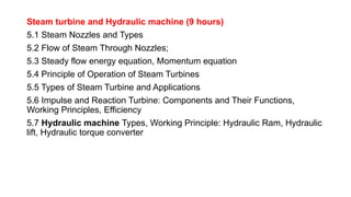
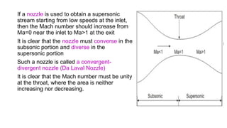
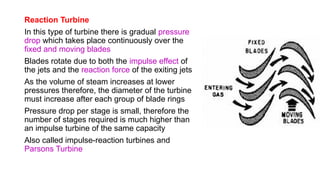
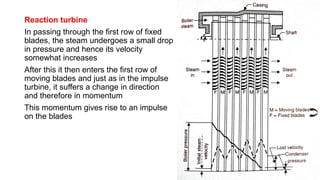
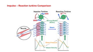
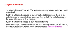
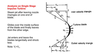
The document discusses steam turbines and hydraulic machines, outlining steam flow through nozzles, types of turbines (impulse and reaction), their operation principles, and applications. It details the functioning of steam power plants, including energy conversions and turbine classifications based on various parameters. Additionally, it covers hydraulic machines like hydraulic rams and lifts, emphasizing their working principles and efficiencies.

![Power Produced
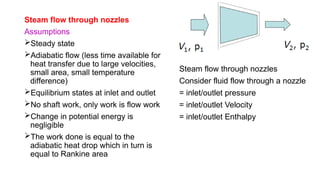
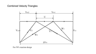
Mass of Steam flowing through Turbine =m kg/s
Change in velocity of whirl= (Vw1+Vw2)
Force in the direction of motion, Fx= m(Vw1+Vw2)
Work done in the direction of motion, Wx= m(Vw1+Vw2)u
Power produced by Turbine, P= m(Vw1+Vw2)u
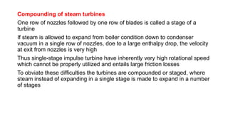
Axial thrust on the wheel, Fy=m(Vf1 - Vf2)
Efficiency = [m(Vw1+Vw2)u] / [0.5 mV1
2
] = [2(Vw1+Vw2)u] / V1
2](https://image.slidesharecdn.com/copyofchapter5-240811052315-ce61af6b/85/Steam-turbine-theory-based-on-fluid-machine-45-320.jpg)


![[PPT] on Steam Turbine](https://cdn.slidesharecdn.com/ss_thumbnails/spsharmafinalppt-140608082156-phpapp01-thumbnail.jpg?width=640&height=640&fit=bounds)


