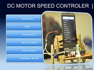
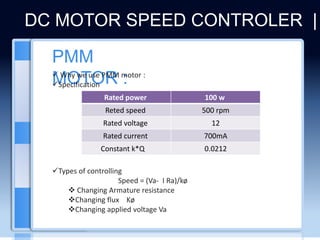
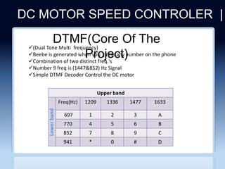
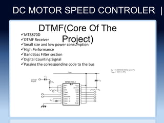
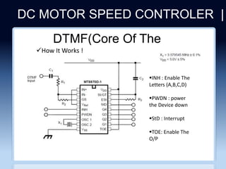
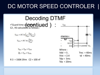
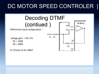
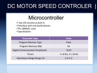
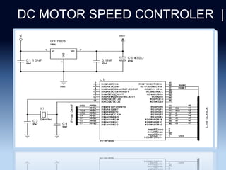
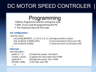
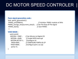
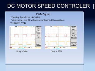
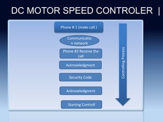
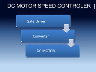
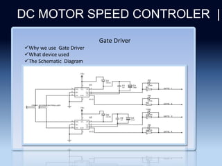
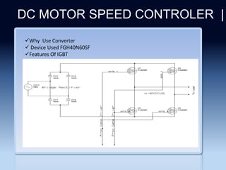
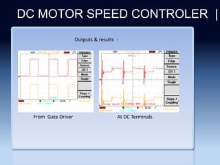
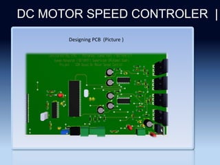
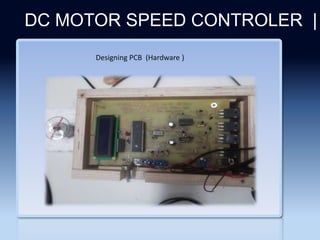
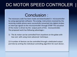
Section 2 DTMF
Power Circuit
Results & Video
Introduction
Future Outock
DC MOTOR SPEED CONTROLER |
Conclusion & Cost
DC MOTOR SPEED CONTROLER | In
Why we choose this project
Important of dc motor in industry
Dc motor used in many application
Dc motor :
 Types Of dc motor
:
DC MOTOR SPEED CONTROLER |
Shunt dc motor : Seried dc motor :
DC MOTOR SPEED CONTROLER |
Seperately excited
motor :
PMM motor :
DC MOTOR SPEED CONTROLER |
Seperately excited
motor :
PMM motor :
PMM
MOTOR :
 Why we use PMM motor :
Specification
Types of controlling
Speed = (Va- I Ra)/kø
 Changing Armature resistance
Changing flux Kø
Changing applied voltage Va
DC MOTOR SPEED CONTROLER |
100 w
Rated power
500 rpm
Reted speed
12
Rated voltage
700mA
Rated current
0.0212
Constant k*Q
DC MOTOR SPEED CONTROLER |
CLICHERE FOR MORE INFO
(Dual Tone Multi frequency)
Beebe is generated when you press any number on the phone
Combination of two distinct freq.'s
Number 9 freq is (1447&852) Hz Signal
Simple DTMF Decoder Control the DC motor
Upper band
1633
1477
1336
1209
Freq(Hz)
A
3
2
1
697
B
6
5
4
770
C
9
8
7
852
D
#
0
*
941
DTMF(Core Of The
Project)
Lower
band
DC MOTOR SPEED CONTROLER |
CLICHERE FOR MORE INFO
MT8870D
DTMF Receiver
Small size and low power consumption
High Performance
BandBass Filter section
Digital Counting Signal
Passing the corresponding code to the bus
DTMF(Core Of The
Project)
DC MOTOR SPEED CONTROLER |
CLICHERE FOR MORE INFO
DTMF(Core Of The
Project)
How It Works !
INH : Enable The
Letters (A,B,C,D)
PWDN : power
the Device down
StD : Interrupt
TOE: Enable The
O/P
DC MOTOR SPEED CONTROLER |
CLICHERE FOR MORE INFO
Decoding DTMF
(contiued ) :
Guard time adjustment :
C2 , R3 calculated as follows :
Where :
Vdd = 5 . Trec = 40ms
Vtst = 2.4 td = 40ms
Tdp = 5ms
Tda = 20ms
R 3 = 330K Ohm C2 = 100 nf
DC MOTOR SPEED CONTROLER |
Differential input configuration :
voltage gain = R2 / R1
R1 = 100K
R2 = 200K
C1 Chosen to be 100nf
Decoding DTMF
(contiued )
DC MOTOR SPEED CONTROLER |
CLICHERE FOR MORE INFO
 Has I/O circuitry as built in
Interface with real world devices
Pic 18f4620 used
Specification
Value
Parameter type
Flash
Program Memory Type
64
Program Memory (KB)
2CCP
Digital Communication Peripherals
1 x 8-bit, 3 x 16-bit
Timers
2 to 5.5
Operating Voltage Range (V)
Microcontroller
DC MOTOR SPEED CONTROLER |
CLICHERE FOR MORE INFO
DC MOTOR SPEED CONTROLER |
CLICHERE FOR MORE INFO
Programming
void interrupt() {
portb.f 2 = 1 ; // Enable the output from dtmf
number = portb ; // register the nalue taken from DTMF
portb.f2=0 ; //Disaple the output from DTMF
INTCON = 0x90; // Set T0IE, clear T0IF
}}
void lcd_con() {
Lcd_Config (&PORTD , 1, 3, 0, 4, 5, 6, 7) ; //configure portd as output
LCD_Cmd(LCD_CURSOR_OFF); // send command to LCD (cursor off)
LCD_Cmd(LCD_CLEAR); // send command to LCD (clear LCD)
}
Mikroc Programme Used for writing the code
JDM circuit used for programming the PIC
 The Important Parts Of The Code
DC MOTOR SPEED CONTROLER |
CLICHERE FOR MORE INFO
void main(){
ADCON1 = 0X0F ; // Set AN pins to Digital I/O
INTCON = 0x90; // Enable INT0 interrupt
INTCON.INT1IE=1 ; //configure int
TRISb=0Xf9 ; // CONFIGURE PORTb AS i/P
TRISA=0X00 ; //configure port a as o/p
porta= 0 ;
}
Void pwm2_generation() {
PWM2_Init(500kHz); // Initialize PWM1 module at 5KHz
PWM2_Change_Duty(current_duty2) ; // Set The Duty Of The Signal
PWM2_Start(); // start PWM1
}
Section 2
DC MOTOR SPEED CONTROLER |
PWM Signal
Setting Duty from (0-100)%
determines the DC voltage according To this equation :
V = (Duty) * Vdc
Duty = 50% Duty = 75%
Section 2
DC MOTOR SPEED CONTROLER |
Phone # 1 (make call )
Communicatio
n network
Acknowledgment
Phone #2 Receive the
call
Security Code
Acknowledgment
Starting Controll
Controlling
Process
DC MOTOR SPEED CONTROLER |
CLICHERE FOR MORE INFO
Gate Driver
Converter
DC MOTOR
Section 2
DC MOTOR SPEED CONTROLER |
Gate Driver
Why we use Gate Driver
What device used
The Schematic Diagram
Section 2
DC MOTOR SPEED CONTROLER |
Bootstrap capacitor sizing :
Section 2
DC MOTOR SPEED CONTROLER |
I/P And Output
input pwm with 50%duty output Signal With 50%duty
And 15 Voltage
Section 2
DC MOTOR SPEED CONTROLER |
Why Use Converter
 Device Used FGH40N60SF
Features Of IGBT
Section 2
DC MOTOR SPEED CONTROLER |
Outputs & results :
From Gate Driver At DC Terminals
Section 2
DC MOTOR SPEED CONTROLER |
Designing PCB (Picture )
Section 2
DC MOTOR SPEED CONTROLER |
Designing PCB (Hardware )
Section 2
DC MOTOR SPEED CONTROLER |
Video
Section 2
DC MOTOR SPEED CONTROLER |
FutureOut lock:
 improve the project in order to use it for driving large dc motors
 Improve the project to control and monitor the device in house
 Improving the programming
Section 2
DC MOTOR SPEED CONTROLER |
Conclusion :
The necessary code has been made and downloaded in microcontroller
by using appropriate software. The analog instructions received by the
receiving mobile phone were successfully converted into digital strobes
as interrupt signals to the microcontroller through DTMF The actuation
of the motor is driven by the output ports of the microcontroller.
The proposed work has following advantages :
1) The dc motor can be controlled from anywhere on the globe with
low cost with using more advanced technique .
2) A number of devices can be controlled through a dedicated output
port bits by writing the individual controlling algorithm for each device .
Section 2
DC MOTOR SPEED CONTROLER |
Cost (NIS)
40
Microcontroller
30
Ir2110
140
IGBT’S
60
PCB
70
BOX
10
DC MOTOR
70
LCD
100
OTHERS
TOTAL = 600 NIS
Section 2
DC MOTOR SPEED CONTROLER |
Section 2
DC MOTOR SPEED CONTROLER |

presentation_28 (1).pptx

  • 2.
    Section 2 DTMF PowerCircuit Results & Video Introduction Future Outock DC MOTOR SPEED CONTROLER | Conclusion & Cost
  • 3.
    DC MOTOR SPEEDCONTROLER | In Why we choose this project Important of dc motor in industry Dc motor used in many application
  • 4.
    Dc motor : Types Of dc motor : DC MOTOR SPEED CONTROLER | Shunt dc motor : Seried dc motor :
  • 5.
    DC MOTOR SPEEDCONTROLER | Seperately excited motor : PMM motor :
  • 6.
    DC MOTOR SPEEDCONTROLER | Seperately excited motor : PMM motor :
  • 7.
    PMM MOTOR :  Whywe use PMM motor : Specification Types of controlling Speed = (Va- I Ra)/kø  Changing Armature resistance Changing flux Kø Changing applied voltage Va DC MOTOR SPEED CONTROLER | 100 w Rated power 500 rpm Reted speed 12 Rated voltage 700mA Rated current 0.0212 Constant k*Q
  • 8.
    DC MOTOR SPEEDCONTROLER | CLICHERE FOR MORE INFO (Dual Tone Multi frequency) Beebe is generated when you press any number on the phone Combination of two distinct freq.'s Number 9 freq is (1447&852) Hz Signal Simple DTMF Decoder Control the DC motor Upper band 1633 1477 1336 1209 Freq(Hz) A 3 2 1 697 B 6 5 4 770 C 9 8 7 852 D # 0 * 941 DTMF(Core Of The Project) Lower band
  • 9.
    DC MOTOR SPEEDCONTROLER | CLICHERE FOR MORE INFO MT8870D DTMF Receiver Small size and low power consumption High Performance BandBass Filter section Digital Counting Signal Passing the corresponding code to the bus DTMF(Core Of The Project)
  • 10.
    DC MOTOR SPEEDCONTROLER | CLICHERE FOR MORE INFO DTMF(Core Of The Project) How It Works ! INH : Enable The Letters (A,B,C,D) PWDN : power the Device down StD : Interrupt TOE: Enable The O/P
  • 11.
    DC MOTOR SPEEDCONTROLER | CLICHERE FOR MORE INFO Decoding DTMF (contiued ) : Guard time adjustment : C2 , R3 calculated as follows : Where : Vdd = 5 . Trec = 40ms Vtst = 2.4 td = 40ms Tdp = 5ms Tda = 20ms R 3 = 330K Ohm C2 = 100 nf
  • 12.
    DC MOTOR SPEEDCONTROLER | Differential input configuration : voltage gain = R2 / R1 R1 = 100K R2 = 200K C1 Chosen to be 100nf Decoding DTMF (contiued )
  • 13.
    DC MOTOR SPEEDCONTROLER | CLICHERE FOR MORE INFO  Has I/O circuitry as built in Interface with real world devices Pic 18f4620 used Specification Value Parameter type Flash Program Memory Type 64 Program Memory (KB) 2CCP Digital Communication Peripherals 1 x 8-bit, 3 x 16-bit Timers 2 to 5.5 Operating Voltage Range (V) Microcontroller
  • 14.
    DC MOTOR SPEEDCONTROLER | CLICHERE FOR MORE INFO
  • 15.
    DC MOTOR SPEEDCONTROLER | CLICHERE FOR MORE INFO Programming void interrupt() { portb.f 2 = 1 ; // Enable the output from dtmf number = portb ; // register the nalue taken from DTMF portb.f2=0 ; //Disaple the output from DTMF INTCON = 0x90; // Set T0IE, clear T0IF }} void lcd_con() { Lcd_Config (&PORTD , 1, 3, 0, 4, 5, 6, 7) ; //configure portd as output LCD_Cmd(LCD_CURSOR_OFF); // send command to LCD (cursor off) LCD_Cmd(LCD_CLEAR); // send command to LCD (clear LCD) } Mikroc Programme Used for writing the code JDM circuit used for programming the PIC  The Important Parts Of The Code
  • 16.
    DC MOTOR SPEEDCONTROLER | CLICHERE FOR MORE INFO void main(){ ADCON1 = 0X0F ; // Set AN pins to Digital I/O INTCON = 0x90; // Enable INT0 interrupt INTCON.INT1IE=1 ; //configure int TRISb=0Xf9 ; // CONFIGURE PORTb AS i/P TRISA=0X00 ; //configure port a as o/p porta= 0 ; } Void pwm2_generation() { PWM2_Init(500kHz); // Initialize PWM1 module at 5KHz PWM2_Change_Duty(current_duty2) ; // Set The Duty Of The Signal PWM2_Start(); // start PWM1 }
  • 17.
    Section 2 DC MOTORSPEED CONTROLER | PWM Signal Setting Duty from (0-100)% determines the DC voltage according To this equation : V = (Duty) * Vdc Duty = 50% Duty = 75%
  • 18.
    Section 2 DC MOTORSPEED CONTROLER | Phone # 1 (make call ) Communicatio n network Acknowledgment Phone #2 Receive the call Security Code Acknowledgment Starting Controll Controlling Process
  • 19.
    DC MOTOR SPEEDCONTROLER | CLICHERE FOR MORE INFO Gate Driver Converter DC MOTOR
  • 20.
    Section 2 DC MOTORSPEED CONTROLER | Gate Driver Why we use Gate Driver What device used The Schematic Diagram
  • 21.
    Section 2 DC MOTORSPEED CONTROLER | Bootstrap capacitor sizing :
  • 22.
    Section 2 DC MOTORSPEED CONTROLER | I/P And Output input pwm with 50%duty output Signal With 50%duty And 15 Voltage
  • 23.
    Section 2 DC MOTORSPEED CONTROLER | Why Use Converter  Device Used FGH40N60SF Features Of IGBT
  • 24.
    Section 2 DC MOTORSPEED CONTROLER | Outputs & results : From Gate Driver At DC Terminals
  • 25.
    Section 2 DC MOTORSPEED CONTROLER | Designing PCB (Picture )
  • 26.
    Section 2 DC MOTORSPEED CONTROLER | Designing PCB (Hardware )
  • 27.
    Section 2 DC MOTORSPEED CONTROLER | Video
  • 28.
    Section 2 DC MOTORSPEED CONTROLER | FutureOut lock:  improve the project in order to use it for driving large dc motors  Improve the project to control and monitor the device in house  Improving the programming
  • 29.
    Section 2 DC MOTORSPEED CONTROLER | Conclusion : The necessary code has been made and downloaded in microcontroller by using appropriate software. The analog instructions received by the receiving mobile phone were successfully converted into digital strobes as interrupt signals to the microcontroller through DTMF The actuation of the motor is driven by the output ports of the microcontroller. The proposed work has following advantages : 1) The dc motor can be controlled from anywhere on the globe with low cost with using more advanced technique . 2) A number of devices can be controlled through a dedicated output port bits by writing the individual controlling algorithm for each device .
  • 30.
    Section 2 DC MOTORSPEED CONTROLER | Cost (NIS) 40 Microcontroller 30 Ir2110 140 IGBT’S 60 PCB 70 BOX 10 DC MOTOR 70 LCD 100 OTHERS TOTAL = 600 NIS
  • 31.
    Section 2 DC MOTORSPEED CONTROLER |
  • 32.
    Section 2 DC MOTORSPEED CONTROLER |