Solution of inverse kinematic equations is complex problem, the complexity comes from the nonlinearity of joint space and Cartesian space mapping and having multiple solution. In this work, four adaptive neurofuzzy networks ANFIS are implemented to solve the inverse kinematics of 4-DOF SCARA manipulator. The implementation of ANFIS is easy, and the simulation of it shows that it is very fast and give acceptable
error.
This document discusses transient and steady state response analysis of first and second order systems. It begins by defining transient response as the system response from the initial to final state, and steady state response as the system output behavior as time approaches infinity after the transient response decays. For first order systems, it derives the step response and defines the time constant. For second order systems, it discusses the different response types based on the damping ratio and derives expressions for transient response specifications like rise time, peak time, and settling time in terms of the damping ratio and natural frequency.
This document provides an overview of industrial robot technology, including:
1) It outlines different robot coordinate systems (Cartesian, cylindrical, spherical) and robot types (SCARA, articulated).
2) It describes the different types of robot joints (prismatic and revolute) and wrist articulations (yaw, pitch, roll).
3) It discusses various drive mechanisms for robot motion including mechanical drives using ball screws or gears, and pneumatic, hydraulic, and electrical systems. It provides examples of speed reducers like harmonic drives and planetary gearheads.
This document discusses modelling of physical systems and their transfer functions. It covers modelling of mechanical systems using Newton's laws and differential equations to describe translational and rotational motion. Electrical elements like resistors, capacitors, and inductors are also covered. Kirchhoff's laws are discussed for analysing electrical circuits. Operational amplifiers and examples of modelling RC, RLC circuits and a dc motor driving a load are provided to demonstrate obtaining transfer functions of physical systems.
This document provides an overview of basic joints, kinematics concepts, and coordinate frame transformations using matrices. It defines spherical, revolute, and prismatic joints. It also defines forward and inverse kinematics. The document then reviews dot products, matrix operations, and basic transformations including translation, rotation, and combining them into homogeneous transformations using 4x4 matrices.
This document provides an overview of the textbook "Robotics: Control, Sensing, Vision, and Intelligence". The textbook was written to provide a comprehensive account of the basic principles underlying the design, analysis, and synthesis of robotic systems. It covers topics such as robot arm kinematics and dynamics, trajectory planning and motion control, robot sensing, programming languages, and machine intelligence. The textbook is intended for engineers, scientists, and students involved in robotics and automation.
Laplace transforms convert a function of time into a function of complex variables. They are useful for solving differential equations with discontinuous forcing functions like the Heaviside step function and Dirac delta function. The Laplace transform of a top hat function, which is 1 between two times and 0 otherwise, can be expressed as a combination of Heaviside step functions multiplied by the values of the function before and after the transitions.
This document discusses robot dynamics and Jacobians. It covers:
1) Linear and rotational velocity of rigid bodies and how velocity propagates from link to link in a robot.
2) Jacobians relate how movement of joint angles causes movement of the end effector position and orientation.
3) Singularities occur when a robot loses degrees of freedom in Cartesian space.
4) Static forces in manipulators are analyzed by considering forces and torques exerted between links.
This document provides an overview of modeling systems using Laplace transforms. It discusses:
1) Converting time functions to the frequency domain using Laplace transforms and inverse Laplace transforms
2) Finding transfer functions (TF) from differential equations to model systems
3) Using partial fraction expansions to simplify transfer functions for inverse Laplace transforms
4) Examples of using Laplace transforms to solve differential equations and model various mechanical and electrical systems.
The document discusses various kinematic problems in robotics including forward kinematics, inverse kinematics, and Denavit-Hartenberg notation. Forward kinematics determines the pose of the end-effector given the joint angles, while inverse kinematics determines the required joint angles to achieve a desired end-effector pose. Denavit-Hartenberg notation provides a systematic way to describe the geometry of robot links and joints. The document also covers numerical solutions to inverse kinematics for robots without closed-form solutions and kinematics of special robot types like under-actuated and redundant manipulators.
The document discusses robot kinematics and control. It covers topics like coordinate frames, homogeneous transformations, forward and inverse kinematics, joint space trajectories, and cubic polynomial path planning. Specifically:
1) Kinematics is the study of robot motion without regard to forces or moments. It describes the spatial configuration using coordinate frames and homogeneous transformations.
2) Forward kinematics determines end effector position from joint angles. Inverse kinematics determines joint angles for a desired end effector position.
3) Joint space trajectories plan motion by describing joint angle profiles over time using functions like cubic polynomials and splines.
4) Cubic polynomials satisfy constraints like initial/final position and velocity to generate smooth motion profiles for a single revol
EC8352-Signals and Systems - Laplace transformNimithaSoman
The document discusses the Laplace transform and its properties. It begins by introducing Laplace transform as a tool to transform signals from the time domain to the complex frequency (s-domain). It then provides the Laplace transforms of some elementary signals like impulse, step, ramp functions. It discusses properties like linearity, time shifting, frequency shifting. It also covers the region of convergence, causality, stability analysis using poles in the s-plane. The document provides examples of finding the Laplace transform and analyzing signals based on properties like time shifting and frequency shifting. In the end, it summarizes the convolution property and the initial and final value theorems.
This document summarizes the setup of a ROS-based robot system, including:
1. Describing the robot frame, ROS host, and microcontroller client nodes.
2. Explaining how to set up teleoperation, odometry, sensor integration, and the navigation stack.
3. Detailing the preparation of the robot frame and parts, ROS host, and microcontroller client.
The Laplace transform transforms a function of time into a function of complex frequency by taking the integral transform. The inverse Laplace transform takes the complex frequency function and yields the original time function. The Laplace transform expresses a function as a superposition of moments, whereas the Fourier transform uses sinusoids. The Laplace transform provides an alternative functional description that often simplifies analyzing systems. It can be applied to solve switching transients in electric circuits and for load frequency control in power systems. Other applications include transient problems in flow systems and circuit analysis.
The inverse kinematics problem - Aiman Al-AllaqAimanAlAllaq
The document discusses inverse kinematics and how to solve the inverse kinematics problem for a robotic manipulator. It uses a 5-axis Rhino XR-3 robot as an example. It explains that inverse kinematics determines the joint variables given a desired position and orientation of the tool, which is important for tasks planned using external sensors. It then outlines the step-by-step process used to solve the inverse kinematics problem, which involves using the tool configuration vector obtained from the arm matrix and performing trigonometric operations to isolate each joint variable.
This document discusses optimal control systems. It begins by noting the limitations of conventional control systems and stating that optimal control systems provide the best control with respect to a performance index. It then discusses performance indices, optimal control design problems including minimum time problems and linear regulator problems, and concludes by stating that optimal control systems can provide accurate results by properly selecting the performance index.
Los actuadores mecánicos convierten el movimiento rotativo en movimiento lineal y se utilizan comúnmente para aplicaciones que requieren movimiento lineal como elevación, traslación y posicionamiento. Los actuadores mecánicos son confiables, de fácil uso y precisos, y son la base para construir robots al permitir el movimiento a través de motores y cilindros.
1) The document discusses robot dynamics and defines equations for velocity and kinetic energy.
2) It presents equations to calculate the velocity of points on robot links using transformation matrices and derivatives with respect to joint variables.
3) Equations are provided to calculate the kinetic energy of elements of mass on robot links as a function of linear and angular velocities, allowing the total kinetic energy to be determined by summing over all links.
The document discusses Boolean algebra and logic circuits. It covers Boolean algebra, fundamental concepts like binary digits and logical operators. It discusses Boolean functions, their representation using algebraic expressions and truth tables. Methods to minimize Boolean functions by reducing literals and terms are also covered. Logic gates and how they are used to build combinational logic circuits are explained.
Laplace transform is used to solve ordinary differential equations, analyze electrical circuits, and process signals in communication systems and digital signal processing. It can also be used to model control systems, analyze heating, ventilation and air conditioning systems, conduct nuclear physics, model road bumps in traffic engineering for speed control of vehicles, and has applications in spectrum frequency response, moment generating functions, economics, and network analysis mixing problems.
Pick and place task is one among the most important tasks in industrial field handled by “Selective
Compliance Assembly Robot Arm” (SCARA). Repeatability with high-speed movement in horizontal plane is
remarkable feature of this type of manipulator. The challenge of design SCARA is the difficulty of achieving
stability of high-speed movement with long length of links. Shorter links arm can move more stable. This
condition made the links should be considered restrict then followed by restriction of operation area
(workspace). In this research, authors demonstrated on expanding SCARA robot’s workspace in horizontal area
via linear sliding actuator that embedded to base link of the robot arm. With one additional prismatic joint the
previous robot manipulator with 3 degree of freedom (3-DOF), 2 revolute joints and 1 prismatic joint is become
4-DOF PRRP manipulator. This designation increased workspace of robot from 0.5698m2 performed by the
previous arm (without linear actuator) to 1.1281m2 by the propose arm (with linear actuator). The increasing
rate was about 97.97% of workspace with the same links length. The result of experimentation also indicated
that the operation time spent to reach object position was also reduced.
This first lecture describes what EMT is. Its history of evolution. Main personalities how discovered theories relating to this theory. Applications of EMT . Scalars and vectors and there algebra. Coordinate systems. Field, Coulombs law and electric field intensity.volume charge distribution, electric flux density, gauss's law and divergence
The document discusses the Routh-Hurwitz stability criterion for analyzing the stability of systems. It explains that the criterion uses the coefficients of the characteristic equation to form Hurwitz determinants. If all the determinants are positive, the system is stable. It also describes the Routh array method, where the signs of the first column determine stability - all positive signs means the system is stable. Special cases like rows of all zeros are also addressed.
This document summarizes chapter 2 of a robotics textbook. It discusses robot kinematics including forward and inverse kinematics. Forward kinematics determines the robot's position given joint angles, while inverse kinematics calculates joint angles for a desired position. Several coordinate systems for representing robot positions are described, including Cartesian, cylindrical, and spherical coordinates. The Denavit-Hartenberg representation provides a standardized way to define the transformation between reference frames of successive robot links and joints, allowing calculation of forward kinematics for any robot configuration.
1. The document defines the Fourier series as an expansion of a function in a series of sines and cosines.
2. Fourier series can be used to represent even functions as a cosine series and odd functions as a sine series.
3. Examples are provided of calculating the Fourier coefficients for different functions, including finding the Fourier series of the function f(x)=x on the interval [0,π].
The Laplace transform allows solving differential equations using algebra by transforming differential operators into algebraic operations. It transforms a function of time (f(t)) into a function of a complex variable (F(s)), allowing differential equations describing systems to be solved for variables of interest. Key properties include linearity, time and frequency shifting, and relationships between derivatives, integrals, and the Laplace transform that enable solving differential equations by taking the transform, performing algebra, and applying the inverse transform.
Modern Control - Lec 01 - Introduction to Control SystemAmr E. Mohamed
This document provides an introduction to control systems. It begins by stating the objectives of describing the process of designing a control system and examining examples. It then defines what is meant by "control" and provides everyday examples. Automatic control is discussed as playing a vital role in engineering applications like robotics, transportation and industrial processes. The key difference between open-loop and closed-loop control systems is explained, with closed-loop systems being able to account for disturbances but being more complex. Key terms are defined and examples of control systems for liquid level, CD player speed, temperature and antenna position are described.
Inverse kinematics is used to determine the joint parameters or angles of a robot that would result in a desired position of the robot's end effector. It works by using kinematics equations to transform a motion plan specifying the desired end effector position into actuator trajectories specifying the joint angles. For example, if the desired position of a robot arm's hand is known, inverse kinematics can be used to calculate the angles of each joint in the arm needed to reach that target hand position. Common techniques for solving inverse kinematics problems involve using trigonometric relationships like the Pythagorean theorem and law of cosines.
1. Transformation matrices represent coordinate transformations between different coordinate frames attached to rigid objects. They relate the coordinates of a point in one frame to its coordinates in another frame.
2. Rotation matrices specifically describe the orientation of one coordinate frame relative to another. They rotate vectors from one frame to another.
3. Homogeneous transformations combine rotations and translations into a single matrix operation to transform between frames attached to rigid objects that have undergone rotation and translation.
Solution of Inverse Kinematics for SCARA Manipulator Using Adaptive Neuro-Fuz...ijsc
Solution of inverse kinematic equations is complex problem, the complexity comes from the nonlinearity of joint space and Cartesian space mapping and having multiple solution. In this work, four adaptive neurofuzzy networks ANFIS are implemented to solve the inverse kinematics of 4-DOF SCARA manipulator. The implementation of ANFIS is easy, and the simulation of it shows that it is very fast and give acceptable error.
Identification and Control of Three-Links Electrically Driven Robot Arm Using...Waqas Tariq
This paper uses a fuzzy neural network (FNN) structure for identifying and controlling nonlinear dynamic systems such three links robot arm. The equation of motion for three links robot arm derived using Lagrange’s equation. This equation then combined with the equations of motion for dc. servo motors which actuated the robot. For the control problem, we present the forward and inverse adaptive control approaches using the FNN. Computer simulation is performed to view the results for identification and control
—This paper presents a new image based visual servoing (IBVS) control scheme for omnidirectional wheeled mobile robots with four swedish wheels. The contribution is the proposal of a scheme that consider the overall dynamic of the system; this means, we put together mechanical and electrical dynamics. The actuators are direct current (DC) motors, which imply that the system input signals are armature voltage applied to DC motors. In our control scheme the PD control law and eye-to-hand camera configuration are used to compute the armature voltages and to measure system states, respectively. Stability proof is performed via Lypunov direct method and LaSalle's invariance principle. Simulation and experimental results were performed in order to validate the theoretical proposal and to show the good performance of the posture errors. Keywords—IBVS, posture control, omnidirectional wheeled mobile robot, dynamic actuator, Lyapunov direct method.
Dynamics and control of a robotic arm having four linksAmin A. Mohammed
This document presents the dynamics modeling and control of a 4 degree-of-freedom robotic arm. It first derives the dynamic model of the robotic arm using the Euler-Lagrange approach. It then describes implementing two control approaches for position control of the arm joints: PID control and feedback linearization control. Simulation results show that PID control coupled with a differential evolution algorithm and feedback linearization control improve the robotic arm's performance. Increasing the arm link masses is found to not affect PID position control performance but require higher control torques.
Hierarchical algorithms of quasi linear ARX Neural Networks for Identificatio...Yuyun Wabula
This document summarizes a research paper on hierarchical algorithms for training a quasi-linear ARX neural network model for identification of nonlinear systems. The key points are:
1) A hierarchical algorithm is proposed that first estimates the system using a linear sub-model and least squares estimation to obtain linear parameters. It then trains a neural network nonlinear sub-model to refine the errors of the linear sub-model.
2) The linear parameter estimates are fixed and used as biases for the neural network, which is trained to minimize the residual errors of the linear sub-model.
3) This hierarchical approach separates the identification into linear and nonlinear parts, allowing analysis of the system linearly while also capturing nonlinearities. The neural
The document discusses forward and inverse kinematics for humanoid robots. It presents an analytical solution to the forward and inverse kinematics problems for the Aldebaran NAO humanoid robot. The solution decomposes the robot into five independent kinematic chains (head, two arms, two legs). It uses the Denavit-Hartenberg method and solves a non-linear system of equations to find exact closed-form solutions. The implemented kinematics library allows real-time transformations between joint configurations and physical positions, enabling motions like balancing and tracking a moving ball.
Power system transient stability margin estimation using artificial neural ne...elelijjournal
This paper presents a methodology for estimating the normalized transient stability margin by using the multilayered perceptron (MLP) neural network. The complex relationship between the input variables and output variables is established by using the neural networks. The nonlinear mapping relation between the normalized transient stability margin and the operating conditions of the power system is established by using the MLP neural network. To obtain the training set of the neural network the potential energy boundary surface (PEBS) method along with time domain simulation method is used. The proposed method is applied on IEEE 9 bus system and the results shows that the proposed method provides fast and accurate tool to assess online transient stability.
This document discusses stiffness analysis of flexible parallel manipulators. It presents the forward kinematics analysis of a 3-RRR planar parallel manipulator using genetic algorithms and neural networks to minimize positional errors. The Jacobian and platform stiffness matrices are evaluated within the defined workspace. A pseudo-rigid body model with frame and plate elements is used to analyze the flexible link configuration and compliant joints. Stiffness indices are obtained and validated using commercial finite element software. The methodology is illustrated for a 3-RRR flexible parallel manipulator to study the effects of link flexibility and joint compliance on stiffness.
PSO APPLIED TO DESIGN OPTIMAL PD CONTROL FOR A UNICYCLE MOBILE ROBOTJaresJournal
In this work, we propose a Particle Swarm Optimization (PSO) to design Proportional Derivative
controllers (PD) for the control of Unicycle Mobile Robot. To stabilize and drive the robot precisely with
the predefined trajectory, a decentralized control structure is adopted where four PD controllers are used.
Their parameters are given simultaneously by the proposed algorithm (PSO). The performance of the
system from its desired behavior is quantified by an objective function (SE). Simulation results are
presented to show the efficiency of the method. ).
The results are very conclusive and satisfactory in terms of stability and trajectory tracking of unicycle
mobile robot
CPREDICTION OF INVERSE KINEMATICS SOLUTION OF A REDUNDANT MANIPULATOR USING A...Ijripublishers Ijri
In this thesis, a method for forward and inverse kinematics analysis of a 5-DOF and a 7- DOF Redundant manipulator
is proposed. Obtaining the trajectory and computing the required joint angles for a higher DOF robot manipulator is one
of the important concerns in robot kinematics and control. The difficulties in solving the inverse kinematics equations
of these redundant robot manipulator arises due to the presence of uncertain, time varying and non-linear nature of
equations having transcendental functions. In this thesis, the ability of ANFIS is used to the generated data for solving
inverse kinematics problem. A single- output Sugeno-type FIS using grid partitioning has been modeled in this work.
The forward kinematics and inverse kinematics for a 5-DOF and 7-DOF manipulator are analyzed systemically. The Efficiency
of ANFIS can be concluded by observing the surface plot, residual plot and normal probability plot. This current
study in using different nonlinear models for the prediction of the IKs of a 5-DOF and 7-DOF Redundant manipulator
will give a valuable source of information for other modellers.
Keywords: 5-DOF and 7-DOF Redundant Robot Manipulator; Inverse kinematics; ANFIS; Denavit-Harbenterg (D-H)
notation.
Adaptive Fuzzy-Neural Control Utilizing Sliding Mode Based Learning Algorithm...IJERA Editor
This paper introduces an adaptive fuzzy-neural control (AFNC) utilizing sliding mode-based learning algorithm
(SMBLA) for robot manipulator to track the desired trajectory. A traditional sliding mode controller is applied to
ensure the asymptotic stability of the system, and the fuzzy rule-based wavelet neural networks (FWNNs) are
employed as the feedback controllers. Additionally, a novel adaptation of the FWNNs parameters is derived
from the SMBLA in the Lyapunov stability theorem. Hence, the AFNC approximates parameter variation,
unmodeled dynamics, and unknown disturbances without the detailed knowledge of robot manipulator, while
resulting in an improved tracking performance. Lastly, in order to validate the effectiveness of the proposed
approach, the comparative simulation results of two-degrees of freedom robot manipulator are presented.
Research Inventy : International Journal of Engineering and Scienceinventy
The document presents an adaptive tracking control method for a welding mobile manipulator. The mobile manipulator consists of a three-linked planar manipulator mounted on a two-wheeled mobile platform. Controllers are designed using Lyapunov stability analysis to guarantee the end-effector tracks a desired welding trajectory despite unknown dimensional parameters of the manipulator. Simulation and experimental results demonstrate the effectiveness of the proposed adaptive controllers.
Radial basis function neural network control for parallel spatial robotTELKOMNIKA JOURNAL
The derivation of motion equations of constrained spatial multibody system is an important problem of dynamics and control of parallel robots. The paper firstly presents an overview of the calculating the torque of the driving stages of the parallel robots using Kronecker product. The main content of this paper is to derive the inverse dynamics controllers based on the radial basis function (RBF) neural network control law for parallel robot manipulators. Finally, numerical simulation of the inverse dynamics controller for a 3-RRR delta robot manipulator is presented as an illustrative example.
A fuzzy logic controllerfora two link functional manipulatorIJCNCJournal
This paper presents a new approach for designing a Fuzzy Logic Controller "FLC"for a dynamically multivariable nonlinear coupling system. The conventional controller with constant gains for different operating points may not be sufficient to guarantee satisfactory performance for Robot manipulator. The Fuzzy Logic Controller utilizes the error and the change of error as fuzzy linguistic inputs to regulate the system performance. The proposed controller have been developed to simulate the dynamic behavior of A
Two-Link Functional Manipulator. The new controller uses only the available information of the input-output for controlling the position and velocity of the robot axes of the motion of the end effectors
Optimal neural network models for wind speed predictionIAEME Publication
The document describes using artificial neural networks for wind speed prediction. Specifically, it analyzes the performance of multilayer perceptron networks and radial basis function networks for wind speed forecasting using real-time data collected from wind farms in Coimbatore, India over one year. The models are trained on 3000 samples and tested on 1000 samples. Performance is evaluated using statistical metrics like coefficient of determination, mean absolute error, root mean square error, and mean bias error. Results show that the neural network models improve prediction accuracy compared to other approaches and the optimal model depends on factors like the number of hidden neurons and spread value.
Optimal neural network models for wind speed predictionIAEME Publication
The document presents two neural network models - multilayer perceptron (MLP) and radial basis function (RBF) networks - for wind speed prediction. It evaluates these models on real wind speed data collected over one year from wind farms in Coimbatore, India. The experimental results show that the RBF and MLP models can improve wind speed prediction accuracy compared to other approaches, according to statistical metrics like coefficient of determination, mean absolute error, root mean square error, and mean bias error.
Optimal neural network models for wind speed predictionIAEME Publication
The document presents two neural network models - multilayer perceptron (MLP) and radial basis function (RBF) networks - for wind speed prediction. It evaluates these models on real-time wind speed data collected from wind farms in Coimbatore, India over one year. The experimental results show that RBF and MLP networks can improve wind speed prediction accuracy compared to other approaches, according to statistical metrics like coefficient of determination, mean absolute error, root mean square error and mean bias error. The RBF and MLP models are able to handle the non-linear patterns in wind speed data, which conventional models struggle with, increasing prediction precision.
This document discusses algorithms for avoiding kinematic singularities in 6-DOF robotic manipulators controlled in real time using a teaching pendant. It proposes two algorithms: (1) non-redundancy avoidance using damped least squares to modify the inverse kinematic solution near singularities, and (2) redundancy avoidance using a potential function based on manipulability to incorporate singularity avoidance for redundant manipulators. The algorithms are experimentally tested on a DENSO VP-6242G robot to evaluate performance near shoulder and wrist singularities during teaching pendant controlled motion.
Kane/DeAlbert dynamics for multibody system Tadele Belay
The document discusses Kane's method for modeling multi-body systems. It begins with an introduction to multi-body systems and generalized coordinates. It then covers Kane's method which uses generalized speeds and forces to develop equations of motion in a compact form. The method encapsulates both holonomic and non-holonomic constraints. Kane's method is considered superior to other methods for modeling complex multi-body systems. The document provides details on deriving Kane's equations using virtual work principles and generalized speeds and coordinates.
This work presents the kinematics model of an RA-
02 (a 4 DOF) robotic arm. The direct kinematic problem is
addressed using both the Denavit-Hartenberg (DH) convention
and the product of exponential formula, which is based on the
screw theory. By comparing the results of both approaches, it
turns out that they provide identical solutions for the
manipulator kinematics. Furthermore, an algebraic solution of
the inverse kinematics problem based on trigonometric
formulas is also provided. Finally, simulation results for the
kinematics model using the Matlab program based on the DH
convention are presented. Since the two approaches are
identical, the product of exponential formula is supposed to
produce same simulation results on the robotic arm studied.
Keywords-Robotics; DH convention; product of exponentials;
kinematics; simulations
Similar to Solution of Inverse Kinematics for SCARA Manipulator Using Adaptive Neuro-Fuzzy Network (20)
An improved modulation technique suitable for a three level flying capacitor ...IJECEIAES
This research paper introduces an innovative modulation technique for controlling a 3-level flying capacitor multilevel inverter (FCMLI), aiming to streamline the modulation process in contrast to conventional methods. The proposed
simplified modulation technique paves the way for more straightforward and
efficient control of multilevel inverters, enabling their widespread adoption and
integration into modern power electronic systems. Through the amalgamation of
sinusoidal pulse width modulation (SPWM) with a high-frequency square wave
pulse, this controlling technique attains energy equilibrium across the coupling
capacitor. The modulation scheme incorporates a simplified switching pattern
and a decreased count of voltage references, thereby simplifying the control
algorithm.
Software Engineering and Project Management - Introduction, Modeling Concepts...Prakhyath Rai
Introduction, Modeling Concepts and Class Modeling: What is Object orientation? What is OO development? OO Themes; Evidence for usefulness of OO development; OO modeling history. Modeling
as Design technique: Modeling, abstraction, The Three models. Class Modeling: Object and Class Concept, Link and associations concepts, Generalization and Inheritance, A sample class model, Navigation of class models, and UML diagrams
Building the Analysis Models: Requirement Analysis, Analysis Model Approaches, Data modeling Concepts, Object Oriented Analysis, Scenario-Based Modeling, Flow-Oriented Modeling, class Based Modeling, Creating a Behavioral Model.
Batteries -Introduction – Types of Batteries – discharging and charging of battery - characteristics of battery –battery rating- various tests on battery- – Primary battery: silver button cell- Secondary battery :Ni-Cd battery-modern battery: lithium ion battery-maintenance of batteries-choices of batteries for electric vehicle applications.
Fuel Cells: Introduction- importance and classification of fuel cells - description, principle, components, applications of fuel cells: H2-O2 fuel cell, alkaline fuel cell, molten carbonate fuel cell and direct methanol fuel cells.
Redefining brain tumor segmentation: a cutting-edge convolutional neural netw...IJECEIAES
Medical image analysis has witnessed significant advancements with deep learning techniques. In the domain of brain tumor segmentation, the ability to
precisely delineate tumor boundaries from magnetic resonance imaging (MRI)
scans holds profound implications for diagnosis. This study presents an ensemble convolutional neural network (CNN) with transfer learning, integrating
the state-of-the-art Deeplabv3+ architecture with the ResNet18 backbone. The
model is rigorously trained and evaluated, exhibiting remarkable performance
metrics, including an impressive global accuracy of 99.286%, a high-class accuracy of 82.191%, a mean intersection over union (IoU) of 79.900%, a weighted
IoU of 98.620%, and a Boundary F1 (BF) score of 83.303%. Notably, a detailed comparative analysis with existing methods showcases the superiority of
our proposed model. These findings underscore the model’s competence in precise brain tumor localization, underscoring its potential to revolutionize medical
image analysis and enhance healthcare outcomes. This research paves the way
for future exploration and optimization of advanced CNN models in medical
imaging, emphasizing addressing false positives and resource efficiency.
Introduction- e - waste – definition - sources of e-waste– hazardous substances in e-waste - effects of e-waste on environment and human health- need for e-waste management– e-waste handling rules - waste minimization techniques for managing e-waste – recycling of e-waste - disposal treatment methods of e- waste – mechanism of extraction of precious metal from leaching solution-global Scenario of E-waste – E-waste in India- case studies.
Advanced control scheme of doubly fed induction generator for wind turbine us...IJECEIAES
This paper describes a speed control device for generating electrical energy on an electricity network based on the doubly fed induction generator (DFIG) used for wind power conversion systems. At first, a double-fed induction generator model was constructed. A control law is formulated to govern the flow of energy between the stator of a DFIG and the energy network using three types of controllers: proportional integral (PI), sliding mode controller (SMC) and second order sliding mode controller (SOSMC). Their different results in terms of power reference tracking, reaction to unexpected speed fluctuations, sensitivity to perturbations, and resilience against machine parameter alterations are compared. MATLAB/Simulink was used to conduct the simulations for the preceding study. Multiple simulations have shown very satisfying results, and the investigations demonstrate the efficacy and power-enhancing capabilities of the suggested control system.
Solution of Inverse Kinematics for SCARA Manipulator Using Adaptive Neuro-Fuzzy Network
1. International Journal on Soft Computing ( IJSC ) Vol.2, No.4, November 2011
DOI : 10.5121/ijsc.2011.2406 59
Solution of Inverse Kinematics for SCARA
Manipulator Using Adaptive Neuro-Fuzzy
Network
Wesam Mohammed Jasim
College of Computer, University of Anbar, Iraq
Wmj_r@yahoo.com
ABSTRAT
Solution of inverse kinematic equations is complex problem, the complexity comes from the nonlinearity of
joint space and Cartesian space mapping and having multiple solution. In this work, four adaptive neuro-
fuzzy networks ANFIS are implemented to solve the inverse kinematics of 4-DOF SCARA manipulator. The
implementation of ANFIS is easy, and the simulation of it shows that it is very fast and give acceptable
error.
KEYWORDS
Inverse Kinematics, Adaptive Neuro-Fuzzy, SCARA Manipulator.
1.INTRODUCTION
A robot manipulator is consisted of a set of links connected together by joints. The joints can
either be very simple , such as a revolute joint or a prismatic joint, or they can be more complex,
such as a ball and socket joint. A revolute joint is similar to a hinge and allows a relative rotation
about a single axis, and a prismatic joint permits a linear motion a long a single axis, namely an
extension or retraction. The difference between the two situations is that, in the first evidence, the
joint has only a single degree-of-freedom of motion; the angle of rotation in the case of a revolute
joint, and the value of linear displacement in the case of a prismatic joint. In contrast, a ball and
socket joint has two degree-of-freedom.
A robot manipulator with n joints have n+1 links, since each joint connects two links. The joints
are numbered from 1 to n, and links from 0 to n, starting from the base. By this convection, joint i
connects link i-1 to link i. With the ith joint, a joint variable denoted by qi. In the case of a
revolute joint, qi is the angle of rotation, and in the case of a prismatic joint, qi is the joint
displacement:
ݍ
ୀ ൜
ఏೕೞೝೡೠ
ௗ௧௦௦௧
2. International Journal on Soft Computing ( IJSC ) Vol.2, No.4, November 2011
60
The problem of kinematic is to demonstrate the motion of the manipulator without consideration
of the forces and torques causing the motion. There are two main kinematic problems. First one is
forward kinematic problem, which is to determine the position and orientation of the end effector
given the values for the joint variables of the robot. The second one is inverse kinematic problem
is to determine the amounts of the joint variables given the end effector’s position and orientation
[1]. At least 6 parameters are needed to describe the motion of the rigid body. Three parameters
are for position, three parameters are for orientation. Several methods are used in robot kinematic.
The most common method is Denavit and HartenbergDH notation for definition of special
mechanism. This method is based on point transformation approach and it is used 4 x 4
homogeneous transformation matrix which is introduced by Maxwell. Maxwell used
homogeneous coordinate systems to represent points and homogeneous transformation matrices
to represent the transformation of points. The coordinate systems are described with respect to
previous one. For the base point an arbitrary base coordinate system is used. Hence some
singularity problems may occur because of this coordinate systems description. And also in this
method 16 parameters are used to represent the transformation of rigid body while just 6
parameters are needed[2].
The inverse kinematics determines the joint variables that would result in a desired position of the
end-effector of the manipulator with respect to a reference coordinate system. The inverse
kinematics solution is difficult since the mapping between the joint space and Cartesian space is
non-linear and involves transcendental equations having multiple solutions. A unique solution
may be obtained in such cases if a performance criterion, like total joint displacement
minimization, is incorporated in the solution scheme[3].
There are several methods for solving Inverse Kinematics problems, YangshengXu, andMichael
C. Nechgba, discusses the automatic genexafion of the Fuzzy Inverse Kinematic Mapping
(FIKM) from specification of the DH parameters, the efficiency of the scheme in comparison to
conventional aPlYroaches, and the implementation results for both redundant and nonredundant
robots [4]. Ramakrishnan M. present a novel single-pass algorithm that is fast and eliminates
problems related with improper and large angle rotations [5]. E. Sariyildiz, and H. Temeltas,
present a formulation based on screw theory with dual-quaterninons for both forward and inverse
kinematic equations [2]. P. Kalra and etc. use real-coded genetic algorithms to obtain the inverse
kinematics solution of an articulated robotic manipulator [3].Samual R. Buss discuss the solution
of inverse kinematic with jacobian transpose, pseudoinverse and damped least squares methods
[7].Takehiko Ogawa and Hajime Kanada, propose a network inversion as a methodfor solving
inverse kinematics problem of a robot arm with multiple joints, where the joint angles are
conjectured from the givenend-effector coordinates [8]. Panchanand J., apply an artificial
neural network models to solve both the direct and indirect kinematics of robot
manipulator motion [9].
In this paper a Neuro-fuzzy structure is presented to solve the inverse kinematics of the SCARA (
Selective Compliant Articulated Robot for Assembly ) manipulator, which, as its name suggests,
is tailored for assembly operations.
2.SCARA MANIPULATOR
The SCARA manipulator has an (Revolute, Revolute, Prismatic) RRP structure, it is have a
kinematics of four degrees of freedom 4-DOF, the four degrees manipulator is different to others.
3. International Journal on Soft Computing ( IJSC ) Vol.2, No.4, November 2011
61
SCARA manipulator so different from the spherical manipulator in both appearance and in its
range of applications[6].
A 4-DOF SCARA manipulator has parallel shoulder, elbow, and wrist rotary joints, and a linear
vertical axis through the center of rotation of the wrist. This type of manipulator is very common
in light-duty applications such as electronic assembly, figure 1 shows the shape of SCARA
manipulator and its framework, and the DH joint parameters are given in Table (1) [1].
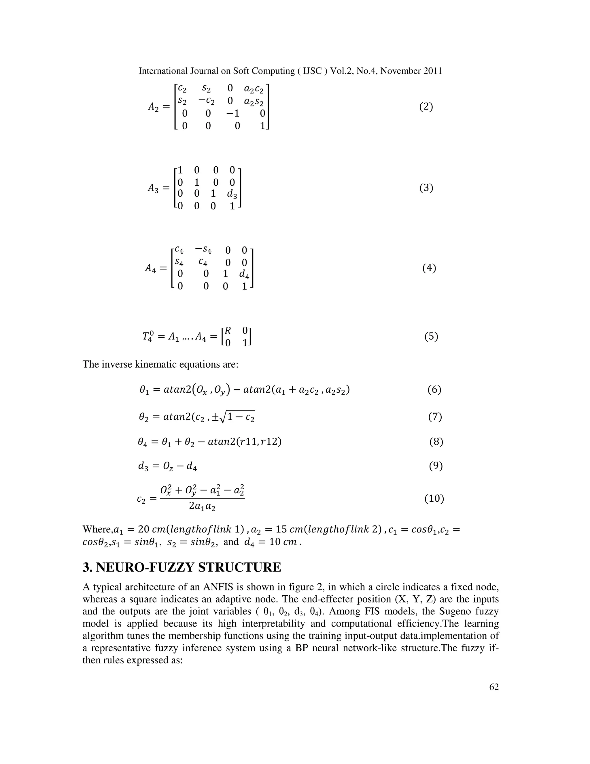
And the A-matrices are as follows.
ܣଵ = ൦
ܿଵ −ݏଵ
ݏଵ ܿଵ
0 ܽଵܿଵ
0 ܽଵݏଵ
0 0
0 0
1 0
0 1
൪ (1)
Link ai αi di θi
1
2
3
4
a1
a2
0
0
0
180
0
0
0
0
d*
d4
θ*
θ*
0
θ*
Table 1. DH Joint parameters for SCARA
Figure 1. DH coordinate frame assignment forthe SCARA manipulator.
4. International Journal on Soft Computing ( IJSC ) Vol.2, No.4, November 2011
62
ܣଶ = ൦
ܿଶ ݏଶ
ݏଶ −ܿଶ
0 ܽଶܿଶ
0 ܽଶݏଶ
0 0
0 0
−1 0
0 1
൪ (2)
ܣଷ =
1 0
0 1
0 0
0 0
0 0
0 0
1 ݀ଷ
0 1
(3)
ܣସ =
ܿସ −ݏସ
ݏସ ܿସ
0 0
0 0
0 0
0 0
1 ݀ସ
0 1
(4)
ܶସ
= ܣଵ … . ܣସ = ቂ
ܴ 0
0 1
ቃ (5)
The inverse kinematic equations are:
ߠଵ = ܽ2݊ܽݐ൫ܱ௫ , ܱ௬൯ − ܽܽ(2݊ܽݐଵ + ܽଶܿଶ , ܽଶݏଶ) (6)
ߠଶ = ܽܿ(2݊ܽݐଶ , ±ඥ1 − ܿଶ (7)
ߠସ = ߠଵ + ߠଶ − ܽ,11ݎ(2݊ܽݐ )21ݎ (8)
݀ଷ = ܱ௭ − ݀ସ (9)
ܿଶ =
ܱ௫
ଶ
+ ܱ௬
ଶ
− ܽଵ
ଶ
− ܽଶ
ଶ
2ܽଵܽଶ
(10)
Where,ܽଵ = 20 ܿ݉(݈݁݊݃ݐℎ݈݂݇݊݅ 1) , ܽଶ = 15 ܿ݉(݈݁݊݃ݐℎ݈݂݇݊݅ 2) , ܿଵ = ܿߠݏଵ,ܿଶ =
ܿߠݏଶ,ݏଵ = ߠ݊݅ݏଵ, ݏଶ = ߠ݊݅ݏଶ, and ݀ସ = 10 ܿ݉ .
3. NEURO-FUZZY STRUCTURE
A typical architecture of an ANFIS is shown in figure 2, in which a circle indicates a fixed node,
whereas a square indicates an adaptive node. The end-effecter position (X, Y, Z) are the inputs
and the outputs are the joint variables ( θ1, θ2, d3, θ4). Among FIS models, the Sugeno fuzzy
model is applied because its high interpretability and computational efficiency.The learning
algorithm tunes the membership functions using the training input-output data.implementation of
a representative fuzzy inference system using a BP neural network-like structure.The fuzzy if-
then rules expressed as:
5. International Journal on Soft Computing ( IJSC ) Vol.2, No.4, November 2011
63
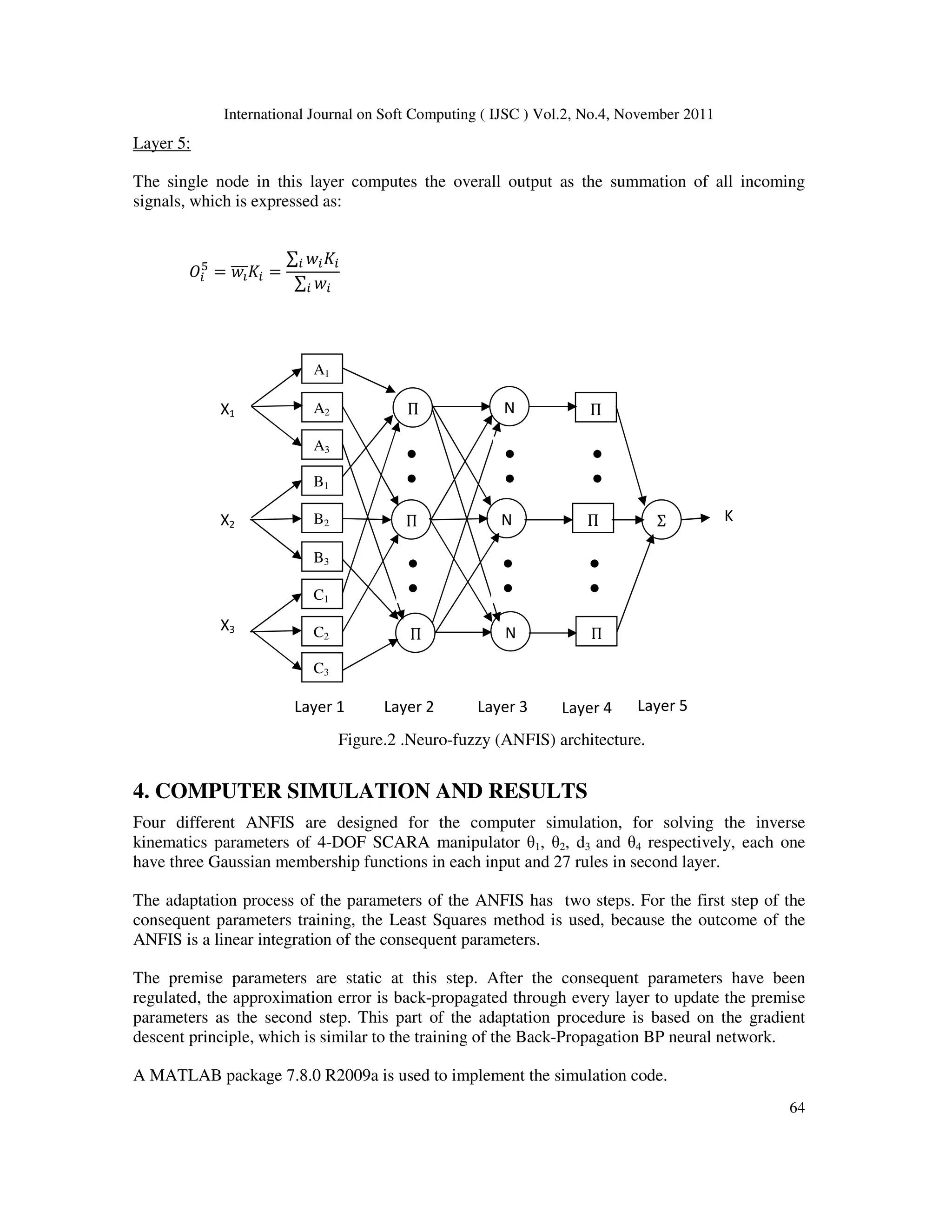
If x is A and y is B and z is C then K= px + qy + sz + r
Where A, B and C are the fuzzy sets in the antecedent, and p, q, s and r are the design parameters
that are determined during the training process.
As in figure 2, the ANFIS comprises of five layers.The role of each layer is briefly presented as
follows:
letܱ
denote the output of node i in layer l, and xi is the ith input of the ANFIS,
i = 1;2;…..; p [10].
Layer1:
Every node i in employ a node function R given by:
ܱ
ଵ
= ܴ(ݔ)
Where ܴ can adopt any fuzzy membership function (MF).
Layer 2:
Every node calculates the firing strength of a rule via multiplication:
ܱ
ଶ
= ݓ = min (ܴ)
Where ݓ represent the activation level of a rule.
Layer 3:
Fixed node i in this layer calculate the ratio of the i-th rules activation level to the total of
all activation level:
ܱ
ଷ
= ݓపതതത =
ݓ
∑ ݓ
Where ݓపതതത is referred to as the normalized firing strengths.
Layer 4:
Every node i has the following function:
ܱ
ସ
= ݓపതതതܭ = ݓపതതത(ݔ + ݍݕ + ݏݖ + ݎ)
Where ݓపതതത is the output of layer 3, and ( pi ,qi,si,ri ) is the parameter set. The parameters in
this layer are referred to as the consequence parameters.
6. International Journal on Soft Computing ( IJSC ) Vol.2, No.4, November 2011
64
Layer 5:
The single node in this layer computes the overall output as the summation of all incoming
signals, which is expressed as:
ܱ
ହ
= ݓపതതതܭ =
∑ ݓܭ
∑ ݓ
4. COMPUTER SIMULATION AND RESULTS
Four different ANFIS are designed for the computer simulation, for solving the inverse
kinematics parameters of 4-DOF SCARA manipulator θ1, θ2, d3 and θ4 respectively, each one
have three Gaussian membership functions in each input and 27 rules in second layer.
The adaptation process of the parameters of the ANFIS has two steps. For the first step of the
consequent parameters training, the Least Squares method is used, because the outcome of the
ANFIS is a linear integration of the consequent parameters.
The premise parameters are static at this step. After the consequent parameters have been
regulated, the approximation error is back-propagated through every layer to update the premise
parameters as the second step. This part of the adaptation procedure is based on the gradient
descent principle, which is similar to the training of the Back-Propagation BP neural network.
A MATLAB package 7.8.0 R2009a is used to implement the simulation code.
Figure.2 .Neuro-fuzzy (ANFIS) architecture.
A1
A2
A3
B1
B2
B3
C1
C2
C3
Π
Π
Π
Π
Π
Π
Σ
N
N
NX3
X1
X2
●
●
●
●
●
●
●
●
●
●
●
●
Layer 1 Layer 2 Layer 3 Layer 4 Layer 5
K
7. International Journal on Soft Computing ( IJSC ) Vol.2, No.4, November 2011
65
Figure 3 shows the error of θ1, θ2 and θ4, figure 4 shows the error of d3, figure 5,figure6, figure 7
and figure 8, shows the testing data of four ANFIS networks for θ1, θ2, d3 and θ4 respectively.
Figure 3. Error of Theta 1 , 2 and 4. Figure 5.Test of Theta 1
Figure 4.Error of d3. Figure 6.Test of Theta 2
Figure 7. Test of d3. Figure 8.Test of Theta 4.
.
8. International Journal on Soft Computing ( IJSC ) Vol.2, No.4, November 2011
66
5. CONCLUSIONS
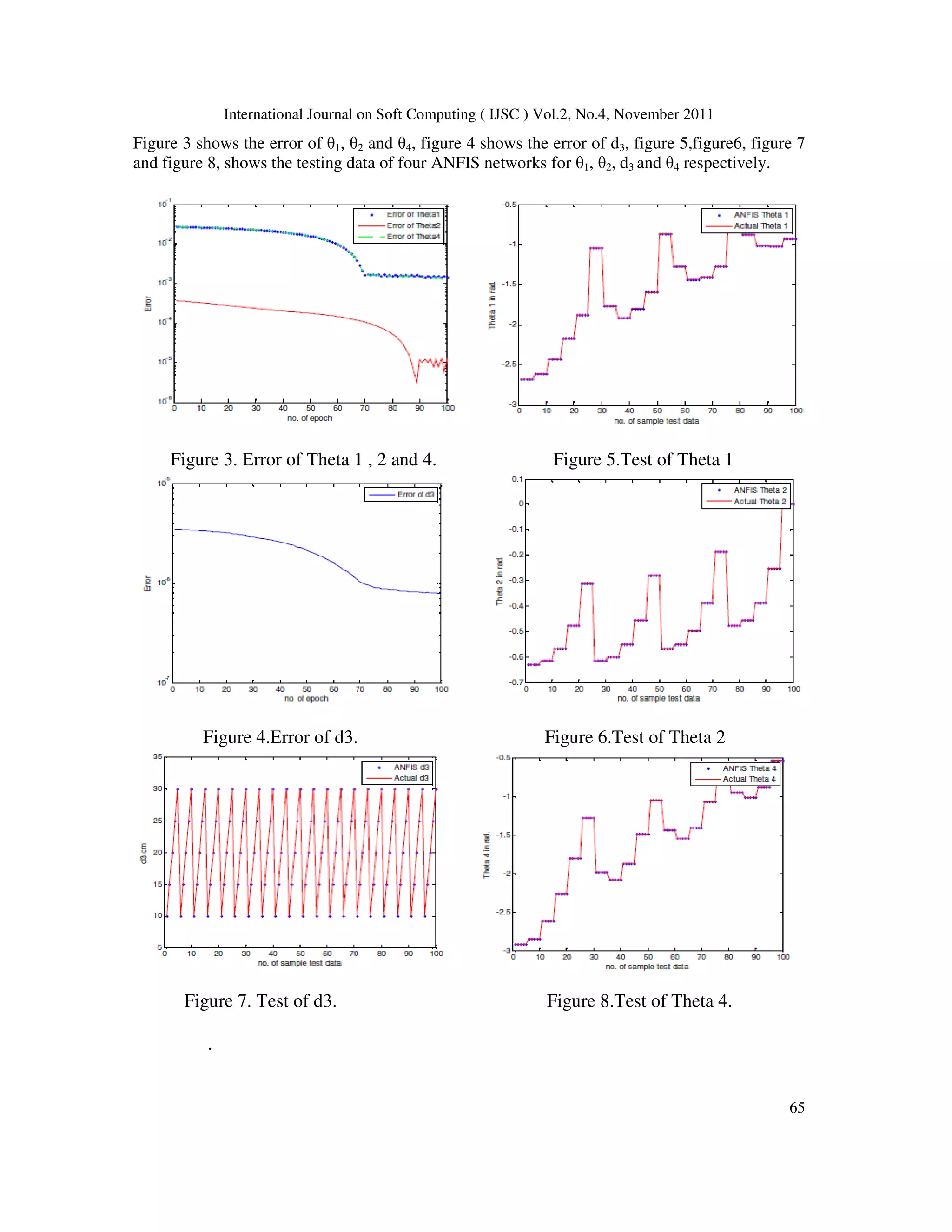
This work demonstrate that is possible to use Simulated ANFIS in order to present a very good
and reliable solution to the Inverse kinematics problem. The results of used ANFIS shows that it
have good and acceptable training error and small number of epoch in training all inverse
kinematic parameters of 4-DOF SCARA manipulator. At the same time, is important to say that
this technique is easy because its very simple to implement and calculating. Then use of ANFIS
give fast and acceptable solution of inverse kinematic parameters.
6. REFERENCES
[1] Mark W. Spong, Seth Hutchinson, and M. Vidyasagar, 2006, “ Robot Modeling and Control “ John
Wiley & Sons, New York.
[2] E. Sariyildiz, and H. Temeltas, 14-17 July, 2009, “ Solution of Inverse Kinematic Problem for Serial
Robot Using Dual Quaterninons and Plucker Coordinates “ IEEE/ASME, Singapore, pp.338-343.
[3] P. Kalra, P.B. Mahapatra, and D.K. Aggarwal, 2003, “ On the Solution of Multimodel Robot Inverse
Kinematic Functions using Real-coded Genetic Algorithms “ IEEE, pp. 1840-1845.
[4] YangshengXu and Michael C. Nechgba, 1993,“ Fuzzy Inverse Kinematic Mapping “ IROS
Conference.
[5] RamakrishnanMukundan, , 2008, “ A Fast Inverse Kinematics Solution for an n-link Joint Chain”
ICITA, pp. 349-354.
[6] Victor H. and etc., October 2010,“ Kinematics for the SCARA and the Cylindrical Manipulators “
ICIC, Vol. 4, No. 5, pp. 1-6.
[7] Samuel R. Buss, October, 2009, “ Introduction to inverse Kinematics with Jacobian Transpose,
Pseudoinverse and Damped Least Squares methods “ University of California press, pp. 1-19.
[8] Takehiko O. and H. Canada, 2010, “Solution for Ill-Posed Inverse Kinematics of Robot
ArmbyNetwork Inversion “ Hindawi Publishing Corporation, Journal of Robotics, Volume 2010,
doi:10.1155/2010/870923.
[9] Panchanand J., 2009, “Novel Artificial Neural Network Application for Prediction of Inverse
Kinematics of Manipulator” M.Sc. Thesis, National Institute of Technology, India.
[10] Dr. Bob John “Adaptive Network Based Fuzzy Inference Systems (ANFIS)
“.www.cse.dmu.ac.uk/~hseker/ANFISnotes.doc
Author
Wesam Mohammed Jasim is presently working as deputy dean in Computer
College, University of Anbar, Ramadi, Iraq, and completed B.Sc. and M.Sc.
in Electrical and Electronic Engineering/Control at 1996 and 2002
respectively, Al-Rasheed College for Engineering and Science, University of
Technology, Baghdad, Iraq.