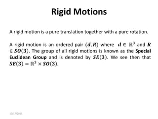
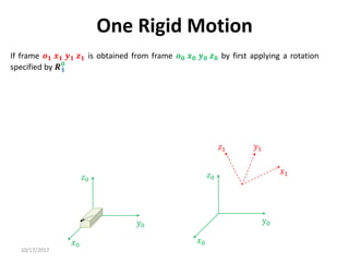
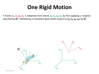
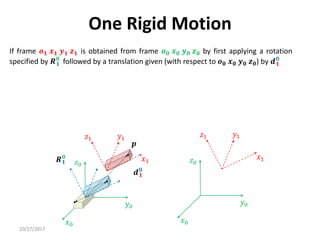
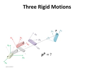
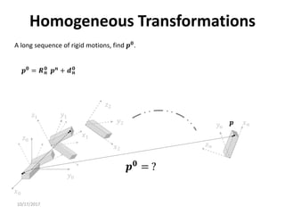
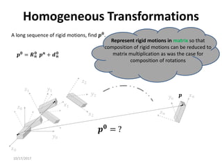
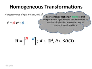
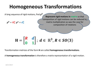
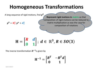
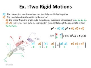
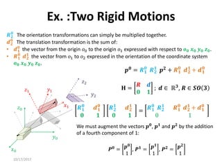
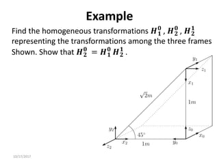
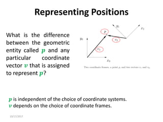
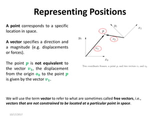
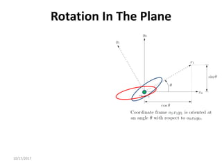
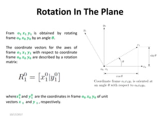
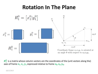
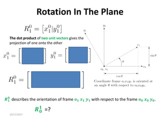
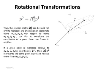
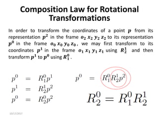
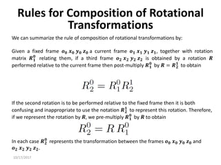
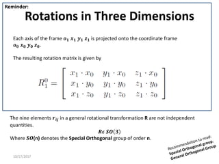
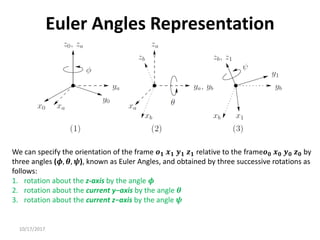
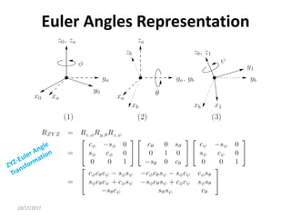
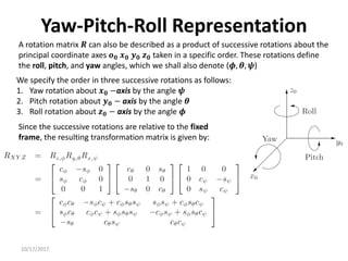
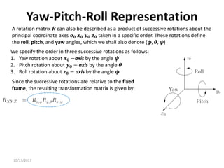
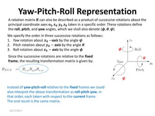
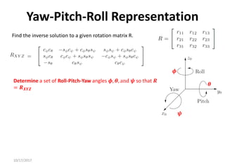
1. Transformation matrices represent coordinate transformations between different coordinate frames attached to rigid objects. They relate the coordinates of a point in one frame to its coordinates in another frame.
2. Rotation matrices specifically describe the orientation of one coordinate frame relative to another. They rotate vectors from one frame to another.
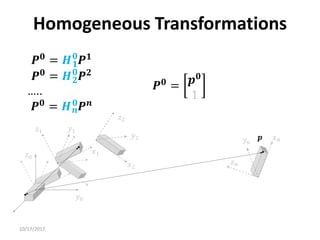
3. Homogeneous transformations combine rotations and translations into a single matrix operation to transform between frames attached to rigid objects that have undergone rotation and translation.


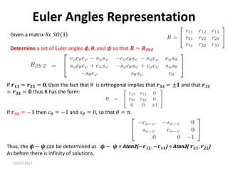
![10/17/2017
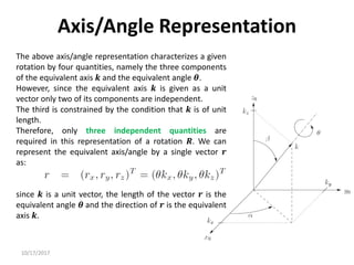
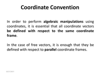
Axis/Angle Representation
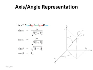
Rotations are not always performed about the principal coordinate axes. We are often
interested in a rotation about an arbitrary axis in space. This provides both a convenient
way to describe rotations, and an alternative parameterization for rotation matrices.
Let 𝒌 = [𝒌𝒙, 𝒌𝒚, 𝒌𝒛]𝑻
, expressed in the frame 𝒐𝟎 𝒙𝟎 𝒚𝟎 𝒛𝟎, be
a unit vector defining an axis. We wish to derive the rotation
matrix 𝑹𝒌,𝜽 representing a rotation of 𝜽 about this axis.
A possible solution is to rotate first 𝒌 by the angles necessary
to align it with 𝒛, then to rotate by 𝜽 about 𝒛, and finally to
rotate by the angels necessary to align the unit vector with
the initial direction.](https://image.slidesharecdn.com/rotationalmatrix-220904072504-1511a411/85/rotational-matrix-pdf-84-320.jpg)
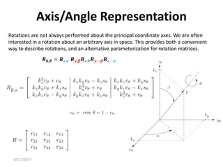
![10/17/2017
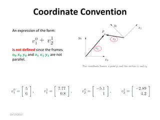
Axis/Angle Representation
Rotations are not always performed about the principal coordinate axes. We are often
interested in a rotation about an arbitrary axis in space. This provides both a convenient
way to describe rotations, and an alternative parameterization for rotation matrices.
Let 𝒌 = [𝒌𝒙, 𝒌𝒚, 𝒌𝒛]𝑻
, expressed in the frame 𝒐𝟎 𝒙𝟎 𝒚𝟎 𝒛𝟎, be
a unit vector defining an axis. We wish to derive the rotation
matrix 𝑹𝒌,𝜽representing a rotation of 𝜽 about this axis.
The sequence of rotations to be made with respect to axes of
fixed frame is the following:
• Align 𝒌 with 𝒛 (which is obtained as the sequence of a
rotation by −𝜶 about 𝒛 and a rotation of −𝜷 about 𝒚).
• Rotate by 𝜽 about 𝒛.
• Realign with the initial direction of 𝒌, which is obtained as
the sequence of a rotation by 𝜷 about 𝒚 and a rotation by
𝜶 about 𝒛.
𝑹𝒌,𝜽 = 𝑹𝒛,𝜶 𝑹𝒚,𝜷𝑹𝒛,𝜽𝑹𝒚,−𝜷𝑹𝒛,−𝜶](https://image.slidesharecdn.com/rotationalmatrix-220904072504-1511a411/85/rotational-matrix-pdf-85-320.jpg)