Downloaded 178 times


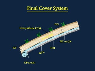


The document discusses solid and hazardous waste classification and management. It outlines different types of wastes and how they are regulated. Hazardous wastes are defined as those exhibiting ignitable, corrosive, reactive or toxic properties above certain thresholds. The document also discusses various waste treatment and disposal methods like incineration, landfilling and the use of geosynthetics in landfill design.


