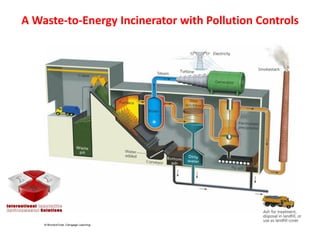
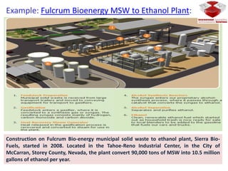
Integrated green technologies for MSW
Prof. Dr. Mamdouh F. Abdel-Sabour
International Innovative Environmental Solution Center (IIESC)
Prof. Emeritus of soil science, Department of Soil and Water Research,
Nuclear Research Center, Atomic Energy Authority.
http://sa.linkedin.com/pub/mamdouh-sabour/2a/999/444/
https://www.researchgate.net/profile/Mamdouh_Abdel-Sabour
wise2007egy@yahoo.com
Content I:
 Automated waste collection system
 Introduction
 Component of generated MSW
 MSW collection
Automated waste collection system
 Capability of one collection system
 Basic concept
 System summary
 Waste inlets
 Waste collection terminal
 Landscape plan for waste collection terminal
 Considering an investment cost
 Product summary
Content II:
 MSW thermo-chemical conversion technologies
 Recycling
 Progress of technology for waste destruction (for non-recyclable MSW)
 Combustion types
 Benefit of WTE
 Incineration
 Carbon and energy considerations
 System components
 WET incinerator with pollution controls
 Pollution controls
 Air pollution control
 Bottom Ash treatment
 Pyrolysis
 Example: Ethanol plant
 Gasification
 Conclusions
Introduction
Most the generated MSW are disposed in landfill which is kind of
wasting a recyclables resources and losses of its energy content,
in addition of the adverse impact of this practices on the
environment as a result of ground water pollution and gaseous
emissions which cause the global warming problem.
Possible Waste Management Options :
 Waste Minimization
 Material Recycling
 Waste Processing (Resource Recovery)
 Waste Transformation
 Sanitary Land filling.
Processing / Treatment should be :
 Technically sound
 Financially viable
 Eco-friendly / Environmental friendly
 Easy to operate & maintain by local
community
 Long term sustainability
The main component of landfill gas are
methane and carbon dioxide. Both
components contribute significantly to
the greenhouse effect and are chiefly
responsible for global temperature rise.
RECOMMENDED APPROACHES TO WASTE
MANAGEMENT
MSW Thermo-chemical
Conversion Technologies
Recycling
Waste disposal technology improves over time as a result of :-
 Higher awareness of environmental, safety and health impacts
 More stringent requirement for compliance with emission
standards
 Land scarcity
 Drawing the most efficient recovery of energy from wastes
 Not least, escalating fuel prices which makes fossil fuel more
expensive for power generation
 Competitive cost of technology over time
Progress of Technology for Waste Destruction
(Non-recyclable MSW)
1 ton of solid waste generate 200 – 300 m3 of landfill gas
1 m3 of landfill gas contains 0.5 m3 of natural gas which
could be used as a fuel to generate 5 kWh energy.
1 ton of CH4 after combustion will generate 24 ton of CO2
Source : Juniper Consultancy Ltd., UK. “Progress Towards Commercialising Waste Gasification” A World Wide Status Report :
Presentation to the Gasification Technology Conference : San Francisco USA 2003 and secondary market information
≤ 5,000c
≤ 1,250c
≤ 1,200c
≤ 700c
-
Advanced Thermal
Gasification System
Fixed or Fluidised Bed
Gasification
Incineration
Burning (Furnace)
Landfill
Waste Destruction
Energy Generation
Waste Destruction
Energy Generation
Waste Destruction
Landfill
Waste Disposal
Landfill
WasteDisposal
-Dump Site Waste Disposal
No GHG
“Zero” Landfill
No GHG
Landfill/Ashes
GHG, Dioxin/Furan
Landfill/Ashes
GHG, Dioxin/Furan
Ashes
GHG
Leachate
GHG
Leachate
Temp.Technology Selection Outcome
Environmental
Issues
TechnologyEvolution
Progress of Technology for Waste Destruction
Combustion Types
• Incineration (energy recovery through
complete oxidation)
Mass Burn
Refuse Derived Fuel (RDF)
• Pyrolysis
• Gasification
• Plasma arc (advanced thermal conversion)
Technology improvement naturally draws increased capital cost but …
the environmental and health improvements supersede the
conventional waste disposal technology
Dumping Landfill Sanitary
Landfill
Incinerator Gasification
Advanced
Thermal
Gasification
SystemWater source
contamination
Air pollution
impacts
Overall
environmental
costs
Various waste
disposal
technologies
Uncontrolled leachate: high risk of
water contamination
Moderate risk of water
contamination
Controlled leachate:
Minimised water contamination
Moderate to high risk of air
pollution from methane
Moderate risk of air
pollution from methane
Risk of air pollution from furans
& dioxins presents
No risk of
air pollution
Prospect for
energy recovery No prospect of recovery of energy
waste
Minimal prospect of recovery
of energy from waste
HIGH
High prospect of recovery of energy waste
(energy recovery is maximised)
MODERATE LOW NEGLIGLIBLE
Tipping
Fees per
Ton
Benefits of WTE
Incineration
Tonne of waste creates 3.5 MW of energy during incineration (eq.
to 300 kg of fuel oil) powers 70 homes
Carbon and Energy Considerations
System Components
• Refuse receipt/storage
• Refuse feeding
• Grate system
• Air supply
• Furnace
• Boiler
A Waste-to-Energy Incinerator with Pollution Controls
Flue Gas Pollutants
Particulates
Acid Gases
NOx
CO
Organic Hazardous Air Pollutants
Metal Hazardous Air Pollutants
Particulates
Solid
Condensable
Causes
 Too low of a comb (incomplete comb)
 Insufficient oxygen or overabundant EA
(too high T)
 Insufficient mixing or residence time
 Too much turbulence, entrainment of
particulates
Control
1) Cyclones - not effective for removal
of small particulates
2) Electrostatic precipitator
3) Fabric Filters (baghouses)
Metals
 Removed with particulates
 Mercury remains volatilized
 Tough to remove from flue gas
 Remove source or use activated carbon
(along with dioxins)
Acid Gases
From Cl, S, N, Fl in refuse (in plastics,
textiles, rubber, yd waste, paper)
Uncontrolled incineration - 18-20% HCl
with pH 2
Acid gas scrubber (SO2, HCl, HFl)
usually ahead of ESP or baghouse
1) Wet scrubber
2) Spray dryer
3) Dry scrubber injectors
Nitrogen removal
Source removal to avoid fuel NOx
production
T < 1500 F to avoid thermal NOx
Denox sytems - selective catalytic
reaction via injection of ammonia
Pollution Controls
Air Pollution Control
• Remove certain waste components
• Good Combustion Practices
• Emission Control Devices
Electrostatic Precipitator
Bag-houses
Acid Gas Scrubbers
Wet scrubber
Dry scrubber
Chemicals added in slurry to neutralize acids
Activated Carbon
Selective Non-catalytic Reduction
Schematic Presentation of Bottom Ash Treatment
1. Construction fill
2. Road construction
3. Landfill daily cover
4. Cement block production
5. Treatment of acid mine drainage
Ash Reuse OptionsBottom Ash – recovered from combustion
chamber
Heat Recovery Ash – collected in the heat
recovery system (boiler, economizer, superheater)
Fly Ash – Particulate matter removed prior to
sorbents
Air Pollution Control Residues – usually combined
with fly ash
Pyrolysis
Pyrolyzer—Mitsui R21
Thermal degradation of carbonaceous materials
Lower temperature than gasification (750 – 1500oF)
Absence or limited oxygen
Products are pyrolitic oils and gas, solid char
Distribution of products depends on temperature
Pyrolysis oil used for (after appropriate post-treatment):
liquid fuels,
chemicals,
adhesives, and other products.
A number of processes directly combust pyrolysis gases, oils, and char
Example: Fulcrum Bioenergy MSW to Ethanol Plant:
Construction on Fulcrum Bio-energy municipal solid waste to ethanol plant, Sierra Bio-
Fuels, started in 2008. Located in the Tahoe-Reno Industrial Center, in the City of
McCarran, Storey County, Nevada, the plant convert 90,000 tons of MSW into 10.5 million
gallons of ethanol per year.
pyrolysis
Gasification
Flexibility of Gasification
Thermo-select (Gasification and Pyrolysis)
• Recovers a synthesis gas, utilizable glass-like minerals,
metals rich in iron and sulfur from municipal solid
waste, commercial waste, industrial waste and
hazardous waste
• High temperature gasification of the organic waste
constituents and direct fusion of the inorganic
components.
• Water, salt and zinc concentrate are produced as
usable raw materials during the process water
treatment.
• No ashes, slag or filter dusts
• 100,000 tpd plant in Japan operating since 1999
Thermoselect
(http://www.thermoselect.com/index.cfm)
□Utilizes Thermal Energy developed by Plasma Torches
at Temperatures ≤5,500 Degrees Celsius
□Multiple Feedstock
□ All Organic Material is Gasified to form a Synthetic
Gas (“Syngas”)
□All Inorganic Materials is Vitrified into Inert “High
Grade Aggregate Slag”
□Calorific Energy and Sensible Heat from the Syngas is
Recovered and transformed into Electrical Energy
Advanced Thermal Gasification System
Conclusions
• Combustion remains predominant thermal
technology for MSW conversion with realized
improvements in emissions
• Gasification and Pyrolysis systems now in
commercial scale operation but industry still
emerging
• Advanced Thermal Gasification System is Clean
Development Mechanism under Kyoto Protocol.
Capable for qualification as CDM project, i.e.,
reduction of emission of methane typically from
landfills and reduction of CO2 emission from
avoidance of use of fossil fuels for power
generation.
• Improved environmental data needed on
operating systems
• Comprehensive environmental or life cycle
assessments should be completed
integrated green Technologies for MSW

integrated green Technologies for MSW

  • 1.
    Integrated green technologiesfor MSW Prof. Dr. Mamdouh F. Abdel-Sabour International Innovative Environmental Solution Center (IIESC) Prof. Emeritus of soil science, Department of Soil and Water Research, Nuclear Research Center, Atomic Energy Authority. http://sa.linkedin.com/pub/mamdouh-sabour/2a/999/444/ https://www.researchgate.net/profile/Mamdouh_Abdel-Sabour wise2007egy@yahoo.com
  • 2.
    Content I:  Automatedwaste collection system  Introduction  Component of generated MSW  MSW collection Automated waste collection system  Capability of one collection system  Basic concept  System summary  Waste inlets  Waste collection terminal  Landscape plan for waste collection terminal  Considering an investment cost  Product summary
  • 3.
    Content II:  MSWthermo-chemical conversion technologies  Recycling  Progress of technology for waste destruction (for non-recyclable MSW)  Combustion types  Benefit of WTE  Incineration  Carbon and energy considerations  System components  WET incinerator with pollution controls  Pollution controls  Air pollution control  Bottom Ash treatment  Pyrolysis  Example: Ethanol plant  Gasification  Conclusions
  • 4.
  • 5.
    Most the generatedMSW are disposed in landfill which is kind of wasting a recyclables resources and losses of its energy content, in addition of the adverse impact of this practices on the environment as a result of ground water pollution and gaseous emissions which cause the global warming problem. Possible Waste Management Options :  Waste Minimization  Material Recycling  Waste Processing (Resource Recovery)  Waste Transformation  Sanitary Land filling. Processing / Treatment should be :  Technically sound  Financially viable  Eco-friendly / Environmental friendly  Easy to operate & maintain by local community  Long term sustainability The main component of landfill gas are methane and carbon dioxide. Both components contribute significantly to the greenhouse effect and are chiefly responsible for global temperature rise. RECOMMENDED APPROACHES TO WASTE MANAGEMENT
  • 16.
  • 17.
  • 18.
    Waste disposal technologyimproves over time as a result of :-  Higher awareness of environmental, safety and health impacts  More stringent requirement for compliance with emission standards  Land scarcity  Drawing the most efficient recovery of energy from wastes  Not least, escalating fuel prices which makes fossil fuel more expensive for power generation  Competitive cost of technology over time Progress of Technology for Waste Destruction (Non-recyclable MSW) 1 ton of solid waste generate 200 – 300 m3 of landfill gas 1 m3 of landfill gas contains 0.5 m3 of natural gas which could be used as a fuel to generate 5 kWh energy. 1 ton of CH4 after combustion will generate 24 ton of CO2
  • 19.
    Source : JuniperConsultancy Ltd., UK. “Progress Towards Commercialising Waste Gasification” A World Wide Status Report : Presentation to the Gasification Technology Conference : San Francisco USA 2003 and secondary market information ≤ 5,000c ≤ 1,250c ≤ 1,200c ≤ 700c - Advanced Thermal Gasification System Fixed or Fluidised Bed Gasification Incineration Burning (Furnace) Landfill Waste Destruction Energy Generation Waste Destruction Energy Generation Waste Destruction Landfill Waste Disposal Landfill WasteDisposal -Dump Site Waste Disposal No GHG “Zero” Landfill No GHG Landfill/Ashes GHG, Dioxin/Furan Landfill/Ashes GHG, Dioxin/Furan Ashes GHG Leachate GHG Leachate Temp.Technology Selection Outcome Environmental Issues TechnologyEvolution Progress of Technology for Waste Destruction
  • 20.
    Combustion Types • Incineration(energy recovery through complete oxidation) Mass Burn Refuse Derived Fuel (RDF) • Pyrolysis • Gasification • Plasma arc (advanced thermal conversion)
  • 21.
    Technology improvement naturallydraws increased capital cost but … the environmental and health improvements supersede the conventional waste disposal technology Dumping Landfill Sanitary Landfill Incinerator Gasification Advanced Thermal Gasification SystemWater source contamination Air pollution impacts Overall environmental costs Various waste disposal technologies Uncontrolled leachate: high risk of water contamination Moderate risk of water contamination Controlled leachate: Minimised water contamination Moderate to high risk of air pollution from methane Moderate risk of air pollution from methane Risk of air pollution from furans & dioxins presents No risk of air pollution Prospect for energy recovery No prospect of recovery of energy waste Minimal prospect of recovery of energy from waste HIGH High prospect of recovery of energy waste (energy recovery is maximised) MODERATE LOW NEGLIGLIBLE Tipping Fees per Ton Benefits of WTE
  • 22.
  • 23.
    Tonne of wastecreates 3.5 MW of energy during incineration (eq. to 300 kg of fuel oil) powers 70 homes Carbon and Energy Considerations
  • 24.
    System Components • Refusereceipt/storage • Refuse feeding • Grate system • Air supply • Furnace • Boiler
  • 25.
    A Waste-to-Energy Incineratorwith Pollution Controls
  • 26.
    Flue Gas Pollutants Particulates AcidGases NOx CO Organic Hazardous Air Pollutants Metal Hazardous Air Pollutants Particulates Solid Condensable Causes  Too low of a comb (incomplete comb)  Insufficient oxygen or overabundant EA (too high T)  Insufficient mixing or residence time  Too much turbulence, entrainment of particulates Control 1) Cyclones - not effective for removal of small particulates 2) Electrostatic precipitator 3) Fabric Filters (baghouses) Metals  Removed with particulates  Mercury remains volatilized  Tough to remove from flue gas  Remove source or use activated carbon (along with dioxins) Acid Gases From Cl, S, N, Fl in refuse (in plastics, textiles, rubber, yd waste, paper) Uncontrolled incineration - 18-20% HCl with pH 2 Acid gas scrubber (SO2, HCl, HFl) usually ahead of ESP or baghouse 1) Wet scrubber 2) Spray dryer 3) Dry scrubber injectors Nitrogen removal Source removal to avoid fuel NOx production T < 1500 F to avoid thermal NOx Denox sytems - selective catalytic reaction via injection of ammonia Pollution Controls
  • 27.
    Air Pollution Control •Remove certain waste components • Good Combustion Practices • Emission Control Devices Electrostatic Precipitator Bag-houses Acid Gas Scrubbers Wet scrubber Dry scrubber Chemicals added in slurry to neutralize acids Activated Carbon Selective Non-catalytic Reduction
  • 28.
    Schematic Presentation ofBottom Ash Treatment 1. Construction fill 2. Road construction 3. Landfill daily cover 4. Cement block production 5. Treatment of acid mine drainage Ash Reuse OptionsBottom Ash – recovered from combustion chamber Heat Recovery Ash – collected in the heat recovery system (boiler, economizer, superheater) Fly Ash – Particulate matter removed prior to sorbents Air Pollution Control Residues – usually combined with fly ash
  • 29.
    Pyrolysis Pyrolyzer—Mitsui R21 Thermal degradationof carbonaceous materials Lower temperature than gasification (750 – 1500oF) Absence or limited oxygen Products are pyrolitic oils and gas, solid char Distribution of products depends on temperature Pyrolysis oil used for (after appropriate post-treatment): liquid fuels, chemicals, adhesives, and other products. A number of processes directly combust pyrolysis gases, oils, and char
  • 30.
    Example: Fulcrum BioenergyMSW to Ethanol Plant: Construction on Fulcrum Bio-energy municipal solid waste to ethanol plant, Sierra Bio- Fuels, started in 2008. Located in the Tahoe-Reno Industrial Center, in the City of McCarran, Storey County, Nevada, the plant convert 90,000 tons of MSW into 10.5 million gallons of ethanol per year.
  • 31.
  • 32.
  • 33.
  • 34.
    Thermo-select (Gasification andPyrolysis) • Recovers a synthesis gas, utilizable glass-like minerals, metals rich in iron and sulfur from municipal solid waste, commercial waste, industrial waste and hazardous waste • High temperature gasification of the organic waste constituents and direct fusion of the inorganic components. • Water, salt and zinc concentrate are produced as usable raw materials during the process water treatment. • No ashes, slag or filter dusts • 100,000 tpd plant in Japan operating since 1999
  • 35.
  • 36.
    □Utilizes Thermal Energydeveloped by Plasma Torches at Temperatures ≤5,500 Degrees Celsius □Multiple Feedstock □ All Organic Material is Gasified to form a Synthetic Gas (“Syngas”) □All Inorganic Materials is Vitrified into Inert “High Grade Aggregate Slag” □Calorific Energy and Sensible Heat from the Syngas is Recovered and transformed into Electrical Energy Advanced Thermal Gasification System
  • 37.
    Conclusions • Combustion remainspredominant thermal technology for MSW conversion with realized improvements in emissions • Gasification and Pyrolysis systems now in commercial scale operation but industry still emerging • Advanced Thermal Gasification System is Clean Development Mechanism under Kyoto Protocol. Capable for qualification as CDM project, i.e., reduction of emission of methane typically from landfills and reduction of CO2 emission from avoidance of use of fossil fuels for power generation. • Improved environmental data needed on operating systems • Comprehensive environmental or life cycle assessments should be completed