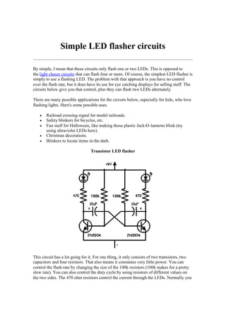
This document discusses several simple LED flasher circuits that can be used to flash one or two LEDs. The simplest circuit uses a flashing LED with no control over the flash rate. The transistor LED flasher circuit consists of two transistors, two capacitors and four resistors and allows control over the flash rate and duty cycle. The basic LED flasher circuit uses a NE555 timer IC and allows for a variable flash rate. Finally, the document discusses the now discontinued LM3909 LED flasher chip which was not found to be very useful.
A digital clock is a type of clock that displays the time digitally (i.e. in numerals or other symbols), as opposed to an analog clock, where the time is indicated by the positions of rotating hands.
Infrared IR Sensor Circuit Diagram and Working Principleelprocus
An infrared sensor is an electronic device, that emits in order to sense some aspects of the surroundings. An IR sensor can measure the heat of an object as well as detects the motion. These types of sensors measures only infrared radiation, rather than emitting it that is called as a passive IR sensor. Usually in the infrared spectrum, all the objects radiate some form of thermal radiations.
1.Introduction
The 555 IC was designed in 1971 by Hans Camenzind under contract to SigNetics Corporation.
555 timer is a highly stable circuit used to generate time delays, or Oscillations.
A single 555 timer can provide time delay ranging from microseconds to hours.
It operates from a wide range of power supplies ranging from + 5 Volts to + 18 Volts supply voltage.
2.Pin Configuration
3.Working of Pin
4.555 Integral circuit
5.Operating modes of IC
6. Bistable Mode
In bistable (also called Schmitt trigger) mode, the 555 timer acts as a basic flip-flop.
The trigger and reset inputs (pins 2 and 4 respectively on a 555) are held high via pull-up resistors while the threshold input (pin 6) is simply floating.
Thus configured, pulling the trigger momentarily to ground acts as a 'set' and transitions the output pin (pin 3) to Vcc (high state).
Pulling the reset input to ground acts as a 'reset' and transitions the output pin to ground (low state). No timing capacitors
Pin 5 (control voltage) is connected to ground via a small-value capacitor (usually 0.01 to 0.1 μF). Pin 7 (discharge) is left floating
7.Monostable Mode
Pulse generator circuit which the period is calculated from RC network and connected to external of 555 timer
Stable when the output logic LOW (logic = 0)
When a pulse is trigger at pin 2 (normally negative trigger pulse), timer output will change to HIGH (+Vs) for a while and change to LOW (stable condition). The condition will continue LOW until pulse is trigger again.
The timing period is triggered (started) when trigger input (555 pin 2) is less than 1/3 Vs, this makes the output high (+Vs) and the capacitor C1 starts to charge through resistor R1. Once the time period has started further trigger pulses are ignored.
The threshold input (555 pin 6) monitors the voltage across C1 and when this reaches 2/3 Vs the time period over and the output becomes LOW,
At the same time discharge (555 pin 7) is connected to 0V, discharging the capacitor ready for the next trigger.
8.Astable Mode
Astable multivibrators are also known as Free-running Multivibrator.
Astable do not need trigger pulse for external to change the output.
The period for LOW and HIGH can be calculated based on resistor and capacitor value that connected at outside of timer.
9.Applications
Schmitt trigger
PPM
PWM
Linear Ramp generator
Precision Timing
Pulse Generation
Time Delay Generation
Sequential Timing
Used as a quad timer
10. Conclusion
Hence 555 IC timer can produce very accurate and stable time delays, from microseconds to hours. It can be used with supply voltage varying from 5 to 18 V. Timer can be used in monostable mode of operation or astable mode of operation. Its various applications include waveform generator, missing pulse detector, frequency divider, pulse width modulator, burglar alarm, FSK generator, ramp generator, pulse position modulator etc.
VHDL (VHSIC Hardware Description Language) is becoming increasingly popular as a way to capture complex digital electronic circuits for both simulation and synthesis. Digital circuits captured using VHDL can be easily simulated, are more likely to be synthesizable into multiple target technologies, and can be archived for later modification and reuse.
this ppt only for beginner who want to understand concept of Timer counter operation of LPC2148 step by step.
hope it may help u.
always welcoming ur suggestion.
Part of Lecture series on EE321N, Power Electronics-I delivered by me during Fifth Semester of B.Tech. Electrical Engg., 2012
Z H College of Engg. & Technology, Aligarh Muslim University, Aligarh
Please comment and feel free to ask anything related. Thanks!
The range
An operator system cannot be said to be complete without a flashing light that warns when the gate or door is moving, to ensure maximum safety for users. Came's offer meets all needs in terms of reliability, design, energy
savings, and always in compliance with European Regulations.
The schematic presented here is a project of an LED flasher circuit using 555 timer IC. 555 is a famous timer IC
manufactured in 8 pin dip package. In this circuit the IC is used in a flip flop flasher mode. The circuit is using 24 LEDsand will blink each set of 12 LEDs one by one.
Hi, im Perlis polytechnic student, and now i undergo last semester already. And i taken one interesting subject is CMOS IC design. So this is one of lab work that i uploading. Using L-Edit to design NAND gate.
Mostly and must needed equipment for water tank in our house or industry. Water level indicator not only indicates the water level but also switch OFF and ON the power supply to water pump automatically. Most Demanded and easiest project to built. Can be constructed by beginner.
A book for students and hobbyists to learn basic electronics through practical presentable circuits.
A handy guide for school science fair projects or for making personal hobby gadgets.
Design new panels and make new circuit designs.
For more info : please visit www.hobbyelectronics.in
-introduction:
Many of the people have a phobia of darkness, so to assist them in such situation, we have explained a simple circuit. It will automatically turn on street light in the way of LEDs or bulb coupled with relay.
Automatic street light system is very common nowadays as it provides intelligent street lighting mechanism. It provides light automatically during night without any human interference. These energy saving street lights make use of incandescent lamps instead of LEDs .So here I will study with you how to make an electronic circuit for street light automation using simple electronics component .
- Objectives of the Project
Reducing the wastage of power
Reducing physical efforts
Improve the system in our daily life
-CIRCUIT WORK PRINCIPLE:
The lamp(street bulb) should remain OFF during daytime and turn ON automatically during night. The unique property of light depended resistor is utilized here. LDR is a variable resistor which has very low resistance in the presence of light and very high resistance in the absence of light.In this circuit, we create a potential divider network with an ordinary resistor in one arm and a LDR on the other arm. According to Ohm’s law (V=IR), voltage drop across the resistor increases when its resistance increases. Here the drop across LDR varies with changes in light intensity. That is voltage drop across the LDR is minimum in the presence of light and maximum in the absence of light
Many of the people have a phobia of darkness, so to assist them in such situation, we have explained a simple circuit. It will automatically turn on street light in the way of LEDs or bulb coupled with relay. Working this circuit is very much easy and also the power consumed by the circuit is very low because of the very few components used in the circuit.
JOULE THIEF WHICH GIVES LIFE TO DEAD BATTERIES!!!Sanjay4502
It is very important that buying a set of batteries for household purposes. How about draining the last drop of energy from a battery which you have declared dead? This slideshare does that. See to it!!!!!!!!!
Elevating Tactical DDD Patterns Through Object CalisthenicsDorra BARTAGUIZ
After immersing yourself in the blue book and its red counterpart, attending DDD-focused conferences, and applying tactical patterns, you're left with a crucial question: How do I ensure my design is effective? Tactical patterns within Domain-Driven Design (DDD) serve as guiding principles for creating clear and manageable domain models. However, achieving success with these patterns requires additional guidance. Interestingly, we've observed that a set of constraints initially designed for training purposes remarkably aligns with effective pattern implementation, offering a more ‘mechanical’ approach. Let's explore together how Object Calisthenics can elevate the design of your tactical DDD patterns, offering concrete help for those venturing into DDD for the first time!
Neuro-symbolic is not enough, we need neuro-*semantic*Frank van Harmelen
Neuro-symbolic (NeSy) AI is on the rise. However, simply machine learning on just any symbolic structure is not sufficient to really harvest the gains of NeSy. These will only be gained when the symbolic structures have an actual semantics. I give an operational definition of semantics as “predictable inference”.
All of this illustrated with link prediction over knowledge graphs, but the argument is general.
State of ICS and IoT Cyber Threat Landscape Report 2024 previewPrayukth K V
The IoT and OT threat landscape report has been prepared by the Threat Research Team at Sectrio using data from Sectrio, cyber threat intelligence farming facilities spread across over 85 cities around the world. In addition, Sectrio also runs AI-based advanced threat and payload engagement facilities that serve as sinks to attract and engage sophisticated threat actors, and newer malware including new variants and latent threats that are at an earlier stage of development.
The latest edition of the OT/ICS and IoT security Threat Landscape Report 2024 also covers:
State of global ICS asset and network exposure
Sectoral targets and attacks as well as the cost of ransom
Global APT activity, AI usage, actor and tactic profiles, and implications
Rise in volumes of AI-powered cyberattacks
Major cyber events in 2024
Malware and malicious payload trends
Cyberattack types and targets
Vulnerability exploit attempts on CVEs
Attacks on counties – USA
Expansion of bot farms – how, where, and why
In-depth analysis of the cyber threat landscape across North America, South America, Europe, APAC, and the Middle East
Why are attacks on smart factories rising?
Cyber risk predictions
Axis of attacks – Europe
Systemic attacks in the Middle East
Download the full report from here:
https://sectrio.com/resources/ot-threat-landscape-reports/sectrio-releases-ot-ics-and-iot-security-threat-landscape-report-2024/
Accelerate your Kubernetes clusters with Varnish CachingThijs Feryn
A presentation about the usage and availability of Varnish on Kubernetes. This talk explores the capabilities of Varnish caching and shows how to use the Varnish Helm chart to deploy it to Kubernetes.
This presentation was delivered at K8SUG Singapore. See https://feryn.eu/presentations/accelerate-your-kubernetes-clusters-with-varnish-caching-k8sug-singapore-28-2024 for more details.
Builder.ai Founder Sachin Dev Duggal's Strategic Approach to Create an Innova...Ramesh Iyer
In today's fast-changing business world, Companies that adapt and embrace new ideas often need help to keep up with the competition. However, fostering a culture of innovation takes much work. It takes vision, leadership and willingness to take risks in the right proportion. Sachin Dev Duggal, co-founder of Builder.ai, has perfected the art of this balance, creating a company culture where creativity and growth are nurtured at each stage.
The Art of the Pitch: WordPress Relationships and SalesLaura Byrne
Clients don’t know what they don’t know. What web solutions are right for them? How does WordPress come into the picture? How do you make sure you understand scope and timeline? What do you do if sometime changes?
All these questions and more will be explored as we talk about matching clients’ needs with what your agency offers without pulling teeth or pulling your hair out. Practical tips, and strategies for successful relationship building that leads to closing the deal.
UiPath Test Automation using UiPath Test Suite series, part 3DianaGray10
Welcome to UiPath Test Automation using UiPath Test Suite series part 3. In this session, we will cover desktop automation along with UI automation.
Topics covered:
UI automation Introduction,
UI automation Sample
Desktop automation flow
Pradeep Chinnala, Senior Consultant Automation Developer @WonderBotz and UiPath MVP
Deepak Rai, Automation Practice Lead, Boundaryless Group and UiPath MVP
Software Delivery At the Speed of AI: Inflectra Invests In AI-Powered QualityInflectra
In this insightful webinar, Inflectra explores how artificial intelligence (AI) is transforming software development and testing. Discover how AI-powered tools are revolutionizing every stage of the software development lifecycle (SDLC), from design and prototyping to testing, deployment, and monitoring.
Learn about:
• The Future of Testing: How AI is shifting testing towards verification, analysis, and higher-level skills, while reducing repetitive tasks.
• Test Automation: How AI-powered test case generation, optimization, and self-healing tests are making testing more efficient and effective.
• Visual Testing: Explore the emerging capabilities of AI in visual testing and how it's set to revolutionize UI verification.
• Inflectra's AI Solutions: See demonstrations of Inflectra's cutting-edge AI tools like the ChatGPT plugin and Azure Open AI platform, designed to streamline your testing process.
Whether you're a developer, tester, or QA professional, this webinar will give you valuable insights into how AI is shaping the future of software delivery.
Transcript: Selling digital books in 2024: Insights from industry leaders - T...BookNet Canada
The publishing industry has been selling digital audiobooks and ebooks for over a decade and has found its groove. What’s changed? What has stayed the same? Where do we go from here? Join a group of leading sales peers from across the industry for a conversation about the lessons learned since the popularization of digital books, best practices, digital book supply chain management, and more.
Link to video recording: https://bnctechforum.ca/sessions/selling-digital-books-in-2024-insights-from-industry-leaders/
Presented by BookNet Canada on May 28, 2024, with support from the Department of Canadian Heritage.
Securing your Kubernetes cluster_ a step-by-step guide to success !KatiaHIMEUR1
Today, after several years of existence, an extremely active community and an ultra-dynamic ecosystem, Kubernetes has established itself as the de facto standard in container orchestration. Thanks to a wide range of managed services, it has never been so easy to set up a ready-to-use Kubernetes cluster.
However, this ease of use means that the subject of security in Kubernetes is often left for later, or even neglected. This exposes companies to significant risks.
In this talk, I'll show you step-by-step how to secure your Kubernetes cluster for greater peace of mind and reliability.
Generating a custom Ruby SDK for your web service or Rails API using Smithyg2nightmarescribd
Have you ever wanted a Ruby client API to communicate with your web service? Smithy is a protocol-agnostic language for defining services and SDKs. Smithy Ruby is an implementation of Smithy that generates a Ruby SDK using a Smithy model. In this talk, we will explore Smithy and Smithy Ruby to learn how to generate custom feature-rich SDKs that can communicate with any web service, such as a Rails JSON API.
When stars align: studies in data quality, knowledge graphs, and machine lear...
Simple led flasher circuits
1. Simple LED flasher circuits
By simple, I mean that these circuits only flash one or two LEDs. This is opposed to
the light chaser circuits that can flash four or more. Of course, the simplest LED flasher is
simply to use a flashing LED. The problem with that approach is you have no control
over the flash rate, but it does have its use for eye catching displays for selling stuff. The
circuits below give you that control, plus they can flash two LEDs alternately.
There are many possible applications for the circuits below, especially for kids, who love
flashing lights. Here's some possible uses.
Railroad crossing signal for model railroads.
Safety blinkers for bicycles, etc.
Fun stuff for Halloween, like making those plastic Jack-O-lanterns blink (try
using ultraviolet LEDs here).
Christmas decorations.
Blinkers to locate items in the dark.
Transistor LED flasher
This circuit has a lot going for it. For one thing, it only consists of two transistors, two
capacitors and four resistors. That also means it consumes very little power. You can
control the flash rate by changing the size of the 100k resistors (100k makes for a pretty
slow rate). You can also control the duty cycle by using resistors of different values on
the two sides. The 470 ohm resistors control the current through the LEDs. Normally you
2. want to limit this to 20mA, but to conserve battery power, you may need to limit it even
further. You can also connect several LEDs in series, instead of using only one for each
side. With red LEDs (1 per side) and the values shown, the circuit draws about 11mA.
Here's what the actual circuit looks like:
On this circuit, the green wires connect to the LEDs, but you can mount them on the
actual circuit board for some applications. The picture is about twice actual size. Here is
an example of the use of this circuit:
Basic LED flasher circuit using NE555 timer IC
3. This circuit consumes more power, but it's advantage is when you need a variable flash
rate, like for strobe circuits. You can actually use this circuit as a remote control for
strobes that have a remote input. Of course, it has many other applications besides strobes.
R1, R2, C1 and the supply voltage determine the flash rate. Using a regulated
power supply will do much to insure a stable flash rate. For a variable flash rate,
replace R1 with a 1 megohm pot in series with a 22k resistor.
The duty cycle of the circuit (the percentage of the time LED 1 is on to the time it
is off during each cycle) is deterimed by the ratio of R1 to R2. If the value of R1
is low in relationship to R2, the duty cycle will be near 50 percent. If you use both
LEDs, you will probably want a 50 percent duty cycle. On the other hand, if R2 is
low compared to R1, the duty cycle will be less than 50 percent. This is useful to
conserve battery life, or to produce a strobe type effect, when only LED1 is used.
The NE555 timer chip can be damaged by reverse polarity voltage being applied
to it. You can make the circuit goof proof by placing a diode in series with one of
the supply leads.
The purpose of R3 and R4 is to limit current through the LEDs to the maximum
they can handle (usually 20 milliamps). You should select the value of these
according to the supply voltage. 470 ohms works well with a supply voltage of 912 volts. You will need to reduce the value for lower supply voltages.
Rainbow Kits offers several kits to build the above circuit. You can also order
these kits from RadioShack.com. The Radio Shack catalog numbers (and web
pages) are as follows: standard kit with two 5mm red LEDs, (990-0067), kit with
two red, two green and two yellow 3mm LEDs, (990-0063), kit with jumbo green
LEDs, (990-0048), kit with jumbo red LEDs, (990-0049). You can also buy all
the parts to build the circuit at your local Radio Shack store, including a circuit
board (276-159B).