Downloaded 147 times

![Programming a PIC Microcontroller
Page 1 of 24
1. Introduction
1.1 Purpose
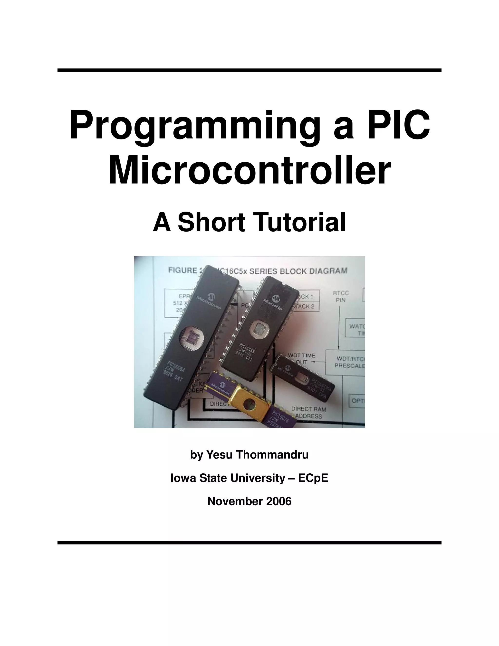
The purpose of this document is to provide a simple, easy to use tutorial on programming PIC
microcontrollers. The tutorial begins with instructions on selecting a specific PIC and ends with
directions for breadboarding the microcontroller.
1.2 Document Conventions
In this document different styles of text and visuals are used to help the reader separate different
types of information. General description text will be in this format, size 11 italicized Arial.
Pseudo-code or source code will be written in multi-color, size 10 Courier New font as in the
following example:
#include <stdio.h>
void main(int argc, char *argv[])
{
printf("Star Wars!n”);
return;
}
Buttons and menu items will be in standard Arial text such as Button with the first letter underlined.
Important notes and pieces of information will appear in normal text in shaded boxes as in the
following example:
NOTE: I think Darth Vader would win in a fight against Boba Fett!
1.3 Intended Audience and Reading Suggestions
The intended audience of this document is students in the Department of Electrical and Computer
Engineering enrolled in EE/CprE 491 or 492 Senior Design. This document can also be used by
any student or individual who wishes to learn the basics of how to program a PIC microcontroller.
There are a number of suggested readings for any users of this document. The following books
are suggested for specific PIC programming tasks:
Introduction to microelectronic systems: the PIC 16F84 microcontroller by Martin Bates.
PIC microcontroller: an intro to software and hardware interfacing by Han-Way Huang.
The PIC microcontroller: your personal introductory course by John Morton.
PIC microcontroller project book by John Lovine.
Programming and customizing the PIC microcontroller by Myke Predko.
The quintessential PIC microcontroller by Sid Katzen.
NOTE: In my experience most of software in these books is written in Assembly and are thus not
useful to students wishing to program in a high-level programming language.](https://image.slidesharecdn.com/tutorialdec0604print24-131108102209-phpapp02/85/Tutorial-dec0604-print24-Programming-a-PIC-4-320.jpg)
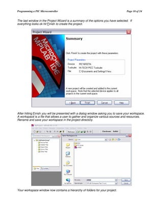
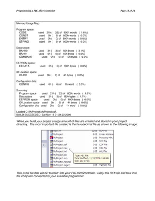

This document provides a tutorial on programming PIC microcontrollers. It discusses choosing a PIC, using the MPLab IDE, writing code in C, and compiling and loading software onto the PIC. The tutorial explains the basic process of selecting a PIC, writing a simple blinking LED program in C, using MPLab to compile and build the project, and describes how to set the configuration bits and burn the hex file to the PIC. It provides helpful tips and notes to guide the reader through programming a PIC microcontroller.


![Pic microcontroller [autosaved] [autosaved]](https://cdn.slidesharecdn.com/ss_thumbnails/picmicrocontrollerautosavedautosaved-120427093459-phpapp02-thumbnail.jpg?width=640&height=640&fit=bounds)