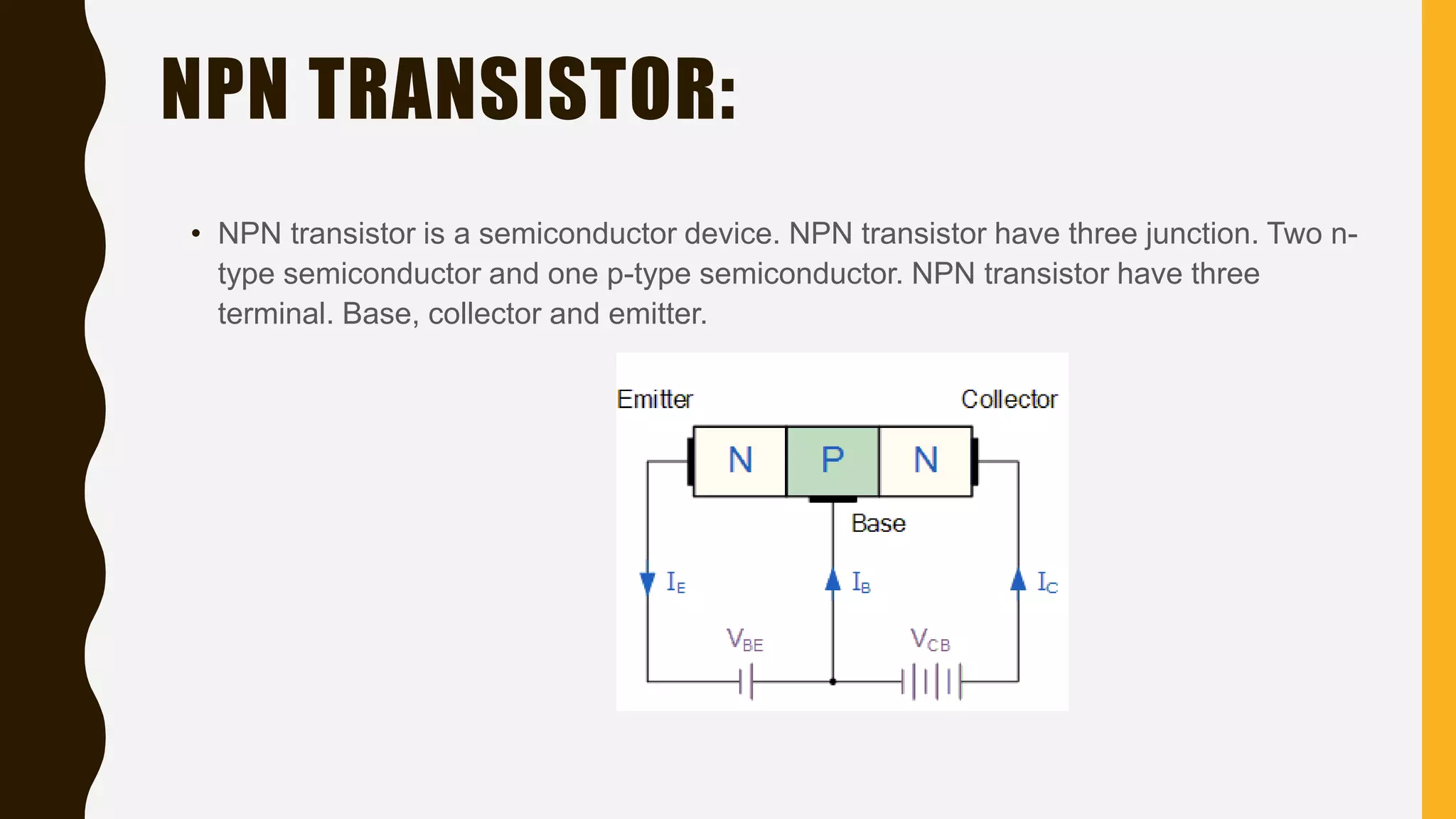
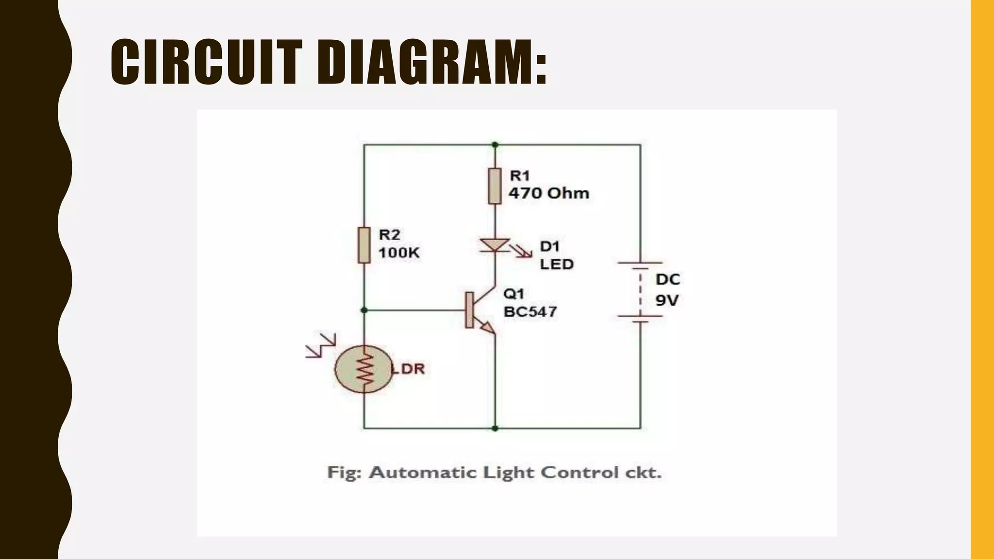
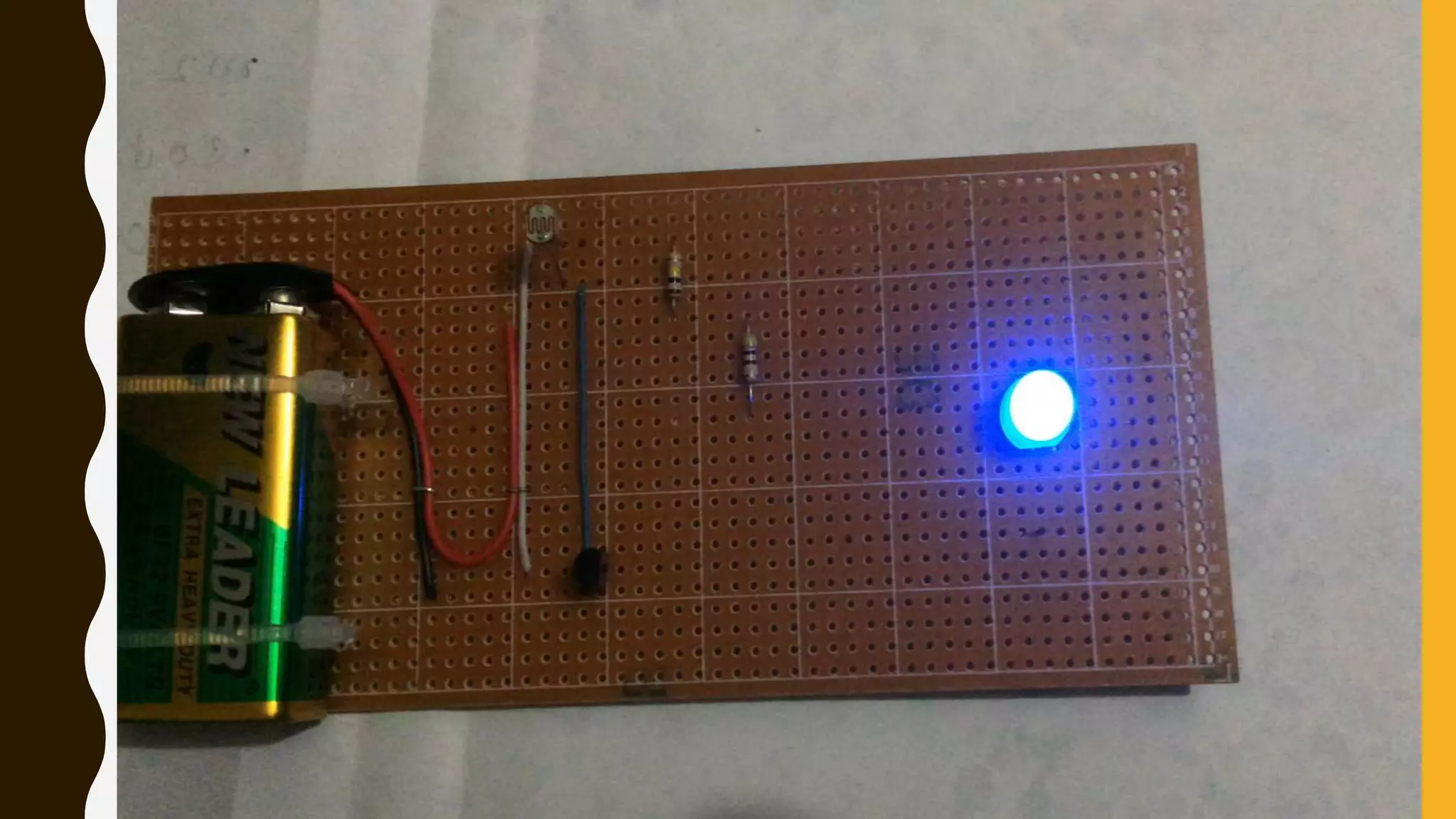
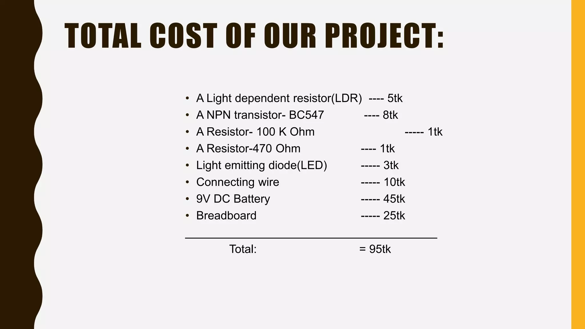
W E L C O M E T O O U R
P R E S E N TAT I O N
Automatic Light Control Using LDR
• Circuit diagram.
• Equipment list with brief.
• Working process.
• Real time video of project.
• Application.
• Advantage.
• Disadvantage.
• Project Cost.
CONTENT:
CIRCUIT DIAGRAM:
EQUIPMENT
• A Light dependent resistor(LDR)
• A NPN transistor- BC547
• A Resistor- 100 K Ohm
• A Resistor-470 Ohm
• Light emitting diode(LED)
• Connecting wires- Use single-core plastic-coated wire
• 9V DC Battery
• Breadboard
LDR:
• What is a Light Dependent?
• LDR is a semiconductor device. When light fall on LDR, LDR acts high resistance and
when dark fall on LDR, acts low resistance.
LED LIGHT:
• What is the LED light?
• A light-emitting diode (LED) is a semiconductor device. LED have two junction. One
p-junction and another n-junction. P-type connect with positive side of battery and N-
type connect with negative side of battery.
NPN TRANSISTOR:
• NPN transistor is a semiconductor device. NPN transistor have three junction. Two n-
type semiconductor and one p-type semiconductor. NPN transistor have three
terminal. Base, collector and emitter.
BREADBOARD, BATTERY, WIRE:
WORKING PROCESS:
• LDR have two side. One side connect with transistor base terminal and another
side connect with transistor emitter terminal.
• R2 100k resistor connect one side connect base terminal and another side
connect with R1 470Ohm resistor.
• R1 resistor have tow side. One side connect with R2 and battery positive
side. And another side connect with positive side of LED.
• A D1 LED diode one side connect with R2 resistor and another side connect
with transistor collector terminal.
• Transistor base terminal connect with LDR and R2 resistor. Collector
connect with LED negative side. And emitter terminal connect with LDR and
battery negative side.
• Battery positive side connect with R1 resistor. And negative side connect with
transistor emitter terminal.
CIRCUIT DIAGRAM:
APPLICATION
• Road Light Control.
• Lamp post.
• Home Security Light Control.
• CC Camera (Night Mode).
• Mobile Phone Tower Signal Light.
ADVANTAGE
• When electricity is gone light is on and when electricity is come light is
off at home.
• This circuit save time.
• It save Power.
• It help to Smart Life.
• Low maintenance.
• Automatic control.
DISADVANTAGE
•Sometime it problem in Cloud Weather.
•Continuously clear dust on the LDR, after few days.
• A Light dependent resistor(LDR) ---- 5tk
• A NPN transistor- BC547 ---- 8tk
• A Resistor- 100 K Ohm ----- 1tk
• A Resistor-470 Ohm ---- 1tk
• Light emitting diode(LED) ----- 3tk
• Connecting wire ----- 10tk
• 9V DC Battery ----- 45tk
• Breadboard ----- 25tk
_______________________________________
Total: = 95tk
TOTAL COST OF OUR PROJECT:
REFERENCE:
http://www.buildcircuit.com
http://www.edgefxkits.com/
http://www.electroschematics.com/
http://www.electronics-project-design.com/
THANK YOU.

Automatic light control Using LDR

  • 1.
    W E LC O M E T O O U R P R E S E N TAT I O N
  • 2.
  • 3.
    • Circuit diagram. •Equipment list with brief. • Working process. • Real time video of project. • Application. • Advantage. • Disadvantage. • Project Cost. CONTENT:
  • 4.
  • 5.
    EQUIPMENT • A Lightdependent resistor(LDR) • A NPN transistor- BC547 • A Resistor- 100 K Ohm • A Resistor-470 Ohm • Light emitting diode(LED) • Connecting wires- Use single-core plastic-coated wire • 9V DC Battery • Breadboard
  • 6.
    LDR: • What isa Light Dependent? • LDR is a semiconductor device. When light fall on LDR, LDR acts high resistance and when dark fall on LDR, acts low resistance.
  • 7.
    LED LIGHT: • Whatis the LED light? • A light-emitting diode (LED) is a semiconductor device. LED have two junction. One p-junction and another n-junction. P-type connect with positive side of battery and N- type connect with negative side of battery.
  • 8.
    NPN TRANSISTOR: • NPNtransistor is a semiconductor device. NPN transistor have three junction. Two n- type semiconductor and one p-type semiconductor. NPN transistor have three terminal. Base, collector and emitter.
  • 9.
  • 10.
    WORKING PROCESS: • LDRhave two side. One side connect with transistor base terminal and another side connect with transistor emitter terminal. • R2 100k resistor connect one side connect base terminal and another side connect with R1 470Ohm resistor. • R1 resistor have tow side. One side connect with R2 and battery positive side. And another side connect with positive side of LED. • A D1 LED diode one side connect with R2 resistor and another side connect with transistor collector terminal. • Transistor base terminal connect with LDR and R2 resistor. Collector connect with LED negative side. And emitter terminal connect with LDR and battery negative side. • Battery positive side connect with R1 resistor. And negative side connect with transistor emitter terminal.
  • 11.
  • 13.
    APPLICATION • Road LightControl. • Lamp post. • Home Security Light Control. • CC Camera (Night Mode). • Mobile Phone Tower Signal Light.
  • 14.
    ADVANTAGE • When electricityis gone light is on and when electricity is come light is off at home. • This circuit save time. • It save Power. • It help to Smart Life. • Low maintenance. • Automatic control.
  • 15.
    DISADVANTAGE •Sometime it problemin Cloud Weather. •Continuously clear dust on the LDR, after few days.
  • 16.
    • A Lightdependent resistor(LDR) ---- 5tk • A NPN transistor- BC547 ---- 8tk • A Resistor- 100 K Ohm ----- 1tk • A Resistor-470 Ohm ---- 1tk • Light emitting diode(LED) ----- 3tk • Connecting wire ----- 10tk • 9V DC Battery ----- 45tk • Breadboard ----- 25tk _______________________________________ Total: = 95tk TOTAL COST OF OUR PROJECT:
  • 17.
  • 18.