Download to read offline
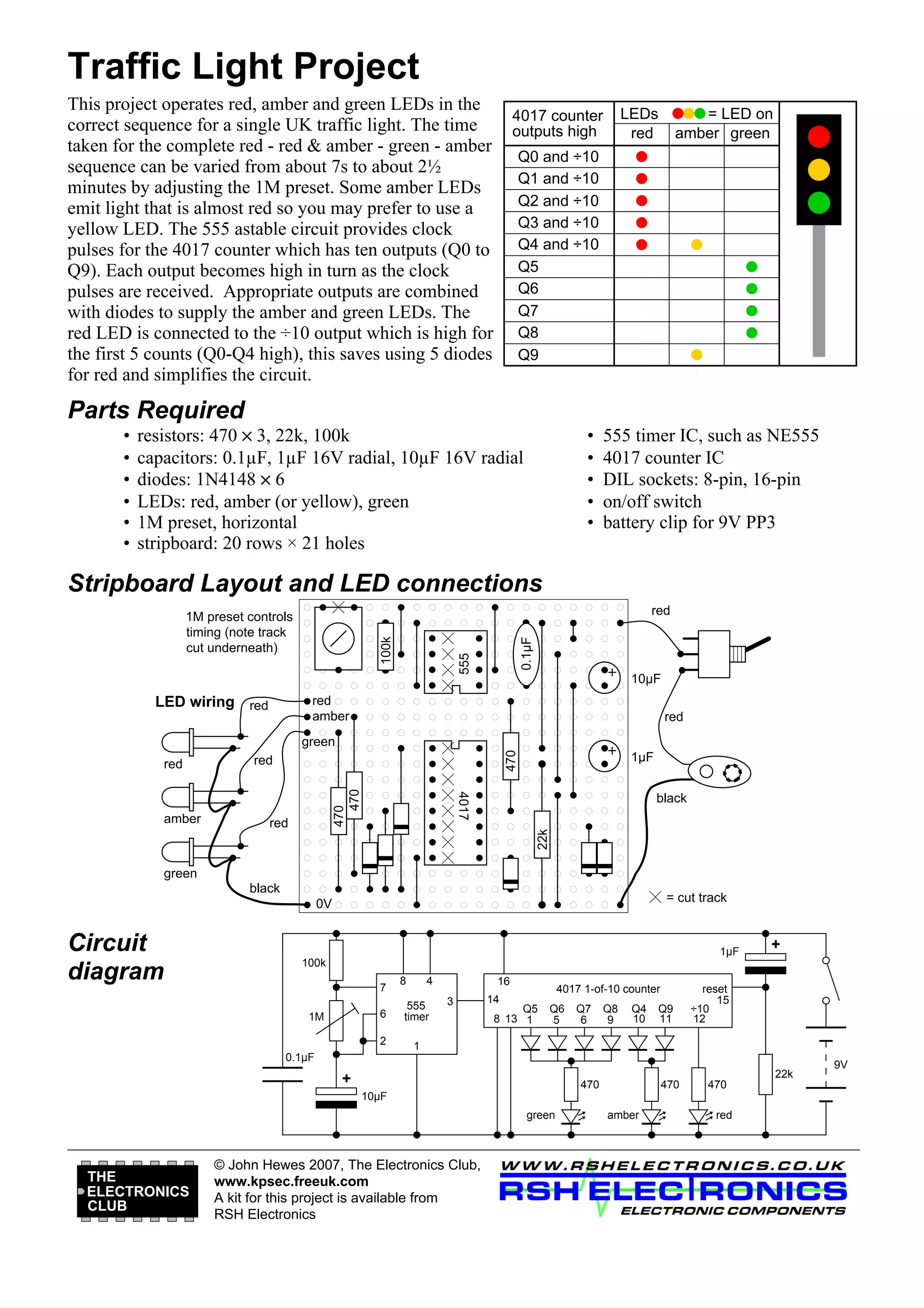

This project builds a traffic light circuit that sequences red, amber, and green LEDs to mimic a single UK traffic light. A 555 timer chip and 4017 counter chip are used to generate the timing signals. The 1M preset can adjust the full cycle time from 7 seconds to 2.5 minutes. The circuit diagram, parts list, stripboard layout, and LED connections are provided to construct the traffic light circuit.


![Vibe Coding vs. Spec-Driven Development [Free Meetup]](https://cdn.slidesharecdn.com/ss_thumbnails/vibecodingvsspecdrivendevelopment-251209105622-43f455e7-thumbnail.jpg?width=640&height=640&fit=bounds)


