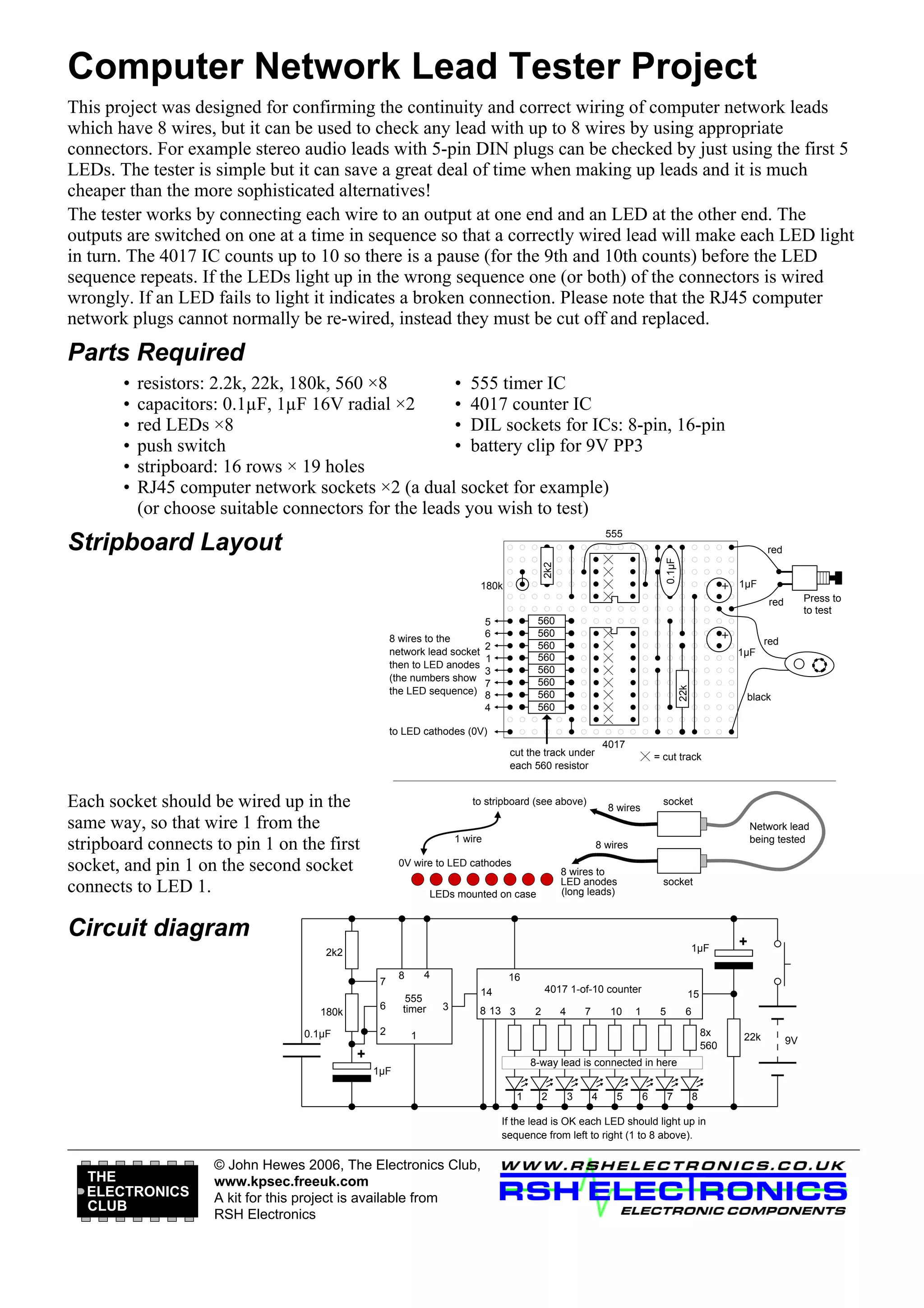
Computer Network Lead Tester Project
This project was designed for confirming the continuity and correct wiring of computer network leads
which have 8 wires, but it can be used to check any lead with up to 8 wires by using appropriate
connectors. For example stereo audio leads with 5-pin DIN plugs can be checked by just using the first 5
LEDs. The tester is simple but it can save a great deal of time when making up leads and it is much
cheaper than the more sophisticated alternatives!
The tester works by connecting each wire to an output at one end and an LED at the other end. The
outputs are switched on one at a time in sequence so that a correctly wired lead will make each LED light
in turn. The 4017 IC counts up to 10 so there is a pause (for the 9th and 10th counts) before the LED
sequence repeats. If the LEDs light up in the wrong sequence one (or both) of the connectors is wired
wrongly. If an LED fails to light it indicates a broken connection. Please note that the RJ45 computer
network plugs cannot normally be re-wired, instead they must be cut off and replaced.

Parts Required
•
•
•
•
•
•

resistors: 2.2k, 22k, 180k, 560 ×8
• 555 timer IC
capacitors: 0.1µF, 1µF 16V radial ×2
• 4017 counter IC
red LEDs ×8
• DIL sockets for ICs: 8-pin, 16-pin
push switch
• battery clip for 9V PP3
stripboard: 16 rows × 19 holes
RJ45 computer network sockets ×2 (a dual socket for example)
(or choose suitable connectors for the leads you wish to test)
555

Stripboard Layout
2k2

0.1µF

red

180k

1µF
Press to
to test

red
560
560
560
560
560
560
560
560

red
1µF

22k

5
6
2
1
3
7
8
4

8 wires to the
network lead socket
then to LED anodes
(the numbers show
the LED sequence)

black

to LED cathodes (0V)
4017

cut the track under
each 560 resistor

Each socket should be wired up in the
same way, so that wire 1 from the
stripboard connects to pin 1 on the first
socket, and pin 1 on the second socket
connects to LED 1.

= cut track

to stripboard (see above)

1 wire

socket

8 wires

Network lead
being tested

8 wires

0V wire to LED cathodes

8 wires to
LED anodes
(long leads)

LEDs mounted on case

socket

Circuit diagram
1µF

2k2
7

4

8

6
2

180k
0.1µF

555
timer

16
4017 1-of-10 counter

14

15

1

3

8 13 3

2

4

7

10

1

5

6
8x
560

+

8-way lead is connected in here

1µF
1

2

3

4

5

6

7

8

If the lead is OK each LED should light up in
sequence from left to right (1 to 8 above).

THE
ELECTRONICS
CLUB

+

© John Hewes 2006, The Electronics Club,
www.kpsec.freeuk.com
A kit for this project is available from
RSH Electronics

22k

9V

Circuit For Continuity Tester

  • 1.
    Computer Network LeadTester Project This project was designed for confirming the continuity and correct wiring of computer network leads which have 8 wires, but it can be used to check any lead with up to 8 wires by using appropriate connectors. For example stereo audio leads with 5-pin DIN plugs can be checked by just using the first 5 LEDs. The tester is simple but it can save a great deal of time when making up leads and it is much cheaper than the more sophisticated alternatives! The tester works by connecting each wire to an output at one end and an LED at the other end. The outputs are switched on one at a time in sequence so that a correctly wired lead will make each LED light in turn. The 4017 IC counts up to 10 so there is a pause (for the 9th and 10th counts) before the LED sequence repeats. If the LEDs light up in the wrong sequence one (or both) of the connectors is wired wrongly. If an LED fails to light it indicates a broken connection. Please note that the RJ45 computer network plugs cannot normally be re-wired, instead they must be cut off and replaced. Parts Required • • • • • • resistors: 2.2k, 22k, 180k, 560 ×8 • 555 timer IC capacitors: 0.1µF, 1µF 16V radial ×2 • 4017 counter IC red LEDs ×8 • DIL sockets for ICs: 8-pin, 16-pin push switch • battery clip for 9V PP3 stripboard: 16 rows × 19 holes RJ45 computer network sockets ×2 (a dual socket for example) (or choose suitable connectors for the leads you wish to test) 555 Stripboard Layout 2k2 0.1µF red 180k 1µF Press to to test red 560 560 560 560 560 560 560 560 red 1µF 22k 5 6 2 1 3 7 8 4 8 wires to the network lead socket then to LED anodes (the numbers show the LED sequence) black to LED cathodes (0V) 4017 cut the track under each 560 resistor Each socket should be wired up in the same way, so that wire 1 from the stripboard connects to pin 1 on the first socket, and pin 1 on the second socket connects to LED 1. = cut track to stripboard (see above) 1 wire socket 8 wires Network lead being tested 8 wires 0V wire to LED cathodes 8 wires to LED anodes (long leads) LEDs mounted on case socket Circuit diagram 1µF 2k2 7 4 8 6 2 180k 0.1µF 555 timer 16 4017 1-of-10 counter 14 15 1 3 8 13 3 2 4 7 10 1 5 6 8x 560 + 8-way lead is connected in here 1µF 1 2 3 4 5 6 7 8 If the lead is OK each LED should light up in sequence from left to right (1 to 8 above). THE ELECTRONICS CLUB + © John Hewes 2006, The Electronics Club, www.kpsec.freeuk.com A kit for this project is available from RSH Electronics 22k 9V