Download to read offline
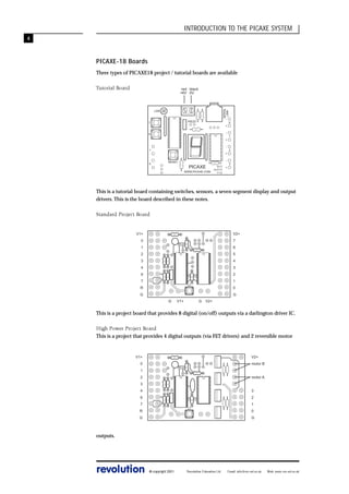

The document provides an introduction to the PICAXE microcontroller system. It describes the PICAXE as a simple to program microcontroller that uses a BASIC language. The system includes PICAXE chips, a programming editor software, and serial download cable. It can be used to replace electronic components and simplify product design. Sample programs are included to turn an output on and off to flash a light.


