Downloaded 2,629 times

![9
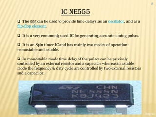
IC NE555 [PIN DIAGRAM]
PIN 1 “GROUND” low level (0 V)
PIN 2 “TRIGGER” Voltage below 1/3 Vcc to trigger the pulse
PIN 3 “OUT” Pulsating output
Aug-12](https://image.slidesharecdn.com/miniproject-120831111515-phpapp01/85/water-level-indicator-alarm-9-320.jpg)
![15
BATTERY[12V]
It is a collection of one or more electrochemical cells in which
stored chemical energy is converted into electrical energy.
The principles of operation haven‟t changed much since the time
of Volta.
Each cell consists of two half cells connected in series through an
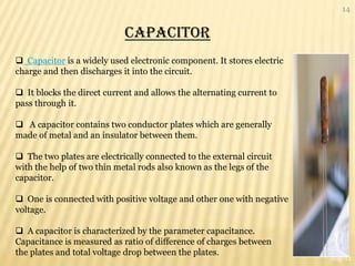
electrolytic solution.
One half cell houses the Anode to which the positive ions migrate
from the Electrolyte and the other houses the Cathode to which
the negative ones drift.
The two cells are may be connected via a semi permeable
membranous structure allowing ions to flow but not the mixing of
electrolytes as in the case of most primary cells or in the same
solution as in secondary cells.
Aug-12](https://image.slidesharecdn.com/miniproject-120831111515-phpapp01/85/water-level-indicator-alarm-15-320.jpg)


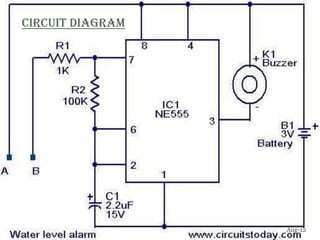
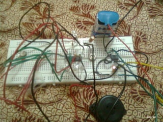
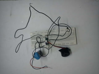
This document describes the design of a water level alarm indicator circuit. The circuit uses an NE555 timer IC, resistors, capacitors, a buzzer, and a 12V battery. It functions as an astable multivibrator where the operating frequency depends on the water level between two probes - no water means no connection and no beeping, water connecting the probes completes the circuit and causes beeping. The circuit provides a simple and low-cost way to audibly alert when water in a tank reaches a certain level.


![5G Explained! A High Level Overview [Introduction]](https://cdn.slidesharecdn.com/ss_thumbnails/5gexplainedahighleveloverview-260119165306-cc137a3e-thumbnail.jpg?width=640&height=640&fit=bounds)


