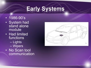
- Early automotive control systems in the 1980s-1990s had standalone modules with limited functions like lights and wipers and no communication abilities.
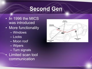
- In the late 1990s and early 2000s, automakers introduced controller area networks (CAN buses) to link multiple electronic control modules and enable features like power windows and communication with scan tools.
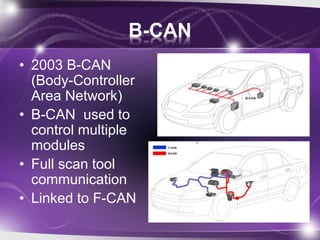
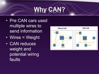
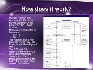
- Honda's 2003 B-CAN network was its body-controller area network that controlled multiple body modules and had full scan tool communication. It was also linked to the engine-focused F-CAN network. CAN networks reduced wiring complexity and weight compared to individual wiring harnesses.