Download as PDF, PPTX
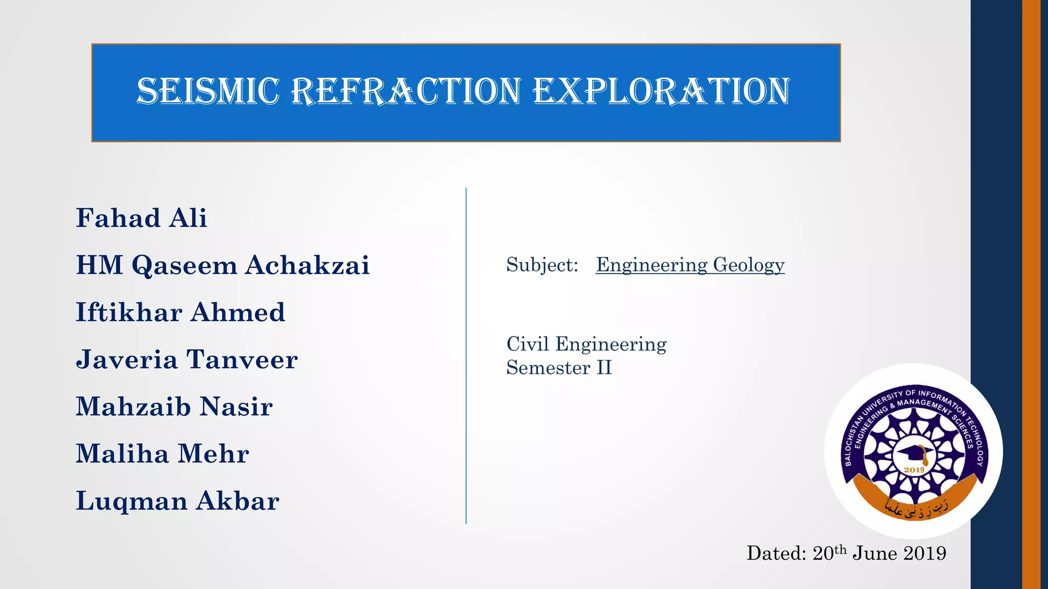


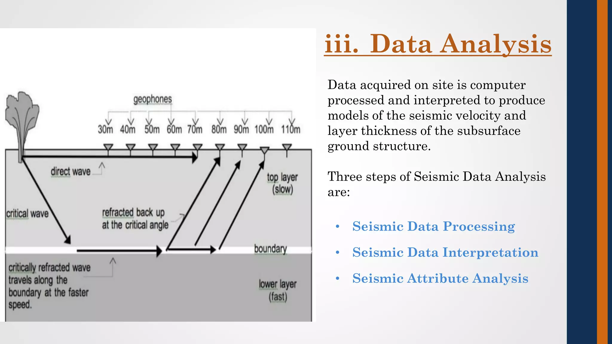
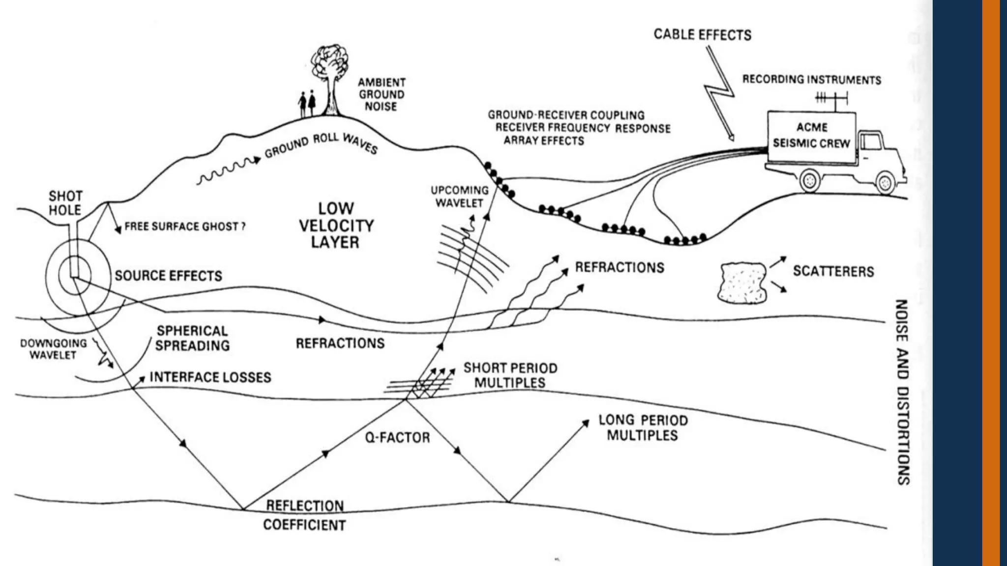


The document provides a detailed overview of seismic refraction methods used in engineering geology and geophysics for subsurface exploration, highlighting techniques such as seismic wave generation and data interpretation. It describes key processes involved in seismic data analysis, including deconvolution, stacking, and migration, as well as assumptions and precautions necessary for accurate survey results. Applications of the methods include mapping geological structures, determining bedrock depth, and identifying resources like hydrocarbons and groundwater.