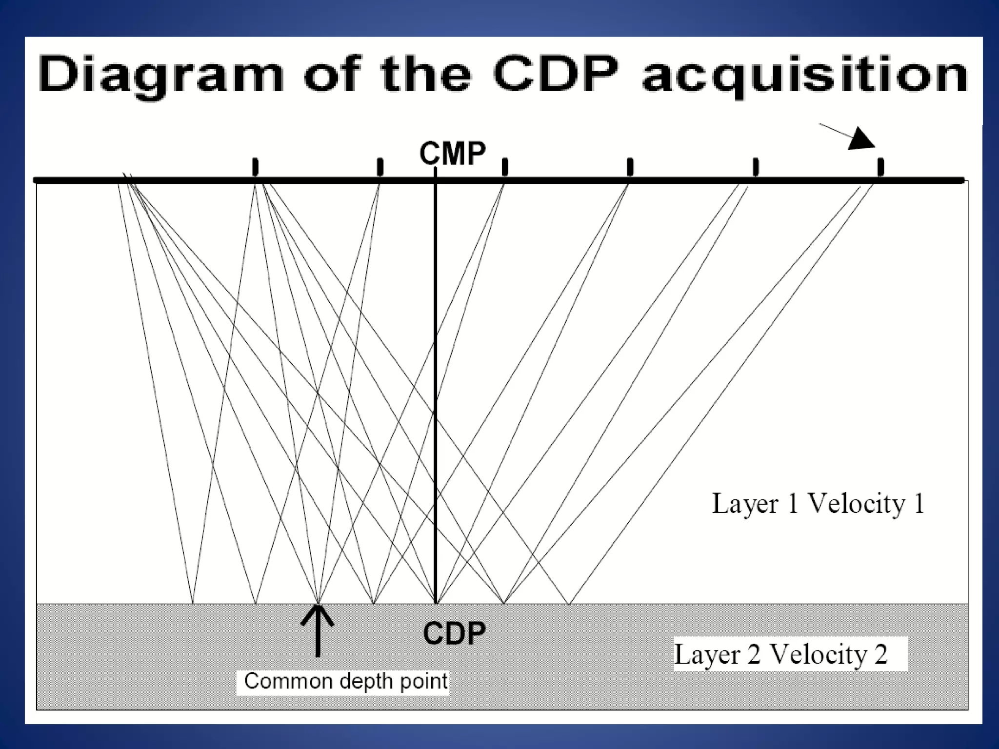
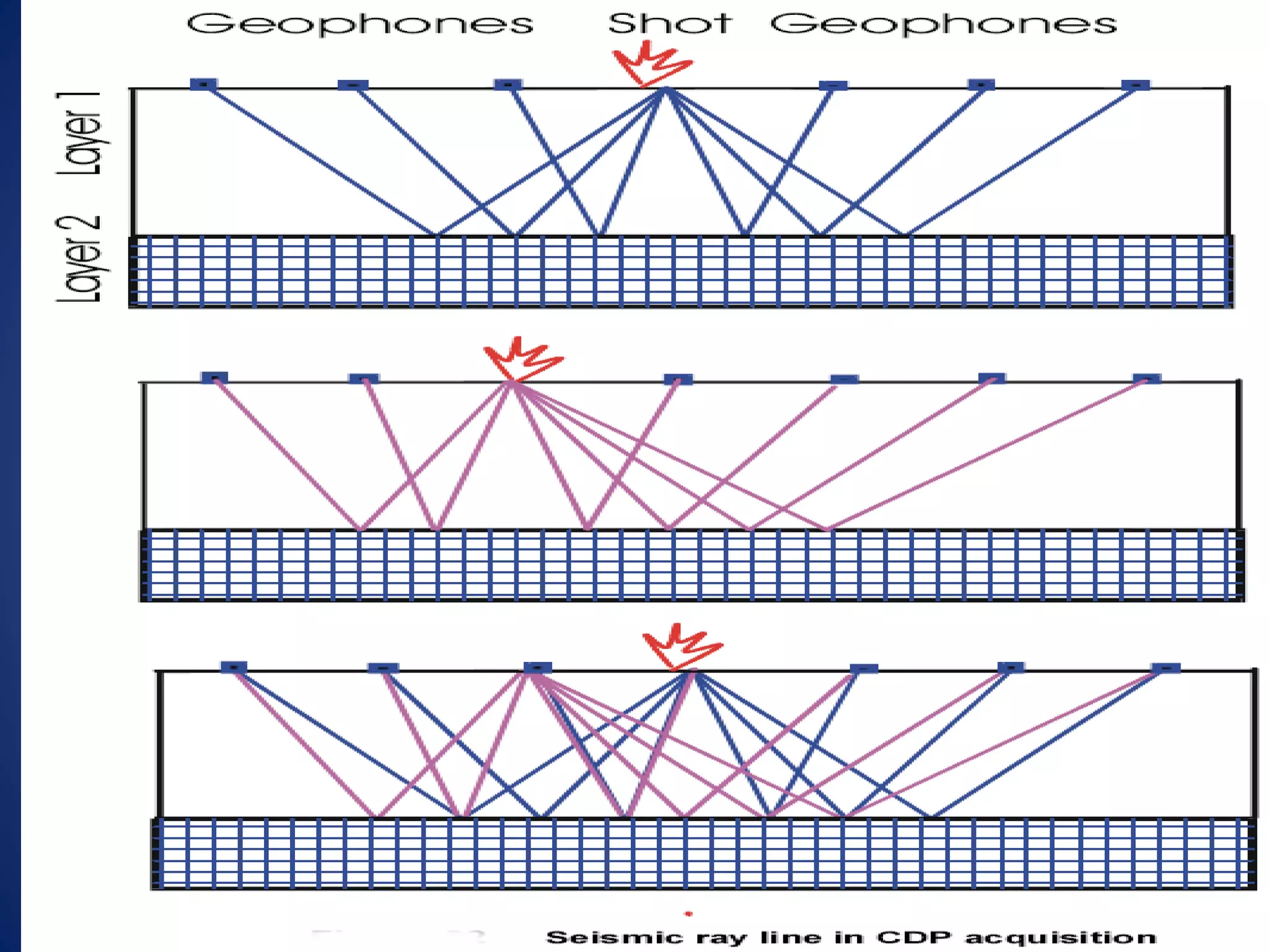
SlideShare a Scribd company logo
Introduction
to Seismic
Method:
• Measurement of seismic-wave travel time is one of the most
common geophysical method.
• Seismic exploration is divided into refraction and reflection
surveys, depending on whether the predominant portion of
the seismic waves’ travel is horizontal or vertical.
• Refraction seismic surveys are used in engineering geophysics
and petroleum exploration.
• Seismic reflection surveys, on the other hand, detect
boundaries between different kinds of rocks; this detection
assists in the mapping of geological structures.
• Seismic energy is detected on land by using devices called
geophones, which react to on-site ground motions.
SEISMIC METHOD
SEISMIC SURVEY
• OBJECTIVES
• PREPARATION & PLANNING
• PARAMETER SELECTION
• INSTRUMENTS
• FIELD OPERATION
OBJECTIVES
REGIONAL EXPLORATORY INVESTIGATIONS
• Delineation of structural and stratigraphic anomalies
FIELD DEVELOPMENT
• To mark suitable locations for field development and for reservoir
studies
PROSPECT DELINEATION
• To mark the depth of prospective horizon and trap
closures
PREPARATION
AVAILABLE BUDGET & TIME
AVAILABLE DATA
Geological Data
Geophysical Data
Other Information
PLANNING & DESIGNING
1. ACQUISITION PARAMETERS
2. BID INVITATION
a. Minimum Offset b. Maximum Offset
c. Source Interval
e. No. of Channels
d. Receiver Interval
g. Source (Dynamite or Vibroseis)
RECEIVER AND SOURCE PARAMETER SELECTION
• SPREAD TYPE
• RECEIVER LAYOUT
• SOURCE TYPE
INSTRUMENT FOR SEISMIC SURVEYING
1. Geophone.
2. Seismic Cable.
3. Seismograph.
4. Energy Source.
5. Seismic Crew.
Weight drop
Dynamite
SOURCE TYPE
Vibroseis
Hammer
DYNAMITE
• SHOT HOLE DEPTH
• CHARGE SIZE
• SHOT POINT INTERVAL
• NUMBER OF HOLES
• SOURCE ARRAY PATTERN
SP Interval
Hole Depth
Charge Size
PARAMETERS:
•The blast of explosives produces a very
strong energy,
•Placing of the explosives to the bottom of
a hole from 1 to 35 meters,)and the energy
is better distributed.
•In order to make the holes, a hammer
perforator, an auger or drilling rig is used.
•In the sand, a simple metallic tube is very
efficient.
•In some desert regions, where the drilling
is impossible, explosives can be suspended
and exploded in the air about 1.5 m from
the ground
•This method, very noisy & dangerous
VIBROSEIS
FIELD PROCEDURE
• Planting geophone along a straight line and detonating.
• Generating seismic waves by detonating explosives on one end of a line.
• Recording seismograph.
• Picking 1st arrivals.
• plotting of data to determine V1V2h1
Trimble Man Pack - 4700 GPS
• GPS used by the Survey Crew
for locating the Source & Receiver
Points of the Seismic lines, carried
on their shoulders
External Batteries and Receiver
• Its is connected with two external
batteries and a receiver which receives
the signal from the satellite.
Shot Points Receiver Points
• After locating the points, the crew mark the places of source
and receiver points finally marking a seismic line
Source Points with red paint Receiver Points with white paint
Drilling Jackhammer
• Drilling Crew uses Jackhammers
for shallow holes
Man Portable Drilling Rig
• For deep holes, Man Portable
Drilling Rigs are used
Dynamite Stick for Deep Shots
• After drilling shot holes dynamite is
loaded in them, using dynamite sticks
Detonator
• Detonators are placed in the dynamite
stick, used to initiate the blasting of
dynamite
• Lowering of Charge in a Drilled Hole
with detonator in them
• Hole is loaded and filled with Sand
• Loading is done and place is marked
Geophone Stings
Takeout Point of a Takeout Cable
• This crew first of all layout the
Geophones on the seismic lines
as spread.
• These geophones are connected
to each other by the Takeout Cable
CABLE & GEOPHONE
Link cableGeophone string
LAYOUT(FRONT CREW)
CABLE LAYOUT
GEOPHONE PLANTATION
ROAD CROSSING
LINE
SOURCE
RECEIVER
Station Unit Box
• Takeout cable is then connected to
Station Unit Box
Crossing Station Unit Box
• All the Station Unit Box is further
connected with one Crossing Station
Unit Box (of an array)
• Then yellow cable called Jumper Cable
is finally connected to Recording Truck
through which all the information goes
into it
RECORDER
CABLE PLUG IN THE RECORDER
FROM SPREAD
Color Line Monitor
Recorder
Tape Driver
• Monitor on which the Observer control
all the activities on a seismic line
• The recorder which records all the data
coming through cables
• The tape driver records all the data
on the magnetic tapes or cartridges
Camera
Seismic Source Synchronizer
• The thermal plotter used to make a hard
copy of the recorded data
• Device which synchronizes the blaster.
Before shooting, recorder presses ARM
button to charge the detonators, at the
same time the blaster operator presses
the ARM button in the blaster
• Then recorder presses GO button to
blast the dynamite
Portable recording system
SEISOMOGRAPH
Blaster
• Bag carried by the shooting crew is called
The Blaster, it works in coordination with
the Seismic Source Synchronizer
• “Blast view” on seismic
line
A recorded result of shot point after the blast
SEISOMOGRAM
A recorded result of shot point after the blast
SEISOMOGRAM
• After all the shots are recorded every thing is wounded
• The data is send to the Operator Company
• The place is restored by the Green Team and inspected by
the Client Company
• Then Operator Company sends data to DGPC
SPREAD GEOMETRY
The most common recording type consists to send seismic
waves from one shot point and to record reflected waves
with many (48, 96 or more) geophones regularly disposed
on the ground along a seismic cable.
The CDP is the reflection point in depth, then CMP is the
midpoint on the ground between shot and a geophone.
With a switch (roll-along switch), the observer can
"displaces" the recording geophones along the line with a
constant number of actives geophones (24, 48 or more).
The aim of this process is to add the travels having a
reflective common point, in order to improve the signal /
noise ratio. With 48 active geophones, there are 24 travels
adding on a common reflector (Fold 24).
Basic Spreads
The shot or the vibration point can be situated:
• At the extremity of the active geophones (End shot)
• At the center of the geophones. (Split spread shot)
• At a certain distance (offset) of first geophone
The last geometry allows to have a long distance of offset,
The second is more adapted if the reflectors are tilted.
NOISE
Noise is the information on the seismic
record which one does not wish to use.
TYPES OF NOISE:
1. Random Noise or Incoherent Noise
2. Coherent Noise
RANDOM NOISE OR IN COHERENT NOISE
It is the seismic energy that does not align up from trace to
trace or record to record on seismic record It displays no
systematic pattern.
This noise is uncorrectable.
We can overcome random noises by recording more than
one traces from the same location.
Sources of Random Noise:
i. Wind Noise
ii. Water Flow Noise
iii. Small Movement With in the Earth
iv. Local Noise
v. Bad Geophone Noise
COHERENT NOISE
It is seismic energy which aligns from trace to trace or record to record on
seismic record.
• Often, it is very similar to the signal and usually more difficult to
overcome than the incoherent/random noise.
• By examining the patterns of coherent noise, we can
devise field procedures to reduce it.
Source size and source depth , Electric Filtering, Receiver Arrays,
Source Arrays, Deconvolution and Editing and Muting.
Sources Of Coherent Noise:
i. Multiple Reflections
ii. Direct Arrivals and Refracted Waves
iii. Diffraction Events
iv. Ground Roll
• Head waves are always the first events seen on a record.
• They are linear and often very visible and strong.
• Sometimes they can disappear with large offset.
• Many geophysicists try to remove head wave using
•surgical mute,
•FK filtering
•adapted NMO stretch mute value,
• but in some case, uppermost reflection and refraction
can be very close and difficult to distinguish.
Refracted Waves
In Seismic reflection survey the refracted events
comes as first arrival.
Ground Roll
Ground rolls are Rayleigh waves which
appear as second arrival on seismic section.
• Surface waves (Rayleigh, Love) primarily Rayleigh
are
– low velocity,
– low frequency signal,
– With relatively higher amplitude seen below shots.
They override the useful reflections.
• They can be reduced using
– frequency filtering
– FK filtering.
Diffracted Events
At faults and some unconformities diffracted waves
are generated on seismic section.
• The seismic reflection takes an interest essentially to the P compression
waves, in the setting of seismic studies for the geo-technical;
• the recording of the S waves can to prove out to be useful for the
shearing modules calculation.
• In knowing the velocity of the P waves and S, it is possible of calculating
the Poisson’s ratio:
Refraction Methods
Advantages Disadvantages
Refraction observations generally
employ fewer source and receiver
locations and are thus relatively
cheap to acquire.
Little processing is done on refraction
observations with the exception of
filtering to help in the process of
picking the arrival times of the
initial ground motion.
Because such a small portion of the
recorded ground motion is used,
developing models and
interpretations is no more difficult
than our previous efforts with
other geophysical surveys.
Refraction seismic observations require
relatively large source-receiver offsets
(distances between the source and
where the ground motion is recorded,
the receiver).
Refraction seismic only works if the speed at
which motions propagate through the
Earth increases with depth.
Refraction seismic observations are generally
interpreted in terms of layers. These
layers can have dip and topography.
Refraction seismic observations only use the
arrival time of the initial ground motion
at different distances from the source
(i.e., offsets).
A model for the subsurface is constructed by
attempting to reproduce the observed
arrival times.
Refraction Survey
Advantages
– Amplitude of refractor are large.
– Best for exploration of shallow structures.
– Easy to process and interpret.
Disadvantages
– Exploration for deeper structures is difficult because of large XCrit distance,
– Blind to low velocity layers.
Reflection Methods
Advantages Disadvantages
Reflection seismic observations are
collected at small source-receiver
offsets.
Reflection seismic methods can work
no matter how the speed at which
motions propagate through the
Earth varies with depth.
Reflection seismic observations can be
more readily interpreted in terms
of complex geology.
Reflection seismic observations use the
entire reflected wave field (i.e., the
time-history of ground motion at
different distances between the
source and the receiver).
The subsurface is directly imaged from
the acquired observations
Because many source and receiver locations must
be used to produce meaningful images of the
Earth's subsurface, reflection seismic
observations can be expensive to acquire.
Reflection seismic processing can be very
computer intensive, requiring sophisticated
computer hardware and a relatively high-
level of expertise. Thus, the processing of
reflection seismic observations is relatively
expensive.
Because of the overwhelming amount of data
collected, the possible complications imposed
by the propagation of ground motion through
a complex earth, and the complications
imposed by some of the necessary
simplifications required by the data
processing schemes, interpretations of the
reflection seismic observations require more
sophistication and knowledge of the process.
Seismic Reflection Survey
Advantages
– Geophone spread needed is relatively shorter.
– Not blind to low velocity layers. Since acoustic impedance exist for
every layer.
– Convenient for deeper exploration.
Disadvantages
– Difficulty in recognizing reflected waves.
– Small amplitude.
– Obscured by overlapping refracted and surface waves.

More Related Content

What's hot

Presentation on geophysical methods
Presentation on geophysical methodsPresentation on geophysical methods
Presentation on geophysical methods
Engr Andrew A. Onoja MNSE, MNICE, COREN, MNIM, MICE
 
Seismic Refraction Surveying
Seismic Refraction SurveyingSeismic Refraction Surveying
Seismic Refraction SurveyingAli Osman Öncel
 
Ambiguity in Geophysics
Ambiguity in GeophysicsAmbiguity in Geophysics
Ambiguity in Geophysics
knigh7
 
Geophysical methods
Geophysical methodsGeophysical methods
Geophysical methods
Fands-llc
 
Geophysical methods brief summary
Geophysical methods brief summaryGeophysical methods brief summary
Geophysical methods brief summary
Jyoti Khatiwada
 
Geological mapping
Geological mappingGeological mapping
Geological mapping
Pramoda Raj
 
Gravity Method
Gravity MethodGravity Method
Gravity Method
Tahsin Islam Ornee
 
Well logging
Well loggingWell logging
Well logging
University of Kerala
 
Electrical method
Electrical methodElectrical method
Electrical method
mahmudulhassan123
 
Introduction to Seismic Method
Introduction to Seismic MethodIntroduction to Seismic Method
Introduction to Seismic MethodŞarlatan Avcısı
 
Geophysical prospecting
Geophysical prospecting Geophysical prospecting
Geophysical prospecting Spondan Bora
 
Resistivity Survey
Resistivity SurveyResistivity Survey
Resistivity Survey
Amit K. Mishra
 
Gravity Method | Geophysics | Geology
Gravity Method | Geophysics | GeologyGravity Method | Geophysics | Geology
Gravity Method | Geophysics | Geology
Geology Department | Faculty of Natural Science
 
Radioactive Survey
Radioactive SurveyRadioactive Survey
Radioactive Survey
Thendral Kumaresan
 
Geophysics. GRAVIMETERY METHOD
Geophysics.  GRAVIMETERY METHOD Geophysics.  GRAVIMETERY METHOD
Geophysics. GRAVIMETERY METHOD fatemeh vejdani
 
Sequence stratigraphy and its applications
Sequence stratigraphy and its applicationsSequence stratigraphy and its applications
Sequence stratigraphy and its applications
Pramoda Raj
 
Geophysical survey
Geophysical surveyGeophysical survey
Geophysical survey
Abdul Jabbar
 
Seismic Reflection
Seismic ReflectionSeismic Reflection
Seismic Reflection
Sevar Dilkhaz
 
Gravity & magnetic methods in geology
Gravity & magnetic methods in geologyGravity & magnetic methods in geology
Gravity & magnetic methods in geology
Md Asif Hasan
 
Induced polarization method (electrical survey)
Induced polarization method (electrical survey)Induced polarization method (electrical survey)
Induced polarization method (electrical survey)
SudhanKumarSubedi
 

What's hot (20)

Presentation on geophysical methods
Presentation on geophysical methodsPresentation on geophysical methods
Presentation on geophysical methods
 
Seismic Refraction Surveying
Seismic Refraction SurveyingSeismic Refraction Surveying
Seismic Refraction Surveying
 
Ambiguity in Geophysics
Ambiguity in GeophysicsAmbiguity in Geophysics
Ambiguity in Geophysics
 
Geophysical methods
Geophysical methodsGeophysical methods
Geophysical methods
 
Geophysical methods brief summary
Geophysical methods brief summaryGeophysical methods brief summary
Geophysical methods brief summary
 
Geological mapping
Geological mappingGeological mapping
Geological mapping
 
Gravity Method
Gravity MethodGravity Method
Gravity Method
 
Well logging
Well loggingWell logging
Well logging
 
Electrical method
Electrical methodElectrical method
Electrical method
 
Introduction to Seismic Method
Introduction to Seismic MethodIntroduction to Seismic Method
Introduction to Seismic Method
 
Geophysical prospecting
Geophysical prospecting Geophysical prospecting
Geophysical prospecting
 
Resistivity Survey
Resistivity SurveyResistivity Survey
Resistivity Survey
 
Gravity Method | Geophysics | Geology
Gravity Method | Geophysics | GeologyGravity Method | Geophysics | Geology
Gravity Method | Geophysics | Geology
 
Radioactive Survey
Radioactive SurveyRadioactive Survey
Radioactive Survey
 
Geophysics. GRAVIMETERY METHOD
Geophysics.  GRAVIMETERY METHOD Geophysics.  GRAVIMETERY METHOD
Geophysics. GRAVIMETERY METHOD
 
Sequence stratigraphy and its applications
Sequence stratigraphy and its applicationsSequence stratigraphy and its applications
Sequence stratigraphy and its applications
 
Geophysical survey
Geophysical surveyGeophysical survey
Geophysical survey
 
Seismic Reflection
Seismic ReflectionSeismic Reflection
Seismic Reflection
 
Gravity & magnetic methods in geology
Gravity & magnetic methods in geologyGravity & magnetic methods in geology
Gravity & magnetic methods in geology
 
Induced polarization method (electrical survey)
Induced polarization method (electrical survey)Induced polarization method (electrical survey)
Induced polarization method (electrical survey)
 

Similar to Introduction to Seismic Method

New introduction to seismic method
New introduction to seismic method New introduction to seismic method
New introduction to seismic method
University of Azad Jammu & Kashmir
 
Lec (remote sensing).pptx
Lec (remote sensing).pptxLec (remote sensing).pptx
Lec (remote sensing).pptx
SarfrazFaiz
 
Seismic refractionsurveying r4a
Seismic refractionsurveying r4aSeismic refractionsurveying r4a
Seismic refractionsurveying r4a
Alina Arshad
 
Introduction to seismic interpretation
Introduction to seismic interpretationIntroduction to seismic interpretation
Introduction to seismic interpretation
Amir I. Abdelaziz
 
Landslide monitoring systems & techniques
Landslide monitoring systems & techniquesLandslide monitoring systems & techniques
Landslide monitoring systems & techniques
maneeb
 
At seismic survey
At seismic surveyAt seismic survey
At seismic survey
Asrar Hussain
 
Morocco2022_LocationProblem_Bondar.pptx
Morocco2022_LocationProblem_Bondar.pptxMorocco2022_LocationProblem_Bondar.pptx
Morocco2022_LocationProblem_Bondar.pptx
ouchenibrahim1
 
Remote sensing in Civil Engineering
Remote sensing in Civil EngineeringRemote sensing in Civil Engineering
Remote sensing in Civil Engineering
Manishkumar Dubey
 
Seismic waves geometry
Seismic waves geometrySeismic waves geometry
Seismic waves geometry
Gamal Eldien Tarek
 
GNSS Observation (4)
GNSS Observation (4)GNSS Observation (4)
GNSS Observation (4)
NopphawanTamkuan
 
Seismic Refraction Test
Seismic Refraction TestSeismic Refraction Test
Seismic Refraction Test
Maliha Mehr
 
Well logging
Well loggingWell logging
Well logging
PE Mahmoud Jad
 
01 - Overview of Geophysical Methods.pptx
01 - Overview of Geophysical Methods.pptx01 - Overview of Geophysical Methods.pptx
01 - Overview of Geophysical Methods.pptx
Agnikulakshatriyasan
 
Biases and Receivers (3)
Biases and Receivers (3)Biases and Receivers (3)
Biases and Receivers (3)
NopphawanTamkuan
 
JohnHintonUCTPoster
JohnHintonUCTPosterJohnHintonUCTPoster
JohnHintonUCTPosterjohnhinton92
 
Remote sensing technology and applications
Remote  sensing technology and applicationsRemote  sensing technology and applications
Remote sensing technology and applications
Shyam Sundar Roy
 
Microwave Link Design - PTP Transmission
Microwave  Link Design - PTP TransmissionMicrowave  Link Design - PTP Transmission
Microwave Link Design - PTP Transmission
Mohamed Sewailam
 
TOTAL EARTH SOLUTIONS - PETROLEUM EXPLORATION SERVICES
TOTAL EARTH SOLUTIONS - PETROLEUM EXPLORATION SERVICESTOTAL EARTH SOLUTIONS - PETROLEUM EXPLORATION SERVICES
TOTAL EARTH SOLUTIONS - PETROLEUM EXPLORATION SERVICES
Brett Johnson
 
Seismic interpretation
Seismic interpretationSeismic interpretation
Seismic interpretation
PrernaBSRawat
 

Similar to Introduction to Seismic Method (20)

New introduction to seismic method
New introduction to seismic method New introduction to seismic method
New introduction to seismic method
 
Lec (remote sensing).pptx
Lec (remote sensing).pptxLec (remote sensing).pptx
Lec (remote sensing).pptx
 
Seismic refractionsurveying r4a
Seismic refractionsurveying r4aSeismic refractionsurveying r4a
Seismic refractionsurveying r4a
 
Introduction to seismic interpretation
Introduction to seismic interpretationIntroduction to seismic interpretation
Introduction to seismic interpretation
 
Landslide monitoring systems & techniques
Landslide monitoring systems & techniquesLandslide monitoring systems & techniques
Landslide monitoring systems & techniques
 
At seismic survey
At seismic surveyAt seismic survey
At seismic survey
 
Morocco2022_LocationProblem_Bondar.pptx
Morocco2022_LocationProblem_Bondar.pptxMorocco2022_LocationProblem_Bondar.pptx
Morocco2022_LocationProblem_Bondar.pptx
 
Remote sensing in Civil Engineering
Remote sensing in Civil EngineeringRemote sensing in Civil Engineering
Remote sensing in Civil Engineering
 
Seismic waves geometry
Seismic waves geometrySeismic waves geometry
Seismic waves geometry
 
GNSS Observation (4)
GNSS Observation (4)GNSS Observation (4)
GNSS Observation (4)
 
Seismic Refraction Test
Seismic Refraction TestSeismic Refraction Test
Seismic Refraction Test
 
Well logging
Well loggingWell logging
Well logging
 
01 - Overview of Geophysical Methods.pptx
01 - Overview of Geophysical Methods.pptx01 - Overview of Geophysical Methods.pptx
01 - Overview of Geophysical Methods.pptx
 
Biases and Receivers (3)
Biases and Receivers (3)Biases and Receivers (3)
Biases and Receivers (3)
 
JohnHintonUCTPoster
JohnHintonUCTPosterJohnHintonUCTPoster
JohnHintonUCTPoster
 
Remote sensing technology and applications
Remote  sensing technology and applicationsRemote  sensing technology and applications
Remote sensing technology and applications
 
Microwave Link Design - PTP Transmission
Microwave  Link Design - PTP TransmissionMicrowave  Link Design - PTP Transmission
Microwave Link Design - PTP Transmission
 
Subsidence in coal mines
Subsidence in coal minesSubsidence in coal mines
Subsidence in coal mines
 
TOTAL EARTH SOLUTIONS - PETROLEUM EXPLORATION SERVICES
TOTAL EARTH SOLUTIONS - PETROLEUM EXPLORATION SERVICESTOTAL EARTH SOLUTIONS - PETROLEUM EXPLORATION SERVICES
TOTAL EARTH SOLUTIONS - PETROLEUM EXPLORATION SERVICES
 
Seismic interpretation
Seismic interpretationSeismic interpretation
Seismic interpretation
 

More from Ahmed Younhais Tariq

Joints (Geology)
Joints (Geology)Joints (Geology)
Joints (Geology)
Ahmed Younhais Tariq
 
Rock Mass Classification
Rock Mass ClassificationRock Mass Classification
Rock Mass Classification
Ahmed Younhais Tariq
 
Technical report writing
Technical report writingTechnical report writing
Technical report writing
Ahmed Younhais Tariq
 
Earthquake
EarthquakeEarthquake

More from Ahmed Younhais Tariq (6)

Joints (Geology)
Joints (Geology)Joints (Geology)
Joints (Geology)
 
Rock Mass Classification
Rock Mass ClassificationRock Mass Classification
Rock Mass Classification
 
Technical report writing
Technical report writingTechnical report writing
Technical report writing
 
Earthquake
EarthquakeEarthquake
Earthquake
 
Gem Stone and its Properties
Gem Stone and its PropertiesGem Stone and its Properties
Gem Stone and its Properties
 
Coal... Uploaded by Ahmed G
Coal... Uploaded by Ahmed GCoal... Uploaded by Ahmed G
Coal... Uploaded by Ahmed G
 

Recently uploaded

How to Create Map Views in the Odoo 17 ERP
How to Create Map Views in the Odoo 17 ERPHow to Create Map Views in the Odoo 17 ERP
How to Create Map Views in the Odoo 17 ERP
Celine George
 
Additional Benefits for Employee Website.pdf
Additional Benefits for Employee Website.pdfAdditional Benefits for Employee Website.pdf
Additional Benefits for Employee Website.pdf
joachimlavalley1
 
Basic phrases for greeting and assisting costumers
Basic phrases for greeting and assisting costumersBasic phrases for greeting and assisting costumers
Basic phrases for greeting and assisting costumers
PedroFerreira53928
 
The approach at University of Liverpool.pptx
The approach at University of Liverpool.pptxThe approach at University of Liverpool.pptx
The approach at University of Liverpool.pptx
Jisc
 
special B.ed 2nd year old paper_20240531.pdf
special B.ed 2nd year old paper_20240531.pdfspecial B.ed 2nd year old paper_20240531.pdf
special B.ed 2nd year old paper_20240531.pdf
Special education needs
 
How to Make a Field invisible in Odoo 17
How to Make a Field invisible in Odoo 17How to Make a Field invisible in Odoo 17
How to Make a Field invisible in Odoo 17
Celine George
 
aaaaaaaaaaaaaaaaaaaaaaaaaaaaaaaaaaaaaaaaa
aaaaaaaaaaaaaaaaaaaaaaaaaaaaaaaaaaaaaaaaaaaaaaaaaaaaaaaaaaaaaaaaaaaaaaaaaaaaaaaaaa
aaaaaaaaaaaaaaaaaaaaaaaaaaaaaaaaaaaaaaaaa
siemaillard
 
1.4 modern child centered education - mahatma gandhi-2.pptx
1.4 modern child centered education - mahatma gandhi-2.pptx1.4 modern child centered education - mahatma gandhi-2.pptx
1.4 modern child centered education - mahatma gandhi-2.pptx
JosvitaDsouza2
 
How libraries can support authors with open access requirements for UKRI fund...
How libraries can support authors with open access requirements for UKRI fund...How libraries can support authors with open access requirements for UKRI fund...
How libraries can support authors with open access requirements for UKRI fund...
Jisc
 
Home assignment II on Spectroscopy 2024 Answers.pdf
Home assignment II on Spectroscopy 2024 Answers.pdfHome assignment II on Spectroscopy 2024 Answers.pdf
Home assignment II on Spectroscopy 2024 Answers.pdf
Tamralipta Mahavidyalaya
 
Fish and Chips - have they had their chips
Fish and Chips - have they had their chipsFish and Chips - have they had their chips
Fish and Chips - have they had their chips
GeoBlogs
 
Operation Blue Star - Saka Neela Tara
Operation Blue Star   -  Saka Neela TaraOperation Blue Star   -  Saka Neela Tara
Operation Blue Star - Saka Neela Tara
Balvir Singh
 
Thesis Statement for students diagnonsed withADHD.ppt
Thesis Statement for students diagnonsed withADHD.pptThesis Statement for students diagnonsed withADHD.ppt
Thesis Statement for students diagnonsed withADHD.ppt
EverAndrsGuerraGuerr
 
Palestine last event orientationfvgnh .pptx
Palestine last event orientationfvgnh .pptxPalestine last event orientationfvgnh .pptx
Palestine last event orientationfvgnh .pptx
RaedMohamed3
 
Ethnobotany and Ethnopharmacology ......
Ethnobotany and Ethnopharmacology ......Ethnobotany and Ethnopharmacology ......
Ethnobotany and Ethnopharmacology ......
Ashokrao Mane college of Pharmacy Peth-Vadgaon
 
PART A. Introduction to Costumer Service
PART A. Introduction to Costumer ServicePART A. Introduction to Costumer Service
PART A. Introduction to Costumer Service
PedroFerreira53928
 
Synthetic Fiber Construction in lab .pptx
Synthetic Fiber Construction in lab .pptxSynthetic Fiber Construction in lab .pptx
Synthetic Fiber Construction in lab .pptx
Pavel ( NSTU)
 
CLASS 11 CBSE B.St Project AIDS TO TRADE - INSURANCE
CLASS 11 CBSE B.St Project AIDS TO TRADE - INSURANCECLASS 11 CBSE B.St Project AIDS TO TRADE - INSURANCE
CLASS 11 CBSE B.St Project AIDS TO TRADE - INSURANCE
BhavyaRajput3
 
Phrasal Verbs.XXXXXXXXXXXXXXXXXXXXXXXXXX
Phrasal Verbs.XXXXXXXXXXXXXXXXXXXXXXXXXXPhrasal Verbs.XXXXXXXXXXXXXXXXXXXXXXXXXX
Phrasal Verbs.XXXXXXXXXXXXXXXXXXXXXXXXXX
MIRIAMSALINAS13
 
Sha'Carri Richardson Presentation 202345
Sha'Carri Richardson Presentation 202345Sha'Carri Richardson Presentation 202345
Sha'Carri Richardson Presentation 202345
beazzy04
 

Recently uploaded (20)

How to Create Map Views in the Odoo 17 ERP
How to Create Map Views in the Odoo 17 ERPHow to Create Map Views in the Odoo 17 ERP
How to Create Map Views in the Odoo 17 ERP
 
Additional Benefits for Employee Website.pdf
Additional Benefits for Employee Website.pdfAdditional Benefits for Employee Website.pdf
Additional Benefits for Employee Website.pdf
 
Basic phrases for greeting and assisting costumers
Basic phrases for greeting and assisting costumersBasic phrases for greeting and assisting costumers
Basic phrases for greeting and assisting costumers
 
The approach at University of Liverpool.pptx
The approach at University of Liverpool.pptxThe approach at University of Liverpool.pptx
The approach at University of Liverpool.pptx
 
special B.ed 2nd year old paper_20240531.pdf
special B.ed 2nd year old paper_20240531.pdfspecial B.ed 2nd year old paper_20240531.pdf
special B.ed 2nd year old paper_20240531.pdf
 
How to Make a Field invisible in Odoo 17
How to Make a Field invisible in Odoo 17How to Make a Field invisible in Odoo 17
How to Make a Field invisible in Odoo 17
 
aaaaaaaaaaaaaaaaaaaaaaaaaaaaaaaaaaaaaaaaa
aaaaaaaaaaaaaaaaaaaaaaaaaaaaaaaaaaaaaaaaaaaaaaaaaaaaaaaaaaaaaaaaaaaaaaaaaaaaaaaaaa
aaaaaaaaaaaaaaaaaaaaaaaaaaaaaaaaaaaaaaaaa
 
1.4 modern child centered education - mahatma gandhi-2.pptx
1.4 modern child centered education - mahatma gandhi-2.pptx1.4 modern child centered education - mahatma gandhi-2.pptx
1.4 modern child centered education - mahatma gandhi-2.pptx
 
How libraries can support authors with open access requirements for UKRI fund...
How libraries can support authors with open access requirements for UKRI fund...How libraries can support authors with open access requirements for UKRI fund...
How libraries can support authors with open access requirements for UKRI fund...
 
Home assignment II on Spectroscopy 2024 Answers.pdf
Home assignment II on Spectroscopy 2024 Answers.pdfHome assignment II on Spectroscopy 2024 Answers.pdf
Home assignment II on Spectroscopy 2024 Answers.pdf
 
Fish and Chips - have they had their chips
Fish and Chips - have they had their chipsFish and Chips - have they had their chips
Fish and Chips - have they had their chips
 
Operation Blue Star - Saka Neela Tara
Operation Blue Star   -  Saka Neela TaraOperation Blue Star   -  Saka Neela Tara
Operation Blue Star - Saka Neela Tara
 
Thesis Statement for students diagnonsed withADHD.ppt
Thesis Statement for students diagnonsed withADHD.pptThesis Statement for students diagnonsed withADHD.ppt
Thesis Statement for students diagnonsed withADHD.ppt
 
Palestine last event orientationfvgnh .pptx
Palestine last event orientationfvgnh .pptxPalestine last event orientationfvgnh .pptx
Palestine last event orientationfvgnh .pptx
 
Ethnobotany and Ethnopharmacology ......
Ethnobotany and Ethnopharmacology ......Ethnobotany and Ethnopharmacology ......
Ethnobotany and Ethnopharmacology ......
 
PART A. Introduction to Costumer Service
PART A. Introduction to Costumer ServicePART A. Introduction to Costumer Service
PART A. Introduction to Costumer Service
 
Synthetic Fiber Construction in lab .pptx
Synthetic Fiber Construction in lab .pptxSynthetic Fiber Construction in lab .pptx
Synthetic Fiber Construction in lab .pptx
 
CLASS 11 CBSE B.St Project AIDS TO TRADE - INSURANCE
CLASS 11 CBSE B.St Project AIDS TO TRADE - INSURANCECLASS 11 CBSE B.St Project AIDS TO TRADE - INSURANCE
CLASS 11 CBSE B.St Project AIDS TO TRADE - INSURANCE
 
Phrasal Verbs.XXXXXXXXXXXXXXXXXXXXXXXXXX
Phrasal Verbs.XXXXXXXXXXXXXXXXXXXXXXXXXXPhrasal Verbs.XXXXXXXXXXXXXXXXXXXXXXXXXX
Phrasal Verbs.XXXXXXXXXXXXXXXXXXXXXXXXXX
 
Sha'Carri Richardson Presentation 202345
Sha'Carri Richardson Presentation 202345Sha'Carri Richardson Presentation 202345
Sha'Carri Richardson Presentation 202345
 

Introduction to Seismic Method

  • 2. • Measurement of seismic-wave travel time is one of the most common geophysical method. • Seismic exploration is divided into refraction and reflection surveys, depending on whether the predominant portion of the seismic waves’ travel is horizontal or vertical. • Refraction seismic surveys are used in engineering geophysics and petroleum exploration. • Seismic reflection surveys, on the other hand, detect boundaries between different kinds of rocks; this detection assists in the mapping of geological structures. • Seismic energy is detected on land by using devices called geophones, which react to on-site ground motions. SEISMIC METHOD
  • 3. SEISMIC SURVEY • OBJECTIVES • PREPARATION & PLANNING • PARAMETER SELECTION • INSTRUMENTS • FIELD OPERATION
  • 4. OBJECTIVES REGIONAL EXPLORATORY INVESTIGATIONS • Delineation of structural and stratigraphic anomalies FIELD DEVELOPMENT • To mark suitable locations for field development and for reservoir studies PROSPECT DELINEATION • To mark the depth of prospective horizon and trap closures
  • 5. PREPARATION AVAILABLE BUDGET & TIME AVAILABLE DATA Geological Data Geophysical Data Other Information
  • 6. PLANNING & DESIGNING 1. ACQUISITION PARAMETERS 2. BID INVITATION a. Minimum Offset b. Maximum Offset c. Source Interval e. No. of Channels d. Receiver Interval g. Source (Dynamite or Vibroseis)
  • 7. RECEIVER AND SOURCE PARAMETER SELECTION • SPREAD TYPE • RECEIVER LAYOUT • SOURCE TYPE
  • 8. INSTRUMENT FOR SEISMIC SURVEYING 1. Geophone. 2. Seismic Cable. 3. Seismograph. 4. Energy Source. 5. Seismic Crew.
  • 10. DYNAMITE • SHOT HOLE DEPTH • CHARGE SIZE • SHOT POINT INTERVAL • NUMBER OF HOLES • SOURCE ARRAY PATTERN SP Interval Hole Depth Charge Size PARAMETERS:
  • 11. •The blast of explosives produces a very strong energy, •Placing of the explosives to the bottom of a hole from 1 to 35 meters,)and the energy is better distributed. •In order to make the holes, a hammer perforator, an auger or drilling rig is used. •In the sand, a simple metallic tube is very efficient. •In some desert regions, where the drilling is impossible, explosives can be suspended and exploded in the air about 1.5 m from the ground •This method, very noisy & dangerous
  • 13.
  • 14.
  • 15.
  • 16.
  • 17. FIELD PROCEDURE • Planting geophone along a straight line and detonating. • Generating seismic waves by detonating explosives on one end of a line. • Recording seismograph. • Picking 1st arrivals. • plotting of data to determine V1V2h1
  • 18. Trimble Man Pack - 4700 GPS • GPS used by the Survey Crew for locating the Source & Receiver Points of the Seismic lines, carried on their shoulders External Batteries and Receiver • Its is connected with two external batteries and a receiver which receives the signal from the satellite.
  • 19. Shot Points Receiver Points • After locating the points, the crew mark the places of source and receiver points finally marking a seismic line Source Points with red paint Receiver Points with white paint
  • 20. Drilling Jackhammer • Drilling Crew uses Jackhammers for shallow holes Man Portable Drilling Rig • For deep holes, Man Portable Drilling Rigs are used
  • 21. Dynamite Stick for Deep Shots • After drilling shot holes dynamite is loaded in them, using dynamite sticks Detonator • Detonators are placed in the dynamite stick, used to initiate the blasting of dynamite
  • 22. • Lowering of Charge in a Drilled Hole with detonator in them • Hole is loaded and filled with Sand • Loading is done and place is marked
  • 23. Geophone Stings Takeout Point of a Takeout Cable • This crew first of all layout the Geophones on the seismic lines as spread. • These geophones are connected to each other by the Takeout Cable
  • 24. CABLE & GEOPHONE Link cableGeophone string
  • 30. Station Unit Box • Takeout cable is then connected to Station Unit Box Crossing Station Unit Box • All the Station Unit Box is further connected with one Crossing Station Unit Box (of an array) • Then yellow cable called Jumper Cable is finally connected to Recording Truck through which all the information goes into it
  • 32. CABLE PLUG IN THE RECORDER FROM SPREAD
  • 33. Color Line Monitor Recorder Tape Driver • Monitor on which the Observer control all the activities on a seismic line • The recorder which records all the data coming through cables • The tape driver records all the data on the magnetic tapes or cartridges
  • 34. Camera Seismic Source Synchronizer • The thermal plotter used to make a hard copy of the recorded data • Device which synchronizes the blaster. Before shooting, recorder presses ARM button to charge the detonators, at the same time the blaster operator presses the ARM button in the blaster • Then recorder presses GO button to blast the dynamite
  • 36. Blaster • Bag carried by the shooting crew is called The Blaster, it works in coordination with the Seismic Source Synchronizer • “Blast view” on seismic line
  • 37. A recorded result of shot point after the blast SEISOMOGRAM
  • 38. A recorded result of shot point after the blast SEISOMOGRAM
  • 39. • After all the shots are recorded every thing is wounded • The data is send to the Operator Company • The place is restored by the Green Team and inspected by the Client Company • Then Operator Company sends data to DGPC
  • 40.
  • 41.
  • 42.
  • 43.
  • 44.
  • 45.
  • 46. SPREAD GEOMETRY The most common recording type consists to send seismic waves from one shot point and to record reflected waves with many (48, 96 or more) geophones regularly disposed on the ground along a seismic cable. The CDP is the reflection point in depth, then CMP is the midpoint on the ground between shot and a geophone. With a switch (roll-along switch), the observer can "displaces" the recording geophones along the line with a constant number of actives geophones (24, 48 or more). The aim of this process is to add the travels having a reflective common point, in order to improve the signal / noise ratio. With 48 active geophones, there are 24 travels adding on a common reflector (Fold 24).
  • 48.
  • 49. The shot or the vibration point can be situated: • At the extremity of the active geophones (End shot) • At the center of the geophones. (Split spread shot) • At a certain distance (offset) of first geophone The last geometry allows to have a long distance of offset, The second is more adapted if the reflectors are tilted.
  • 50.
  • 51.
  • 52.
  • 53.
  • 54.
  • 55.
  • 56.
  • 57.
  • 58.
  • 59. NOISE Noise is the information on the seismic record which one does not wish to use. TYPES OF NOISE: 1. Random Noise or Incoherent Noise 2. Coherent Noise
  • 60. RANDOM NOISE OR IN COHERENT NOISE It is the seismic energy that does not align up from trace to trace or record to record on seismic record It displays no systematic pattern. This noise is uncorrectable. We can overcome random noises by recording more than one traces from the same location. Sources of Random Noise: i. Wind Noise ii. Water Flow Noise iii. Small Movement With in the Earth iv. Local Noise v. Bad Geophone Noise
  • 61. COHERENT NOISE It is seismic energy which aligns from trace to trace or record to record on seismic record. • Often, it is very similar to the signal and usually more difficult to overcome than the incoherent/random noise. • By examining the patterns of coherent noise, we can devise field procedures to reduce it. Source size and source depth , Electric Filtering, Receiver Arrays, Source Arrays, Deconvolution and Editing and Muting. Sources Of Coherent Noise: i. Multiple Reflections ii. Direct Arrivals and Refracted Waves iii. Diffraction Events iv. Ground Roll
  • 62.
  • 63. • Head waves are always the first events seen on a record. • They are linear and often very visible and strong. • Sometimes they can disappear with large offset. • Many geophysicists try to remove head wave using •surgical mute, •FK filtering •adapted NMO stretch mute value, • but in some case, uppermost reflection and refraction can be very close and difficult to distinguish.
  • 64. Refracted Waves In Seismic reflection survey the refracted events comes as first arrival.
  • 65. Ground Roll Ground rolls are Rayleigh waves which appear as second arrival on seismic section.
  • 66. • Surface waves (Rayleigh, Love) primarily Rayleigh are – low velocity, – low frequency signal, – With relatively higher amplitude seen below shots. They override the useful reflections. • They can be reduced using – frequency filtering – FK filtering.
  • 67. Diffracted Events At faults and some unconformities diffracted waves are generated on seismic section.
  • 68.
  • 69.
  • 70. • The seismic reflection takes an interest essentially to the P compression waves, in the setting of seismic studies for the geo-technical; • the recording of the S waves can to prove out to be useful for the shearing modules calculation. • In knowing the velocity of the P waves and S, it is possible of calculating the Poisson’s ratio:
  • 71. Refraction Methods Advantages Disadvantages Refraction observations generally employ fewer source and receiver locations and are thus relatively cheap to acquire. Little processing is done on refraction observations with the exception of filtering to help in the process of picking the arrival times of the initial ground motion. Because such a small portion of the recorded ground motion is used, developing models and interpretations is no more difficult than our previous efforts with other geophysical surveys. Refraction seismic observations require relatively large source-receiver offsets (distances between the source and where the ground motion is recorded, the receiver). Refraction seismic only works if the speed at which motions propagate through the Earth increases with depth. Refraction seismic observations are generally interpreted in terms of layers. These layers can have dip and topography. Refraction seismic observations only use the arrival time of the initial ground motion at different distances from the source (i.e., offsets). A model for the subsurface is constructed by attempting to reproduce the observed arrival times.
  • 72. Refraction Survey Advantages – Amplitude of refractor are large. – Best for exploration of shallow structures. – Easy to process and interpret. Disadvantages – Exploration for deeper structures is difficult because of large XCrit distance, – Blind to low velocity layers.
  • 73. Reflection Methods Advantages Disadvantages Reflection seismic observations are collected at small source-receiver offsets. Reflection seismic methods can work no matter how the speed at which motions propagate through the Earth varies with depth. Reflection seismic observations can be more readily interpreted in terms of complex geology. Reflection seismic observations use the entire reflected wave field (i.e., the time-history of ground motion at different distances between the source and the receiver). The subsurface is directly imaged from the acquired observations Because many source and receiver locations must be used to produce meaningful images of the Earth's subsurface, reflection seismic observations can be expensive to acquire. Reflection seismic processing can be very computer intensive, requiring sophisticated computer hardware and a relatively high- level of expertise. Thus, the processing of reflection seismic observations is relatively expensive. Because of the overwhelming amount of data collected, the possible complications imposed by the propagation of ground motion through a complex earth, and the complications imposed by some of the necessary simplifications required by the data processing schemes, interpretations of the reflection seismic observations require more sophistication and knowledge of the process.
  • 74. Seismic Reflection Survey Advantages – Geophone spread needed is relatively shorter. – Not blind to low velocity layers. Since acoustic impedance exist for every layer. – Convenient for deeper exploration. Disadvantages – Difficulty in recognizing reflected waves. – Small amplitude. – Obscured by overlapping refracted and surface waves.