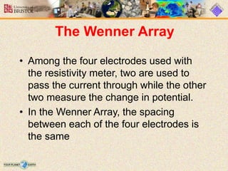
Presentation topic
Electrical resistivity
Method
Presenter:
Salahudin Khursheed
5641
Electric resistivity methods
• Electric resistivity methods are a form of
geophysical surveying that aids in
imaging the subsurface. These methods
utilize differences in electric potential to
identify subsurface material
What is electrical resistance?
• Resistance is an electrical quantity that
measures how the device or material
reduces the electric current flow through
it.
• The resistance is measured in units
of ohms (Ω).
Principle
• Ohms law:
• The law stating that the direct current
flowing in a conductor is directly proportio
nal to the potential difference between its
ends. It is usually formulated as V = I
R, where V is the potential difference, or
voltage, I is the current, and R is the resis
tance of the conductor.
Resistance calculation with
ohm's law
• R=V/I
• R is the resistance of the resistor in
ohms
• V is the voltage drop on the resistor in
volts (V)
• I is the current of the resistor in
amperes (A).
Configuration and electrode
spacing
• The basic setup for a resistivity survey
involves using a resistivity meter and
four electrodes.
• The resistivity meter is a device that
acts as both a voltmeter (measuring V)
and an ammeter (measuring I) and
records resistance values (V/I).
• These resistance values are converted
to apparent resistivity values using the
formula:
• where ρa = apparent resistivity
• k = geometric factor. The geometric
factor varies based on the geometry of
each electrode spacing setup.
The Wenner Array
• Among the four electrodes used with
the resistivity meter, two are used to
pass the current through while the other
two measure the change in potential.
• In the Wenner Array, the spacing
between each of the four electrodes is
the same
The Schlumberger Array
• With the Schlumberger array, only the
outer two electrodes (the electrodes
supplying and receiving the current) are
moved. The advantage of this is that it
is much
• faster because only two electrodes have
to be moved rather than the 4 with the
Wenner array
The Gradient Array
• With the gradient array, the spacing of the
outer two electrodes is kept constant while
the two inner electrodes (the potential
electrodes) are moved
• The spacing between the inner electrodes
is constant but they are moved as a pair in
the space between the outer electrodes and
measure the potential as they go.
METHODS
• Vertical Electric Sounding
• Electric profiling
• Electric Imaging
Vertical Electric Sounding
• VES is one of the more commonly used and
cost effective resistivity survey methods.
Current is moved through the subsurface
from one current electrode to the other and
the potential as the current moves is
recorded. From this information, resistivity
values of various layers is acquired and
layer thickness can be identified.
Electric profiling
• Where VES focuses on determining resistivity
variations on a vertical scale, electric profiling
seeks to determine resistivity variations on a
horizontal scale
• , the electrode spacing is kept constant and
the entire survey is moved along a line or a
"profile" to measure horizontal changes in
resistivity
Electric Imaging
• Both VES and electric profiling are limited to
surveying in one direction. Electric imaging is
able to survey both vertical and horizontal
changes in resistivity.
• This method essentially combines the other two
methods. Electrode spacing is increased and the
survey is moved along a profile in order to
measure both vertical and horizontal resistivity.
Instrumentation
• The basic parts of a resistivity measurement
system include a source of electrical current, a
voltage measuring system, and the cables to
connect these components to the electrodes.
These components have undergone major
modifications over the years to improve the
efficiency of the survey procedure, the quality of
the data, and to increase the depth of
investigation.
• SOURCE:
• The power source for the current is
typically a battery for shallow surveys.
• For deeper surveys where currents of
up to 10 A are used, a petrol/diesel
engine– powered electric generator is
usually used.
• Resistivity meter:
• An instrument used to
carry out resistivity
surveys that usually has
a current transmitter
and voltage measuring
circuitry.
• Multi-core cable:
• A cable with a number of
independent wires.
• Electrode: A conductor planted into the
ground through which current is passed, or
which is used to measure the voltage
caused by the current.
• Metal stakes (Lu and Macnae, 1998) are
commonly used for the current electrodes
as well as the potential electrodes in
resistivity surveys
• For some ground conditions where it is
difficult to insert a stake electrode, flat-base
(or plate) electrodes have been used
Applications
• groundwater detection
• mineral exploration
• waste exploration, oil identification, and
several others.
: Pseudosection created from a resistivity survey near
Phoenix, Arizona. Provided by HGI.

Resistivity method

  • 1.
  • 2.
  • 3.
    Electric resistivity methods •Electric resistivity methods are a form of geophysical surveying that aids in imaging the subsurface. These methods utilize differences in electric potential to identify subsurface material
  • 4.
    What is electricalresistance? • Resistance is an electrical quantity that measures how the device or material reduces the electric current flow through it. • The resistance is measured in units of ohms (Ω).
  • 5.
    Principle • Ohms law: •The law stating that the direct current flowing in a conductor is directly proportio nal to the potential difference between its ends. It is usually formulated as V = I R, where V is the potential difference, or voltage, I is the current, and R is the resis tance of the conductor.
  • 6.
    Resistance calculation with ohm'slaw • R=V/I • R is the resistance of the resistor in ohms • V is the voltage drop on the resistor in volts (V) • I is the current of the resistor in amperes (A).
  • 7.
    Configuration and electrode spacing •The basic setup for a resistivity survey involves using a resistivity meter and four electrodes. • The resistivity meter is a device that acts as both a voltmeter (measuring V) and an ammeter (measuring I) and records resistance values (V/I).
  • 8.
    • These resistancevalues are converted to apparent resistivity values using the formula: • where ρa = apparent resistivity • k = geometric factor. The geometric factor varies based on the geometry of each electrode spacing setup.
  • 10.
    The Wenner Array •Among the four electrodes used with the resistivity meter, two are used to pass the current through while the other two measure the change in potential. • In the Wenner Array, the spacing between each of the four electrodes is the same
  • 11.
    The Schlumberger Array •With the Schlumberger array, only the outer two electrodes (the electrodes supplying and receiving the current) are moved. The advantage of this is that it is much • faster because only two electrodes have to be moved rather than the 4 with the Wenner array
  • 12.
    The Gradient Array •With the gradient array, the spacing of the outer two electrodes is kept constant while the two inner electrodes (the potential electrodes) are moved • The spacing between the inner electrodes is constant but they are moved as a pair in the space between the outer electrodes and measure the potential as they go.
  • 14.
    METHODS • Vertical ElectricSounding • Electric profiling • Electric Imaging
  • 15.
    Vertical Electric Sounding •VES is one of the more commonly used and cost effective resistivity survey methods. Current is moved through the subsurface from one current electrode to the other and the potential as the current moves is recorded. From this information, resistivity values of various layers is acquired and layer thickness can be identified.
  • 17.
    Electric profiling • WhereVES focuses on determining resistivity variations on a vertical scale, electric profiling seeks to determine resistivity variations on a horizontal scale • , the electrode spacing is kept constant and the entire survey is moved along a line or a "profile" to measure horizontal changes in resistivity
  • 19.
    Electric Imaging • BothVES and electric profiling are limited to surveying in one direction. Electric imaging is able to survey both vertical and horizontal changes in resistivity. • This method essentially combines the other two methods. Electrode spacing is increased and the survey is moved along a profile in order to measure both vertical and horizontal resistivity.
  • 21.
    Instrumentation • The basicparts of a resistivity measurement system include a source of electrical current, a voltage measuring system, and the cables to connect these components to the electrodes. These components have undergone major modifications over the years to improve the efficiency of the survey procedure, the quality of the data, and to increase the depth of investigation.
  • 22.
    • SOURCE: • Thepower source for the current is typically a battery for shallow surveys. • For deeper surveys where currents of up to 10 A are used, a petrol/diesel engine– powered electric generator is usually used.
  • 23.
    • Resistivity meter: •An instrument used to carry out resistivity surveys that usually has a current transmitter and voltage measuring circuitry.
  • 24.
    • Multi-core cable: •A cable with a number of independent wires.
  • 25.
    • Electrode: Aconductor planted into the ground through which current is passed, or which is used to measure the voltage caused by the current. • Metal stakes (Lu and Macnae, 1998) are commonly used for the current electrodes as well as the potential electrodes in resistivity surveys • For some ground conditions where it is difficult to insert a stake electrode, flat-base (or plate) electrodes have been used
  • 27.
    Applications • groundwater detection •mineral exploration • waste exploration, oil identification, and several others.
  • 28.
    : Pseudosection createdfrom a resistivity survey near Phoenix, Arizona. Provided by HGI.