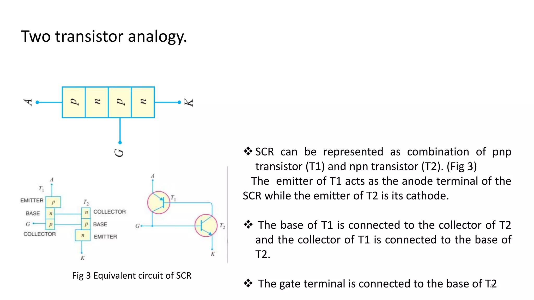
Basics of SCR
Rajesh B. Lohani
Dept. of E & TC
Goa College of Engineering
References
R. Boylestad, L. Nashelsky; Electronic Devices and Circuits, PHI.
.Mohd. Rasheed; Power Electronic Circuits, Devices and Applications; Pearson Education.
Courtesy : Google images
1
https://www.electrical4u.com/thyristor-silicon-controlled-rectifier-scr/
Learning Objectives
2
i) Explain the Construction of SCR.
ii) Understand the Operating Principle and Characteristics of SCR.
SCRSilicon Controlled Rectifier (SCR)
Unidirectional semiconductor device made of silicon.
 It is a three-terminal, four-layer device. Fig 1.
It has three junctions J1, J2 and J3.
The Fig 2 depicts the symbol of SCR with terminals
Anode(A), Cathode (K) and the Gate (G).
Fig 2 The symbol of SCR
3Fig 1 Construction of SCR
SCR (Silicon Controlled Rectifier) is a trade name
given to the thyristor by General Electric Company.
Two transistor analogy.
SCR can be represented as combination of pnp
transistor (T1) and npn transistor (T2). (Fig 3)
The emitter of T1 acts as the anode terminal of the
SCR while the emitter of T2 is its cathode.
 The base of T1 is connected to the collector of T2
and the collector of T1 is connected to the base of
T2.
 The gate terminal is connected to the base of T24
Fig 3 Equivalent circuit of SCR
Forward Blocking Mode of SCR
 A positive bias is applied to
the SCR by connecting anode
terminal (A) to the positive and
cathode terminal (K) to the
negative terminal of the battery,
making the junction J1 and J3
forward biased and junction J2
reverse biased. Fig 4. 5
Modes of operation
Fig 4 Positive bias of SCR
Fig 6 Characteristics of SCR
6
Reverse Blocking Mode of SCR
 In reverse biased condition junction
J1 and J3 reverse biased and junction J2
forward biased. , only reverse saturation
current flows through the device as
shown in the characteristic curve by blue
line. The device also exhibits the reverse
breakdown phenomenon beyond a
reverse safe voltage limit just like a diode.
Fig 5 Reverse bias of SCR Fig 6 Characteristics of SCR
Forward Conduction Mode of SCR
 The SCR can be made to conduct either
by increasing the positive voltage applied
at anode terminal (A) beyond the Break Over
Voltage, VB and or
By applying positive voltage at the gate terminal (G) as shown in the figure below.
SCR can also be turned on at a much
smaller voltage level by controlling the gate current
at the gate terminal. 7
Fig 7 Biasing of SCR
Fig 8 V-I Characteristics of SCR
8
Application of SCR as Rectifier
9
Learning Outcomes
Make use of SCR as rectifier.
Dedicated to my loving parents
Late. Janaki B. Lohani and Mr. Basant B. Lohani
(Retd. Principal)
10
11
Thank You

1 r b lohani ppt led

  • 1.
    Basics of SCR RajeshB. Lohani Dept. of E & TC Goa College of Engineering References R. Boylestad, L. Nashelsky; Electronic Devices and Circuits, PHI. .Mohd. Rasheed; Power Electronic Circuits, Devices and Applications; Pearson Education. Courtesy : Google images 1 https://www.electrical4u.com/thyristor-silicon-controlled-rectifier-scr/
  • 2.
    Learning Objectives 2 i) Explainthe Construction of SCR. ii) Understand the Operating Principle and Characteristics of SCR.
  • 3.
    SCRSilicon Controlled Rectifier(SCR) Unidirectional semiconductor device made of silicon.  It is a three-terminal, four-layer device. Fig 1. It has three junctions J1, J2 and J3. The Fig 2 depicts the symbol of SCR with terminals Anode(A), Cathode (K) and the Gate (G). Fig 2 The symbol of SCR 3Fig 1 Construction of SCR SCR (Silicon Controlled Rectifier) is a trade name given to the thyristor by General Electric Company.
  • 4.
    Two transistor analogy. SCRcan be represented as combination of pnp transistor (T1) and npn transistor (T2). (Fig 3) The emitter of T1 acts as the anode terminal of the SCR while the emitter of T2 is its cathode.  The base of T1 is connected to the collector of T2 and the collector of T1 is connected to the base of T2.  The gate terminal is connected to the base of T24 Fig 3 Equivalent circuit of SCR
  • 5.
    Forward Blocking Modeof SCR  A positive bias is applied to the SCR by connecting anode terminal (A) to the positive and cathode terminal (K) to the negative terminal of the battery, making the junction J1 and J3 forward biased and junction J2 reverse biased. Fig 4. 5 Modes of operation Fig 4 Positive bias of SCR Fig 6 Characteristics of SCR
  • 6.
    6 Reverse Blocking Modeof SCR  In reverse biased condition junction J1 and J3 reverse biased and junction J2 forward biased. , only reverse saturation current flows through the device as shown in the characteristic curve by blue line. The device also exhibits the reverse breakdown phenomenon beyond a reverse safe voltage limit just like a diode. Fig 5 Reverse bias of SCR Fig 6 Characteristics of SCR
  • 7.
    Forward Conduction Modeof SCR  The SCR can be made to conduct either by increasing the positive voltage applied at anode terminal (A) beyond the Break Over Voltage, VB and or By applying positive voltage at the gate terminal (G) as shown in the figure below. SCR can also be turned on at a much smaller voltage level by controlling the gate current at the gate terminal. 7 Fig 7 Biasing of SCR Fig 8 V-I Characteristics of SCR
  • 8.
  • 9.
    9 Learning Outcomes Make useof SCR as rectifier.
  • 10.
    Dedicated to myloving parents Late. Janaki B. Lohani and Mr. Basant B. Lohani (Retd. Principal) 10
  • 11.