1. The document discusses various thyristor devices - DIAC, TRIAC, and Quadrac. DIAC is a two-terminal bidirectional thyristor that can be triggered in either direction. TRIAC is a three-terminal bidirectional thyristor that consists of two SCRs connected in inverse parallel.
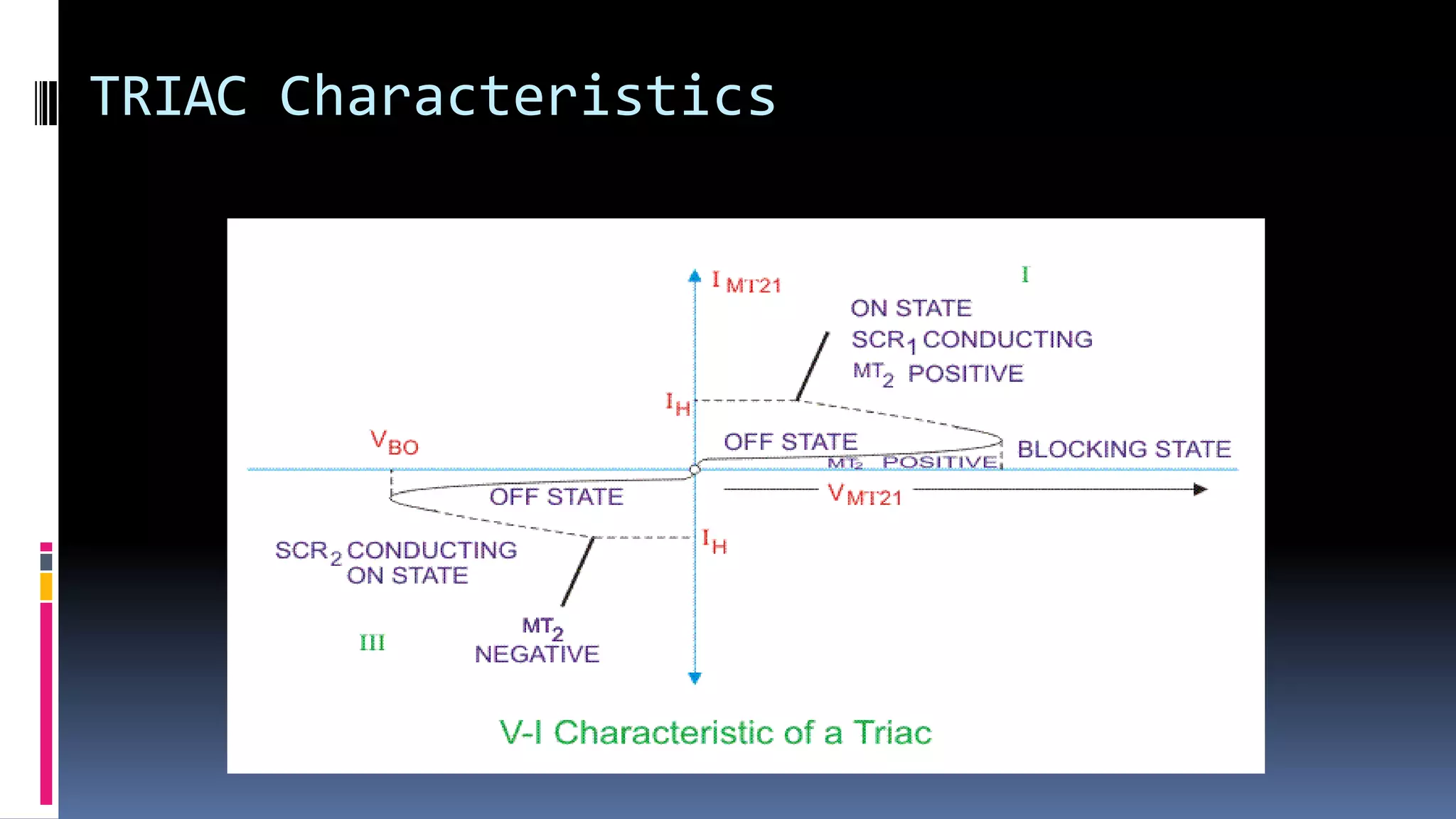
2. TRIAC can conduct current in both directions and be triggered by either positive or negative gate signals. It has four modes of operation depending on the polarity of voltages at its terminals.
3. Quadrac is a combined package that contains both a DIAC and TRIAC to provide triggering of the TRIAC. It is used in applications like light dimmers.