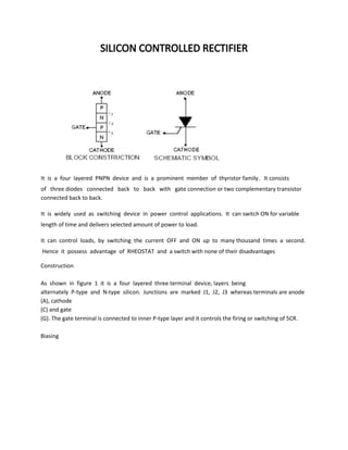
SlideShare a Scribd company logo
SILICON CONTROLLED RECTIFIER
It is a four layered PNPN device and is a prominent member of thyristor family. It consists
of three diodes connected back to back with gate connection or two complementary transistor
connected back to back.
It is widely used as switching device in power control applications. It can switch ON for variable
length of time and delivers selected amount of power to load.
It can control loads, by switching the current OFF and ON up to many thousand times a second.
Hence it possess advantage of RHEOSTAT and a switch with none of their disadvantages
Construction
As shown in figure 1 it is a four layered three terminal device, layers being
alternately P-type and N-type silicon. Junctions are marked J1, J2, J3 whereas terminals are anode
(A), cathode
(C) and gate
(G). The gate terminal is connected to inner P-type layer and it controls the firing or switching of 5CR.
Biasing
The biasing of SCR is shown in figure
1(a). The junction J1 and J3 become
forward biased while J2 is reverse biased. In figure 1 polarity is reversed. It is seen that now junction J1
and J3 become reverse biased and only J2 is forward biased.
Operation of SCR
In SCR a load is connected in series with anode and is kept at positive potential with respect to
cathode when the gate is open i.e., no voltage is applied at the gate.
Under this condition, junctions J1 and J3 are for ward biased and junction J2 is reverse biased. Due to
this, no current flows through RL and hence the 8CR is cutoff.
However when the anode voltage is increased gradually to breakover
voltage, then breakdown occurs at junction J due to this charge carriers are able to flow from
cathode to anode easily, hence SCR starts conducting and is said tobe in ON state.
The SCR offers very small forward resistance so that it allows infinitely
high current. The current flowing through the 8CR is limited only by the anode voltage and
external resistance.
If the battery connections of the applied voltage are reversed as shown in figure 2 the junction J1
and J3 are reverse biased. J2 is forward biased.
If the applied reverse voltage is small the SCR is OFF and hence no current flows through the
device.
If the reverse voltage is increased to reverse breakdown voltage, the junction J1 and J3 will breakdown
due to avalanche effect. This causes current to flow through the SCR.
From the above discussion we conclude that the SCR can be used to conduct only in forward direction.
Therefore SCR is called as “unidirectional device”.
Vl Characteristics of SCR
The “forward characteristics” of SCR may be obtained using the figure 3.
The volt-ampere characteristics of a SCR for IG = 0 is shown in figure 3.
As the applied anode to cathode voltage is increased above zero, very small current flows through the
device, under this condition the 5CR is off. It will be
continued until; the applied voltage reaches the forward Breakover voltage (point A).
if the anode-cathode (applied) voltage exceeds the Breakover voltage it conducts heavily the SCR
turns ON and anode to cathode voltage decreases
quickly to a point B because, under this condition the 5CR offers very low resistance hence it
drops very low voltage across it.
At this stage the 5CR allows more current to low through it. The amplitude
of the current is depending upon the supply voltage and load resistance connected in the
circuit.
The current corresponding to the point ‘B’ is called the “holding current (IH)” It can be defined as the
minimum value of anode current required to keep
the SCR in ON State. If the 5CR falls below this holding current the SCR turns OFF.
If the value of the gate current I is increased above zero, (‘G > O) the SCR turns ON even at lower
Breakover voltage as shown in figure 3(b).
The region lying between the points OA is called forward blocking region.
In this region 5CR is OFF’. The region lying between the points BC is called forward conduction
region. In this region SCR is ON.
Once the SCR is switched ON then the gate looses all the control. So SOB cannot be turned OFF
by varying the gate voltage. It is possible only by reducing the applied voltage.
To obtain the “reverse characteristics”the following points are followed.
1.In this case the SCR is reverse biased, if the applied reverse voltage is
increased above zero, hence a very small current flows through the SCR.
Under this condition the SCR is OFF, it continues till the applied reverse voltage reaches
breakdown voltage.
2.As the applied reverse voltage is increased above the breakdown voltage, the
avalanche breakdown occurs hence 5CR starts conducting in the reverse direction. It is shown in
curve DE. Suppose the applied voltage is increased to a very high value, the device may get damaged.
SCR rating
The SCR rating are defined as follows
1) “Forward Breakover voltage”:It is the voltage at which the 5CR is
switched from its OFF position to ON position. Its: values are maximum for zero gate current, its
values lie in the range of 50 to l200volts
2) “Holding current”: it is the minimum value of anode current required to keep the SCR in ON
position.
3) “Gate triggering current”: It is the value of anode current necessary to switch 5CR from OFF
to ON position under specified condition. It is typically about 4OmA.
4) “Average forward current”: It is the maximum value of anode current at which the 5CR can handle
in its ON position. Its value lies in the range of 1 to 1800Amps.
5) “Reverse breakdown voltage”: It is the value of reverse voltage between cathode to anode at which
the avalanche breakdown occurs.
6) “Turn ON time – TON”: It can be defined as, the time required to switch it from OFF to ON state when
triggering signal is applied. TON decreases if the trigger voltage is increased; TON is increases when
anode current increases.
7) “Turn OFF Time – TOFF”: It is the time required to switch it from ON to
OFF state by dropping anode voltage. TOFF is small if anode voltage in reverse direction and
increases with temperature and anode current.
8) “Gate Recovery time”: It is the time required for which anode voltage is reduced to VH to
turn OFF SCR.
Basic Operation of an SCR
The operation of a PNPN device can best be visualized as a specially coupled
pair of transistors as shown in Figure
The connections between the two transistors are such that regenerative action can occur when a
proper gate signal is applied to the base of the NPN transistor. Normal
leakage current is so low that the combined hFE of the specially coupled two-
transistor feedback amplifier is less than unity, thus keeping the circuit in an off-
state condition. A momentary positive pulse applied to the gate will bias the NPN transistor into
conduction which, in turn, biases the PNP transistor into
conduction. The effective hFE momentarily becomes greater than unity so that the specially
coupled transistors saturate. Once saturated, current through the transistors is enough to keep the
combined hFE greater than unity. The circuit will remain “on”
until it is “turned off” by reducing the anode-to-cathode current (IT) such that the
combined hFE is less than unity and regeneration ceases; this threshold anode current is the
holding current of the SCR.
Electrical Characteristic Curves of Thyristors V-I Characteristics of SCR Device
Methods of Switching on Thyristors There are three general ways to switch thyristors to on-state
condition:
Application of Gate Signal
Static dv/dt Turn-On
Voltage Breakover Turn-On
Listed below is a brief description of each method.
Application Of Gate Signal
For an SCR (unilateral device), this signal must be positive with respect to the cathode polarity. A triac
(bilateral device) can be turned on with gate signal of either
polarity; however, different polarities have different requirements of IGT and VGT which must be
satisfied. Since a diac does not have a gate, this method of turn-on is not applicable to diacs; in fact,
the single major application of diacs is to switch-on triacs.
Static dv/dt Turn-On
Comes from a fast rising voltage applied across the anode and cathode terminals of an SCR or the
main terminals of a triac. Due to the nature of thyristor
construction, a small junction capacitor is formed across each PN junction. Figure
14.14 shows how typical internal capacitors are linked in gated thyristors. When
voltage is impressed suddenly across a PN junction, a charging current will flow which is equal to:
i = C (dv/dt)
When c (dv/dt) becomes greater or equal to thyristor IGT, the
thyristor switches on. Normally, this type of turn on does not damage or hurt the device
providing the surge current is limited. Generally, thyristor application circuits are designed with static
dv/dt snubber networks if fast rising voltages are
anticipated.
Voltage Breakover Turn-On
Is the method used to switch on diacs. However, exceeding voltage break over of SCRs and triacs is
definitely not recommended as a turn-on method. In the case
of SCRs and triacs, the leakage current increases until it exceeds the gate current
required to turn-on these gated thyristors in a small localized point. When turn-on occurs by this
method, there is localized heating in a small area which may melt
the silicon or damage the device if di/dt of the increasing current is not sufficiently
limited. Diacs used in typical phase control circuits are basically protected against
excessive current at breakover as long as the firing capacitor is not excessively large. When diacs
are used in a zener function, current limiting is necessary.
Source : http://mediatoget.blogspot.in/2011/10/silicon-controlled-
rectifier.html

More Related Content

What's hot

Single phase full bridge inverter
Single phase full bridge inverterSingle phase full bridge inverter
Single phase full bridge inverter
Nisarg Amin
 
Silicon controlled rectifier ( SCR )
Silicon controlled rectifier ( SCR )Silicon controlled rectifier ( SCR )
Silicon controlled rectifier ( SCR )
DikshaTripathi20
 
Gunn Diode
Gunn Diode Gunn Diode
Gunn Diode
Homework Guru
 
Diac and triac basics
Diac and triac   basicsDiac and triac   basics
Diac and triac basics
AtheenaPandian Enterprises
 
SCR
SCRSCR
TRIAC
TRIACTRIAC
(D/A) and (A/D)conversion
(D/A) and (A/D)conversion(D/A) and (A/D)conversion
(D/A) and (A/D)conversion
Praveen Kumar
 
Field Effect Transistor
Field Effect TransistorField Effect Transistor
Field Effect Transistor
Jess Rangcasajo
 
Chopper operation
Chopper  operationChopper  operation
Chopper operation
vishalgohel12195
 
IGBT
IGBTIGBT
SCR
SCRSCR
Switch mode power supply
Switch mode power supplySwitch mode power supply
Switch mode power supplyAnish Das
 
Choppers
ChoppersChoppers
Diode voltage multiplier
Diode voltage multiplierDiode voltage multiplier
Diode voltage multiplier
Unsa Shakir
 
Power Electronics - DIAC & TRIAC
Power Electronics - DIAC & TRIACPower Electronics - DIAC & TRIAC
Power Electronics - DIAC & TRIAC
Burdwan University
 
DC DC Converter
DC DC ConverterDC DC Converter
DC DC Converter
Mengstu Fentaw
 
Silicon controlled rectifier
Silicon controlled rectifierSilicon controlled rectifier
Silicon controlled rectifier
Ranjith Samala
 
Digital storage ocilloscope
Digital storage ocilloscopeDigital storage ocilloscope
Digital storage ocilloscope
kajal8899
 
Handoff in Mobile Communication
Handoff in Mobile CommunicationHandoff in Mobile Communication
Handoff in Mobile Communication
Noushad Hasan
 
Current Source Inverter
Current Source InverterCurrent Source Inverter
Current Source Inverter
Rajendra Gharase
 

What's hot (20)

Single phase full bridge inverter
Single phase full bridge inverterSingle phase full bridge inverter
Single phase full bridge inverter
 
Silicon controlled rectifier ( SCR )
Silicon controlled rectifier ( SCR )Silicon controlled rectifier ( SCR )
Silicon controlled rectifier ( SCR )
 
Gunn Diode
Gunn Diode Gunn Diode
Gunn Diode
 
Diac and triac basics
Diac and triac   basicsDiac and triac   basics
Diac and triac basics
 
SCR
SCRSCR
SCR
 
TRIAC
TRIACTRIAC
TRIAC
 
(D/A) and (A/D)conversion
(D/A) and (A/D)conversion(D/A) and (A/D)conversion
(D/A) and (A/D)conversion
 
Field Effect Transistor
Field Effect TransistorField Effect Transistor
Field Effect Transistor
 
Chopper operation
Chopper  operationChopper  operation
Chopper operation
 
IGBT
IGBTIGBT
IGBT
 
SCR
SCRSCR
SCR
 
Switch mode power supply
Switch mode power supplySwitch mode power supply
Switch mode power supply
 
Choppers
ChoppersChoppers
Choppers
 
Diode voltage multiplier
Diode voltage multiplierDiode voltage multiplier
Diode voltage multiplier
 
Power Electronics - DIAC & TRIAC
Power Electronics - DIAC & TRIACPower Electronics - DIAC & TRIAC
Power Electronics - DIAC & TRIAC
 
DC DC Converter
DC DC ConverterDC DC Converter
DC DC Converter
 
Silicon controlled rectifier
Silicon controlled rectifierSilicon controlled rectifier
Silicon controlled rectifier
 
Digital storage ocilloscope
Digital storage ocilloscopeDigital storage ocilloscope
Digital storage ocilloscope
 
Handoff in Mobile Communication
Handoff in Mobile CommunicationHandoff in Mobile Communication
Handoff in Mobile Communication
 
Current Source Inverter
Current Source InverterCurrent Source Inverter
Current Source Inverter
 

Similar to Silicon controlled rectifier

R b lohani thyristor
R b lohani thyristorR b lohani thyristor
R b lohani thyristor
ssuser4b487e1
 
Scr
ScrScr
Power Electronics Lab (part-1).docx
Power Electronics Lab (part-1).docxPower Electronics Lab (part-1).docx
Power Electronics Lab (part-1).docx
Muhammadzohaib653589
 
Thyrister/SCR
Thyrister/SCRThyrister/SCR
Thyrister/SCR
Ashvani Shukla
 
Thyristor Characteristics, Two Transistor Model Of Thyristor & Thyrisror Turn...
Thyristor Characteristics, Two Transistor Model Of Thyristor & Thyrisror Turn...Thyristor Characteristics, Two Transistor Model Of Thyristor & Thyrisror Turn...
Thyristor Characteristics, Two Transistor Model Of Thyristor & Thyrisror Turn...
University of Gujrat, Pakistan
 
Module 2 thyristors
Module 2 thyristorsModule 2 thyristors
Module 2 thyristors
ZahiraTabassum1
 
Introduction to scr thyristers
Introduction to scr thyristersIntroduction to scr thyristers
Introduction to scr thyristers
iqtadar ali gilani
 
Module 2 thyristors
Module 2 thyristorsModule 2 thyristors
Module 2 thyristors
Amreen Khanam
 
Thyristors (2)
Thyristors (2)Thyristors (2)
Thyristors (2)Chethan Sp
 
powerelectronics-switch.pptx for Engineering students
powerelectronics-switch.pptx for Engineering studentspowerelectronics-switch.pptx for Engineering students
powerelectronics-switch.pptx for Engineering students
Muhammadusman112116
 
Power Electronics Basics_Sonam Welanjkar
Power Electronics Basics_Sonam WelanjkarPower Electronics Basics_Sonam Welanjkar
Power Electronics Basics_Sonam Welanjkar
Sonam Welanjkar
 
Power Electronic Devices
Power Electronic DevicesPower Electronic Devices
Power Electronic Devices
maneesh001
 
SCR NEW FOR TOMMOROW.pdf
SCR  NEW FOR TOMMOROW.pdfSCR  NEW FOR TOMMOROW.pdf
SCR NEW FOR TOMMOROW.pdf
yogeshkute
 
POWER ELECTRONICS CHAPTER - 1.pdf
POWER ELECTRONICS     CHAPTER - 1.pdfPOWER ELECTRONICS     CHAPTER - 1.pdf
POWER ELECTRONICS CHAPTER - 1.pdf
mjayaprasanth2608200
 
Pex ppt.pdf
Pex ppt.pdfPex ppt.pdf
Pex ppt.pdf
ChaityaGala1
 
Applications of power electronic device to power system
Applications of power electronic device to power systemApplications of power electronic device to power system
Applications of power electronic device to power system
swathiammu7
 
SCR.pptx
SCR.pptxSCR.pptx
SCR.pptx
raviarmugam
 
lecture1424354515.pdf
lecture1424354515.pdflecture1424354515.pdf
lecture1424354515.pdf
LucasMogaka
 

Similar to Silicon controlled rectifier (20)

R b lohani thyristor
R b lohani thyristorR b lohani thyristor
R b lohani thyristor
 
Scr
ScrScr
Scr
 
Power Electronics Lab (part-1).docx
Power Electronics Lab (part-1).docxPower Electronics Lab (part-1).docx
Power Electronics Lab (part-1).docx
 
Thyrister/SCR
Thyrister/SCRThyrister/SCR
Thyrister/SCR
 
Thyristor Characteristics, Two Transistor Model Of Thyristor & Thyrisror Turn...
Thyristor Characteristics, Two Transistor Model Of Thyristor & Thyrisror Turn...Thyristor Characteristics, Two Transistor Model Of Thyristor & Thyrisror Turn...
Thyristor Characteristics, Two Transistor Model Of Thyristor & Thyrisror Turn...
 
Module 2 thyristors
Module 2 thyristorsModule 2 thyristors
Module 2 thyristors
 
Introduction to scr thyristers
Introduction to scr thyristersIntroduction to scr thyristers
Introduction to scr thyristers
 
Module 2 thyristors
Module 2 thyristorsModule 2 thyristors
Module 2 thyristors
 
Thyristors (2)
Thyristors (2)Thyristors (2)
Thyristors (2)
 
SCR
SCRSCR
SCR
 
powerelectronics-switch.pptx for Engineering students
powerelectronics-switch.pptx for Engineering studentspowerelectronics-switch.pptx for Engineering students
powerelectronics-switch.pptx for Engineering students
 
Power Electronics Basics_Sonam Welanjkar
Power Electronics Basics_Sonam WelanjkarPower Electronics Basics_Sonam Welanjkar
Power Electronics Basics_Sonam Welanjkar
 
Power Electronic Devices
Power Electronic DevicesPower Electronic Devices
Power Electronic Devices
 
SCR NEW FOR TOMMOROW.pdf
SCR  NEW FOR TOMMOROW.pdfSCR  NEW FOR TOMMOROW.pdf
SCR NEW FOR TOMMOROW.pdf
 
POWER ELECTRONICS CHAPTER - 1.pdf
POWER ELECTRONICS     CHAPTER - 1.pdfPOWER ELECTRONICS     CHAPTER - 1.pdf
POWER ELECTRONICS CHAPTER - 1.pdf
 
Pex ppt.pdf
Pex ppt.pdfPex ppt.pdf
Pex ppt.pdf
 
Applications of power electronic device to power system
Applications of power electronic device to power systemApplications of power electronic device to power system
Applications of power electronic device to power system
 
Lab sheet
Lab sheetLab sheet
Lab sheet
 
SCR.pptx
SCR.pptxSCR.pptx
SCR.pptx
 
lecture1424354515.pdf
lecture1424354515.pdflecture1424354515.pdf
lecture1424354515.pdf
 

Recently uploaded

DESIGN A COTTON SEED SEPARATION MACHINE.docx
DESIGN A COTTON SEED SEPARATION MACHINE.docxDESIGN A COTTON SEED SEPARATION MACHINE.docx
DESIGN A COTTON SEED SEPARATION MACHINE.docx
FluxPrime1
 
Planning Of Procurement o different goods and services
Planning Of Procurement o different goods and servicesPlanning Of Procurement o different goods and services
Planning Of Procurement o different goods and services
JoytuBarua2
 
CFD Simulation of By-pass Flow in a HRSG module by R&R Consult.pptx
CFD Simulation of By-pass Flow in a HRSG module by R&R Consult.pptxCFD Simulation of By-pass Flow in a HRSG module by R&R Consult.pptx
CFD Simulation of By-pass Flow in a HRSG module by R&R Consult.pptx
R&R Consult
 
NO1 Uk best vashikaran specialist in delhi vashikaran baba near me online vas...
NO1 Uk best vashikaran specialist in delhi vashikaran baba near me online vas...NO1 Uk best vashikaran specialist in delhi vashikaran baba near me online vas...
NO1 Uk best vashikaran specialist in delhi vashikaran baba near me online vas...
Amil Baba Dawood bangali
 
Design and Analysis of Algorithms-DP,Backtracking,Graphs,B&B
Design and Analysis of Algorithms-DP,Backtracking,Graphs,B&BDesign and Analysis of Algorithms-DP,Backtracking,Graphs,B&B
Design and Analysis of Algorithms-DP,Backtracking,Graphs,B&B
Sreedhar Chowdam
 
Gen AI Study Jams _ For the GDSC Leads in India.pdf
Gen AI Study Jams _ For the GDSC Leads in India.pdfGen AI Study Jams _ For the GDSC Leads in India.pdf
Gen AI Study Jams _ For the GDSC Leads in India.pdf
gdsczhcet
 
Sachpazis:Terzaghi Bearing Capacity Estimation in simple terms with Calculati...
Sachpazis:Terzaghi Bearing Capacity Estimation in simple terms with Calculati...Sachpazis:Terzaghi Bearing Capacity Estimation in simple terms with Calculati...
Sachpazis:Terzaghi Bearing Capacity Estimation in simple terms with Calculati...
Dr.Costas Sachpazis
 
ML for identifying fraud using open blockchain data.pptx
ML for identifying fraud using open blockchain data.pptxML for identifying fraud using open blockchain data.pptx
ML for identifying fraud using open blockchain data.pptx
Vijay Dialani, PhD
 
Nuclear Power Economics and Structuring 2024
Nuclear Power Economics and Structuring 2024Nuclear Power Economics and Structuring 2024
Nuclear Power Economics and Structuring 2024
Massimo Talia
 
在线办理(ANU毕业证书)澳洲国立大学毕业证录取通知书一模一样
在线办理(ANU毕业证书)澳洲国立大学毕业证录取通知书一模一样在线办理(ANU毕业证书)澳洲国立大学毕业证录取通知书一模一样
在线办理(ANU毕业证书)澳洲国立大学毕业证录取通知书一模一样
obonagu
 
Final project report on grocery store management system..pdf
Final project report on grocery store management system..pdfFinal project report on grocery store management system..pdf
Final project report on grocery store management system..pdf
Kamal Acharya
 
Top 10 Oil and Gas Projects in Saudi Arabia 2024.pdf
Top 10 Oil and Gas Projects in Saudi Arabia 2024.pdfTop 10 Oil and Gas Projects in Saudi Arabia 2024.pdf
Top 10 Oil and Gas Projects in Saudi Arabia 2024.pdf
Teleport Manpower Consultant
 
power quality voltage fluctuation UNIT - I.pptx
power quality voltage fluctuation UNIT - I.pptxpower quality voltage fluctuation UNIT - I.pptx
power quality voltage fluctuation UNIT - I.pptx
ViniHema
 
H.Seo, ICLR 2024, MLILAB, KAIST AI.pdf
H.Seo,  ICLR 2024, MLILAB,  KAIST AI.pdfH.Seo,  ICLR 2024, MLILAB,  KAIST AI.pdf
H.Seo, ICLR 2024, MLILAB, KAIST AI.pdf
MLILAB
 
ethical hacking-mobile hacking methods.ppt
ethical hacking-mobile hacking methods.pptethical hacking-mobile hacking methods.ppt
ethical hacking-mobile hacking methods.ppt
Jayaprasanna4
 
一比一原版(SFU毕业证)西蒙菲莎大学毕业证成绩单如何办理
一比一原版(SFU毕业证)西蒙菲莎大学毕业证成绩单如何办理一比一原版(SFU毕业证)西蒙菲莎大学毕业证成绩单如何办理
一比一原版(SFU毕业证)西蒙菲莎大学毕业证成绩单如何办理
bakpo1
 
road safety engineering r s e unit 3.pdf
road safety engineering  r s e unit 3.pdfroad safety engineering  r s e unit 3.pdf
road safety engineering r s e unit 3.pdf
VENKATESHvenky89705
 
Cosmetic shop management system project report.pdf
Cosmetic shop management system project report.pdfCosmetic shop management system project report.pdf
Cosmetic shop management system project report.pdf
Kamal Acharya
 
ethical hacking in wireless-hacking1.ppt
ethical hacking in wireless-hacking1.pptethical hacking in wireless-hacking1.ppt
ethical hacking in wireless-hacking1.ppt
Jayaprasanna4
 
Pile Foundation by Venkatesh Taduvai (Sub Geotechnical Engineering II)-conver...
Pile Foundation by Venkatesh Taduvai (Sub Geotechnical Engineering II)-conver...Pile Foundation by Venkatesh Taduvai (Sub Geotechnical Engineering II)-conver...
Pile Foundation by Venkatesh Taduvai (Sub Geotechnical Engineering II)-conver...
AJAYKUMARPUND1
 

Recently uploaded (20)

DESIGN A COTTON SEED SEPARATION MACHINE.docx
DESIGN A COTTON SEED SEPARATION MACHINE.docxDESIGN A COTTON SEED SEPARATION MACHINE.docx
DESIGN A COTTON SEED SEPARATION MACHINE.docx
 
Planning Of Procurement o different goods and services
Planning Of Procurement o different goods and servicesPlanning Of Procurement o different goods and services
Planning Of Procurement o different goods and services
 
CFD Simulation of By-pass Flow in a HRSG module by R&R Consult.pptx
CFD Simulation of By-pass Flow in a HRSG module by R&R Consult.pptxCFD Simulation of By-pass Flow in a HRSG module by R&R Consult.pptx
CFD Simulation of By-pass Flow in a HRSG module by R&R Consult.pptx
 
NO1 Uk best vashikaran specialist in delhi vashikaran baba near me online vas...
NO1 Uk best vashikaran specialist in delhi vashikaran baba near me online vas...NO1 Uk best vashikaran specialist in delhi vashikaran baba near me online vas...
NO1 Uk best vashikaran specialist in delhi vashikaran baba near me online vas...
 
Design and Analysis of Algorithms-DP,Backtracking,Graphs,B&B
Design and Analysis of Algorithms-DP,Backtracking,Graphs,B&BDesign and Analysis of Algorithms-DP,Backtracking,Graphs,B&B
Design and Analysis of Algorithms-DP,Backtracking,Graphs,B&B
 
Gen AI Study Jams _ For the GDSC Leads in India.pdf
Gen AI Study Jams _ For the GDSC Leads in India.pdfGen AI Study Jams _ For the GDSC Leads in India.pdf
Gen AI Study Jams _ For the GDSC Leads in India.pdf
 
Sachpazis:Terzaghi Bearing Capacity Estimation in simple terms with Calculati...
Sachpazis:Terzaghi Bearing Capacity Estimation in simple terms with Calculati...Sachpazis:Terzaghi Bearing Capacity Estimation in simple terms with Calculati...
Sachpazis:Terzaghi Bearing Capacity Estimation in simple terms with Calculati...
 
ML for identifying fraud using open blockchain data.pptx
ML for identifying fraud using open blockchain data.pptxML for identifying fraud using open blockchain data.pptx
ML for identifying fraud using open blockchain data.pptx
 
Nuclear Power Economics and Structuring 2024
Nuclear Power Economics and Structuring 2024Nuclear Power Economics and Structuring 2024
Nuclear Power Economics and Structuring 2024
 
在线办理(ANU毕业证书)澳洲国立大学毕业证录取通知书一模一样
在线办理(ANU毕业证书)澳洲国立大学毕业证录取通知书一模一样在线办理(ANU毕业证书)澳洲国立大学毕业证录取通知书一模一样
在线办理(ANU毕业证书)澳洲国立大学毕业证录取通知书一模一样
 
Final project report on grocery store management system..pdf
Final project report on grocery store management system..pdfFinal project report on grocery store management system..pdf
Final project report on grocery store management system..pdf
 
Top 10 Oil and Gas Projects in Saudi Arabia 2024.pdf
Top 10 Oil and Gas Projects in Saudi Arabia 2024.pdfTop 10 Oil and Gas Projects in Saudi Arabia 2024.pdf
Top 10 Oil and Gas Projects in Saudi Arabia 2024.pdf
 
power quality voltage fluctuation UNIT - I.pptx
power quality voltage fluctuation UNIT - I.pptxpower quality voltage fluctuation UNIT - I.pptx
power quality voltage fluctuation UNIT - I.pptx
 
H.Seo, ICLR 2024, MLILAB, KAIST AI.pdf
H.Seo,  ICLR 2024, MLILAB,  KAIST AI.pdfH.Seo,  ICLR 2024, MLILAB,  KAIST AI.pdf
H.Seo, ICLR 2024, MLILAB, KAIST AI.pdf
 
ethical hacking-mobile hacking methods.ppt
ethical hacking-mobile hacking methods.pptethical hacking-mobile hacking methods.ppt
ethical hacking-mobile hacking methods.ppt
 
一比一原版(SFU毕业证)西蒙菲莎大学毕业证成绩单如何办理
一比一原版(SFU毕业证)西蒙菲莎大学毕业证成绩单如何办理一比一原版(SFU毕业证)西蒙菲莎大学毕业证成绩单如何办理
一比一原版(SFU毕业证)西蒙菲莎大学毕业证成绩单如何办理
 
road safety engineering r s e unit 3.pdf
road safety engineering  r s e unit 3.pdfroad safety engineering  r s e unit 3.pdf
road safety engineering r s e unit 3.pdf
 
Cosmetic shop management system project report.pdf
Cosmetic shop management system project report.pdfCosmetic shop management system project report.pdf
Cosmetic shop management system project report.pdf
 
ethical hacking in wireless-hacking1.ppt
ethical hacking in wireless-hacking1.pptethical hacking in wireless-hacking1.ppt
ethical hacking in wireless-hacking1.ppt
 
Pile Foundation by Venkatesh Taduvai (Sub Geotechnical Engineering II)-conver...
Pile Foundation by Venkatesh Taduvai (Sub Geotechnical Engineering II)-conver...Pile Foundation by Venkatesh Taduvai (Sub Geotechnical Engineering II)-conver...
Pile Foundation by Venkatesh Taduvai (Sub Geotechnical Engineering II)-conver...
 

Silicon controlled rectifier

  • 1. SILICON CONTROLLED RECTIFIER It is a four layered PNPN device and is a prominent member of thyristor family. It consists of three diodes connected back to back with gate connection or two complementary transistor connected back to back. It is widely used as switching device in power control applications. It can switch ON for variable length of time and delivers selected amount of power to load. It can control loads, by switching the current OFF and ON up to many thousand times a second. Hence it possess advantage of RHEOSTAT and a switch with none of their disadvantages Construction As shown in figure 1 it is a four layered three terminal device, layers being alternately P-type and N-type silicon. Junctions are marked J1, J2, J3 whereas terminals are anode (A), cathode (C) and gate (G). The gate terminal is connected to inner P-type layer and it controls the firing or switching of 5CR. Biasing
  • 2. The biasing of SCR is shown in figure 1(a). The junction J1 and J3 become forward biased while J2 is reverse biased. In figure 1 polarity is reversed. It is seen that now junction J1 and J3 become reverse biased and only J2 is forward biased. Operation of SCR In SCR a load is connected in series with anode and is kept at positive potential with respect to cathode when the gate is open i.e., no voltage is applied at the gate. Under this condition, junctions J1 and J3 are for ward biased and junction J2 is reverse biased. Due to this, no current flows through RL and hence the 8CR is cutoff. However when the anode voltage is increased gradually to breakover voltage, then breakdown occurs at junction J due to this charge carriers are able to flow from cathode to anode easily, hence SCR starts conducting and is said tobe in ON state. The SCR offers very small forward resistance so that it allows infinitely high current. The current flowing through the 8CR is limited only by the anode voltage and external resistance.
  • 3. If the battery connections of the applied voltage are reversed as shown in figure 2 the junction J1 and J3 are reverse biased. J2 is forward biased. If the applied reverse voltage is small the SCR is OFF and hence no current flows through the device. If the reverse voltage is increased to reverse breakdown voltage, the junction J1 and J3 will breakdown due to avalanche effect. This causes current to flow through the SCR. From the above discussion we conclude that the SCR can be used to conduct only in forward direction. Therefore SCR is called as “unidirectional device”. Vl Characteristics of SCR The “forward characteristics” of SCR may be obtained using the figure 3. The volt-ampere characteristics of a SCR for IG = 0 is shown in figure 3.
  • 4. As the applied anode to cathode voltage is increased above zero, very small current flows through the device, under this condition the 5CR is off. It will be continued until; the applied voltage reaches the forward Breakover voltage (point A). if the anode-cathode (applied) voltage exceeds the Breakover voltage it conducts heavily the SCR turns ON and anode to cathode voltage decreases quickly to a point B because, under this condition the 5CR offers very low resistance hence it drops very low voltage across it. At this stage the 5CR allows more current to low through it. The amplitude of the current is depending upon the supply voltage and load resistance connected in the circuit. The current corresponding to the point ‘B’ is called the “holding current (IH)” It can be defined as the minimum value of anode current required to keep the SCR in ON State. If the 5CR falls below this holding current the SCR turns OFF. If the value of the gate current I is increased above zero, (‘G > O) the SCR turns ON even at lower Breakover voltage as shown in figure 3(b). The region lying between the points OA is called forward blocking region. In this region 5CR is OFF’. The region lying between the points BC is called forward conduction region. In this region SCR is ON.
  • 5. Once the SCR is switched ON then the gate looses all the control. So SOB cannot be turned OFF by varying the gate voltage. It is possible only by reducing the applied voltage. To obtain the “reverse characteristics”the following points are followed. 1.In this case the SCR is reverse biased, if the applied reverse voltage is increased above zero, hence a very small current flows through the SCR. Under this condition the SCR is OFF, it continues till the applied reverse voltage reaches breakdown voltage. 2.As the applied reverse voltage is increased above the breakdown voltage, the avalanche breakdown occurs hence 5CR starts conducting in the reverse direction. It is shown in curve DE. Suppose the applied voltage is increased to a very high value, the device may get damaged. SCR rating The SCR rating are defined as follows 1) “Forward Breakover voltage”:It is the voltage at which the 5CR is switched from its OFF position to ON position. Its: values are maximum for zero gate current, its values lie in the range of 50 to l200volts 2) “Holding current”: it is the minimum value of anode current required to keep the SCR in ON position. 3) “Gate triggering current”: It is the value of anode current necessary to switch 5CR from OFF to ON position under specified condition. It is typically about 4OmA. 4) “Average forward current”: It is the maximum value of anode current at which the 5CR can handle in its ON position. Its value lies in the range of 1 to 1800Amps. 5) “Reverse breakdown voltage”: It is the value of reverse voltage between cathode to anode at which the avalanche breakdown occurs. 6) “Turn ON time – TON”: It can be defined as, the time required to switch it from OFF to ON state when triggering signal is applied. TON decreases if the trigger voltage is increased; TON is increases when anode current increases. 7) “Turn OFF Time – TOFF”: It is the time required to switch it from ON to OFF state by dropping anode voltage. TOFF is small if anode voltage in reverse direction and increases with temperature and anode current.
  • 6. 8) “Gate Recovery time”: It is the time required for which anode voltage is reduced to VH to turn OFF SCR. Basic Operation of an SCR The operation of a PNPN device can best be visualized as a specially coupled pair of transistors as shown in Figure
  • 7. The connections between the two transistors are such that regenerative action can occur when a proper gate signal is applied to the base of the NPN transistor. Normal leakage current is so low that the combined hFE of the specially coupled two- transistor feedback amplifier is less than unity, thus keeping the circuit in an off- state condition. A momentary positive pulse applied to the gate will bias the NPN transistor into conduction which, in turn, biases the PNP transistor into conduction. The effective hFE momentarily becomes greater than unity so that the specially coupled transistors saturate. Once saturated, current through the transistors is enough to keep the combined hFE greater than unity. The circuit will remain “on” until it is “turned off” by reducing the anode-to-cathode current (IT) such that the combined hFE is less than unity and regeneration ceases; this threshold anode current is the holding current of the SCR. Electrical Characteristic Curves of Thyristors V-I Characteristics of SCR Device
  • 8. Methods of Switching on Thyristors There are three general ways to switch thyristors to on-state condition: Application of Gate Signal Static dv/dt Turn-On Voltage Breakover Turn-On Listed below is a brief description of each method. Application Of Gate Signal For an SCR (unilateral device), this signal must be positive with respect to the cathode polarity. A triac (bilateral device) can be turned on with gate signal of either polarity; however, different polarities have different requirements of IGT and VGT which must be satisfied. Since a diac does not have a gate, this method of turn-on is not applicable to diacs; in fact, the single major application of diacs is to switch-on triacs. Static dv/dt Turn-On Comes from a fast rising voltage applied across the anode and cathode terminals of an SCR or the main terminals of a triac. Due to the nature of thyristor construction, a small junction capacitor is formed across each PN junction. Figure 14.14 shows how typical internal capacitors are linked in gated thyristors. When voltage is impressed suddenly across a PN junction, a charging current will flow which is equal to: i = C (dv/dt) When c (dv/dt) becomes greater or equal to thyristor IGT, the thyristor switches on. Normally, this type of turn on does not damage or hurt the device providing the surge current is limited. Generally, thyristor application circuits are designed with static dv/dt snubber networks if fast rising voltages are anticipated. Voltage Breakover Turn-On Is the method used to switch on diacs. However, exceeding voltage break over of SCRs and triacs is definitely not recommended as a turn-on method. In the case of SCRs and triacs, the leakage current increases until it exceeds the gate current required to turn-on these gated thyristors in a small localized point. When turn-on occurs by this method, there is localized heating in a small area which may melt
  • 9. the silicon or damage the device if di/dt of the increasing current is not sufficiently limited. Diacs used in typical phase control circuits are basically protected against excessive current at breakover as long as the firing capacitor is not excessively large. When diacs are used in a zener function, current limiting is necessary. Source : http://mediatoget.blogspot.in/2011/10/silicon-controlled- rectifier.html