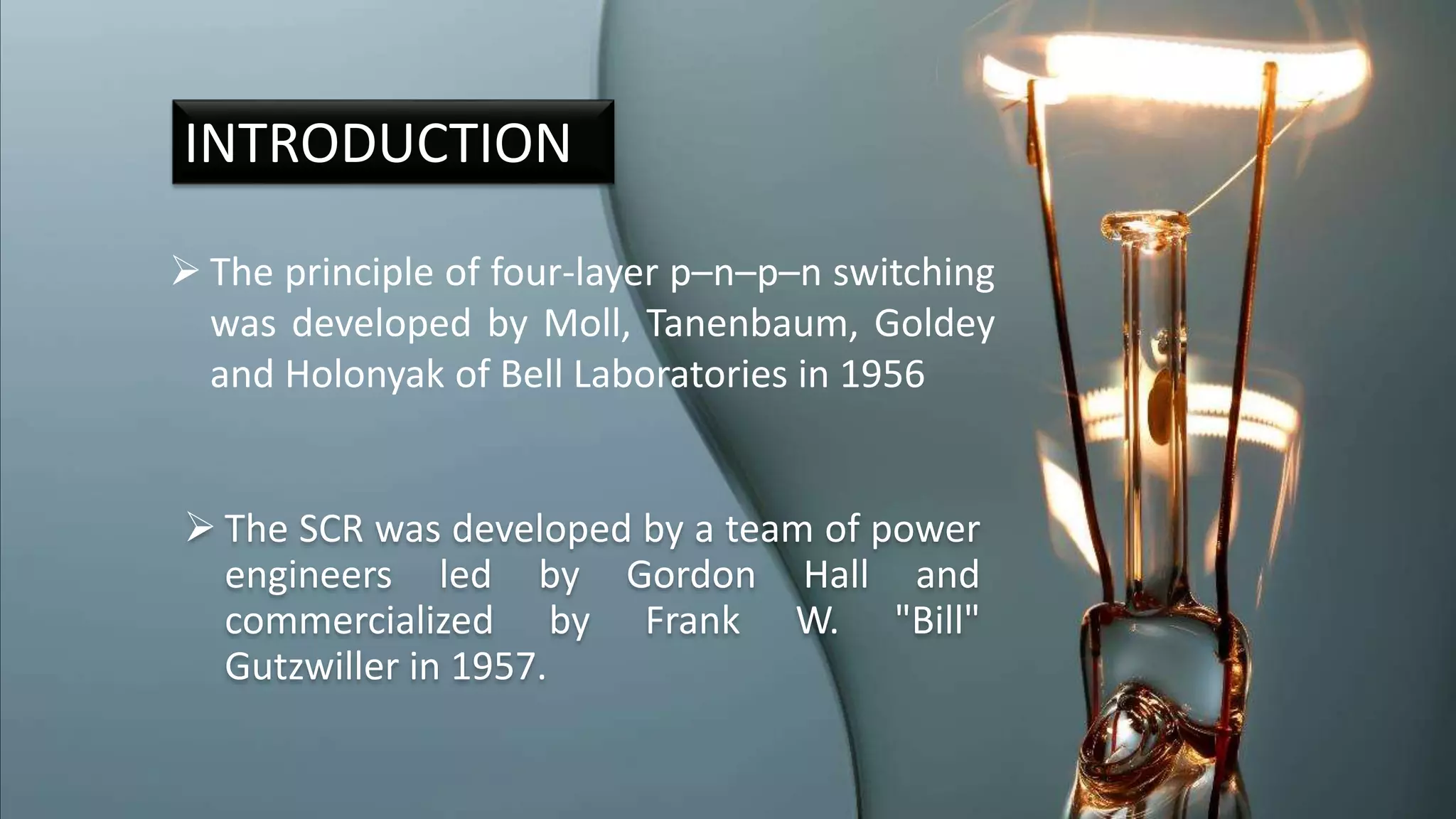
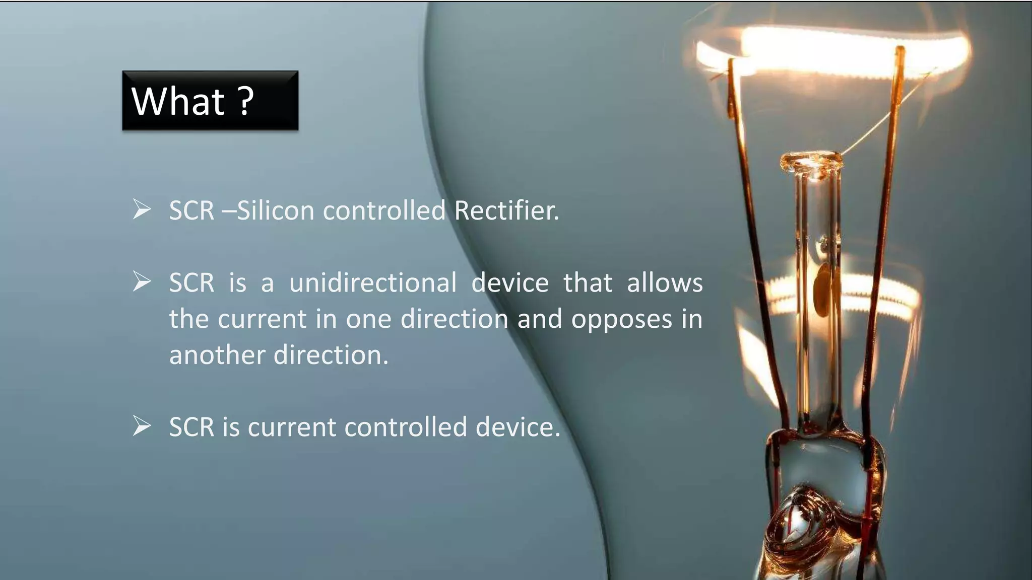
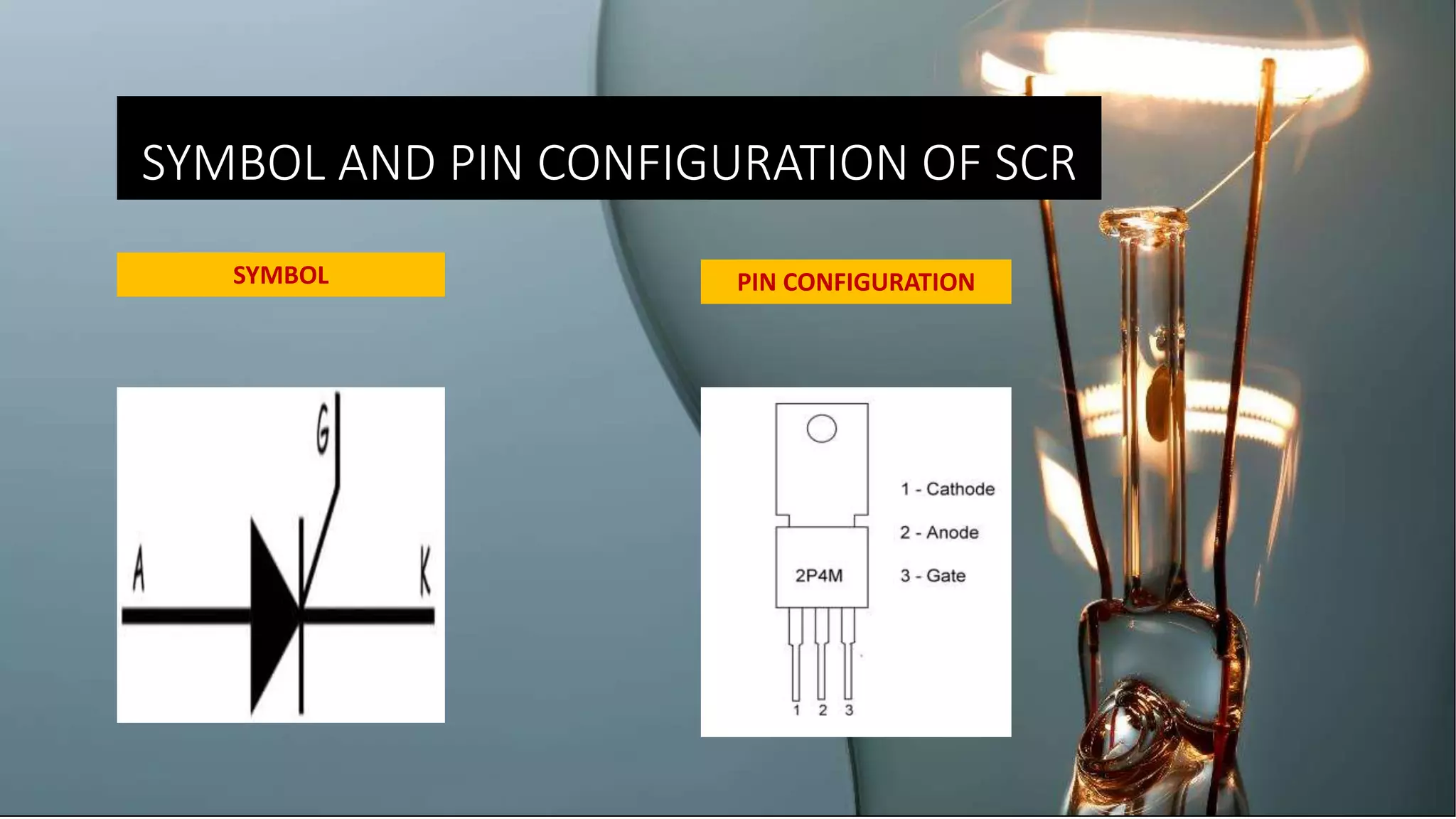
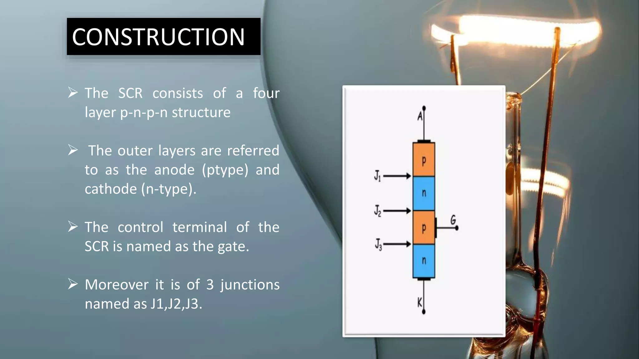
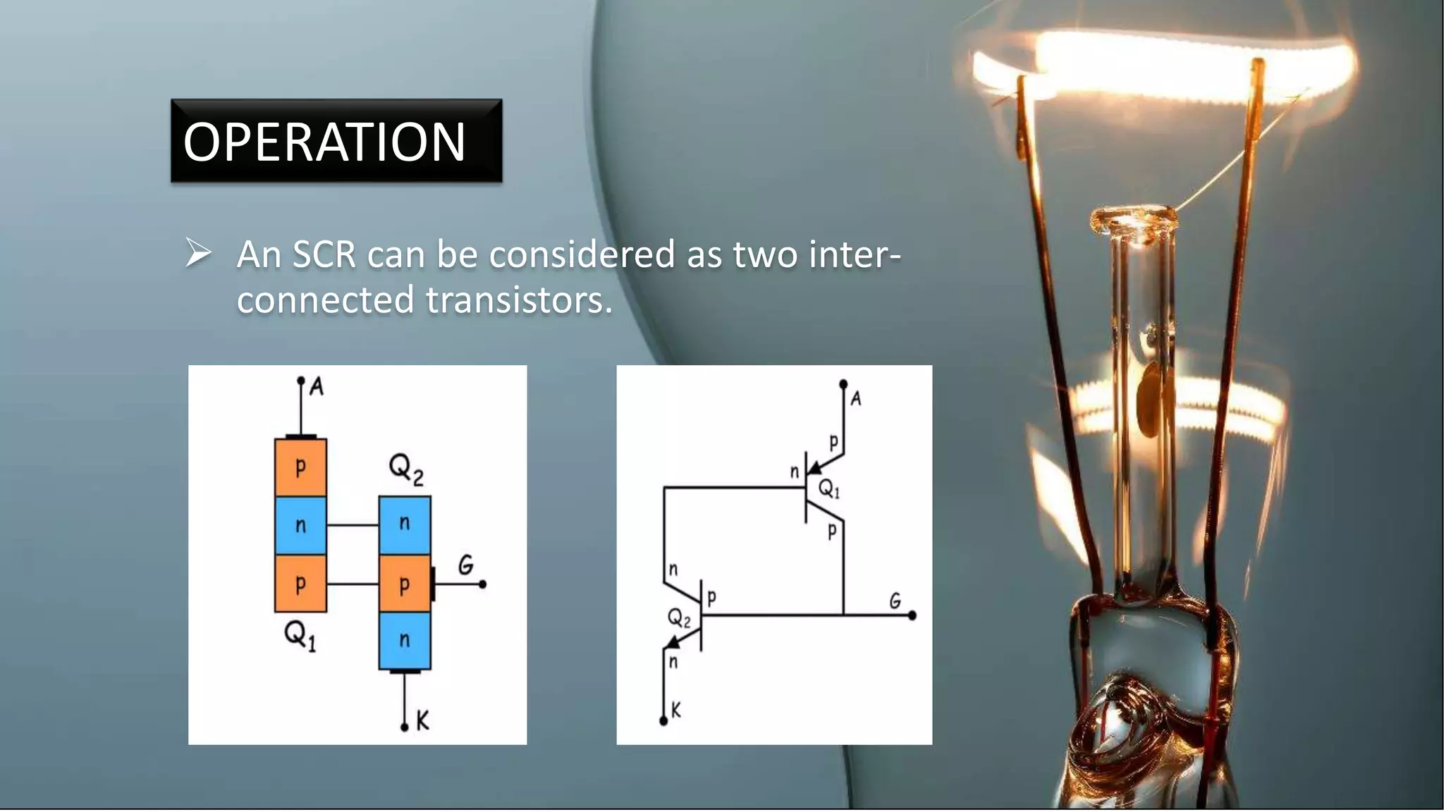
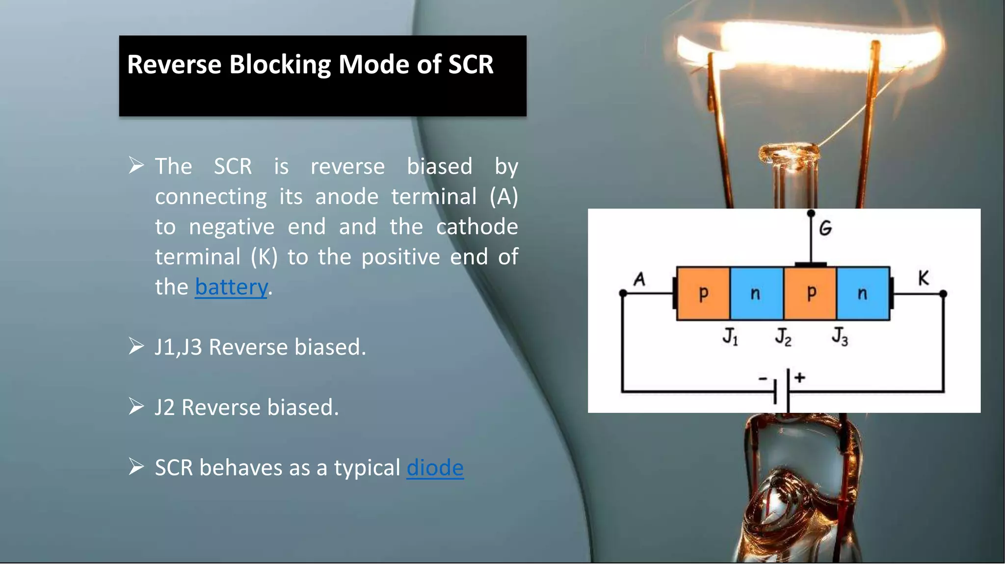
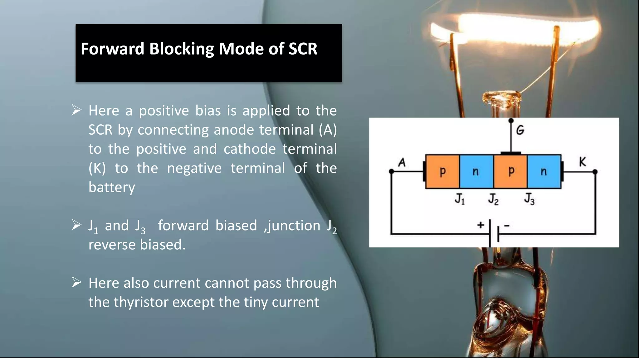
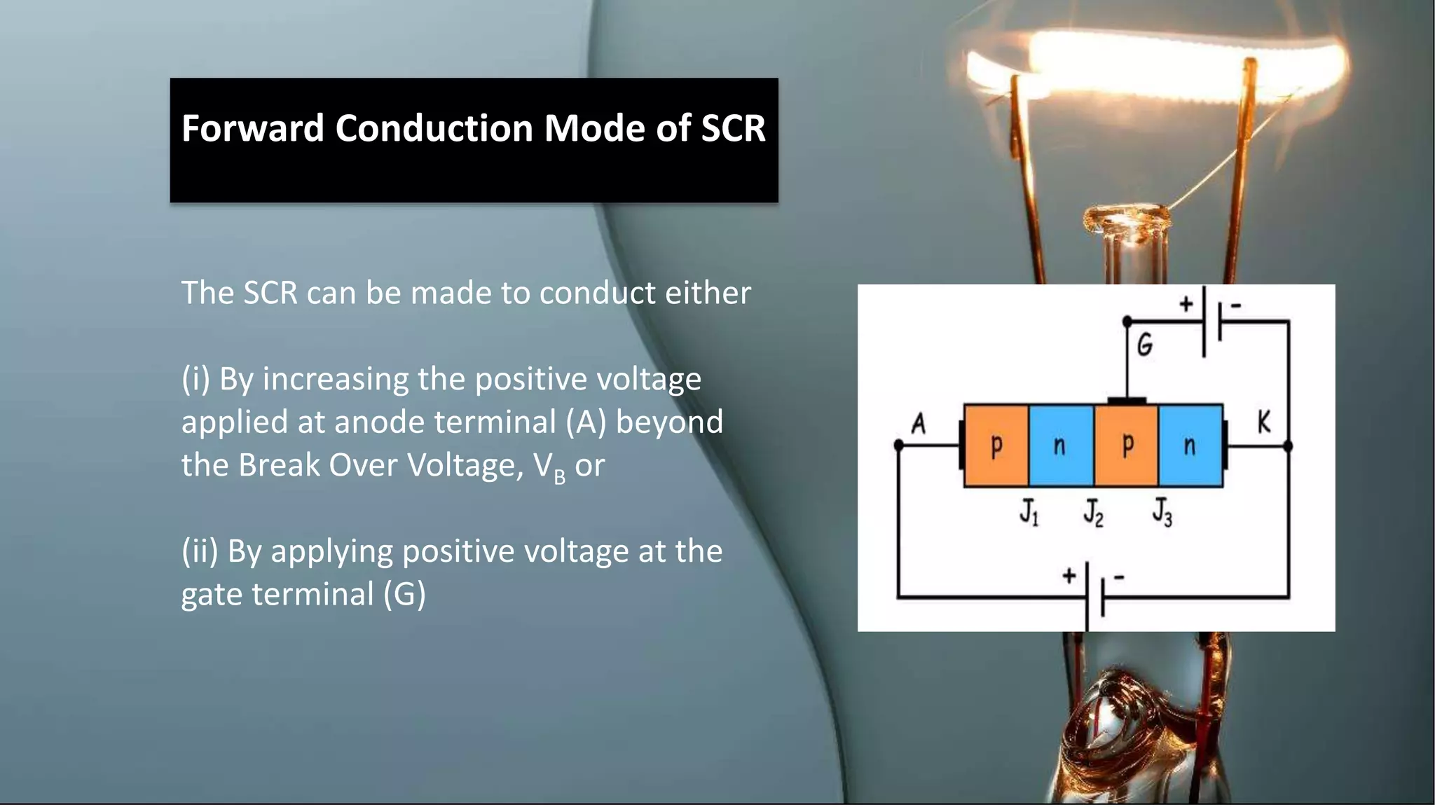
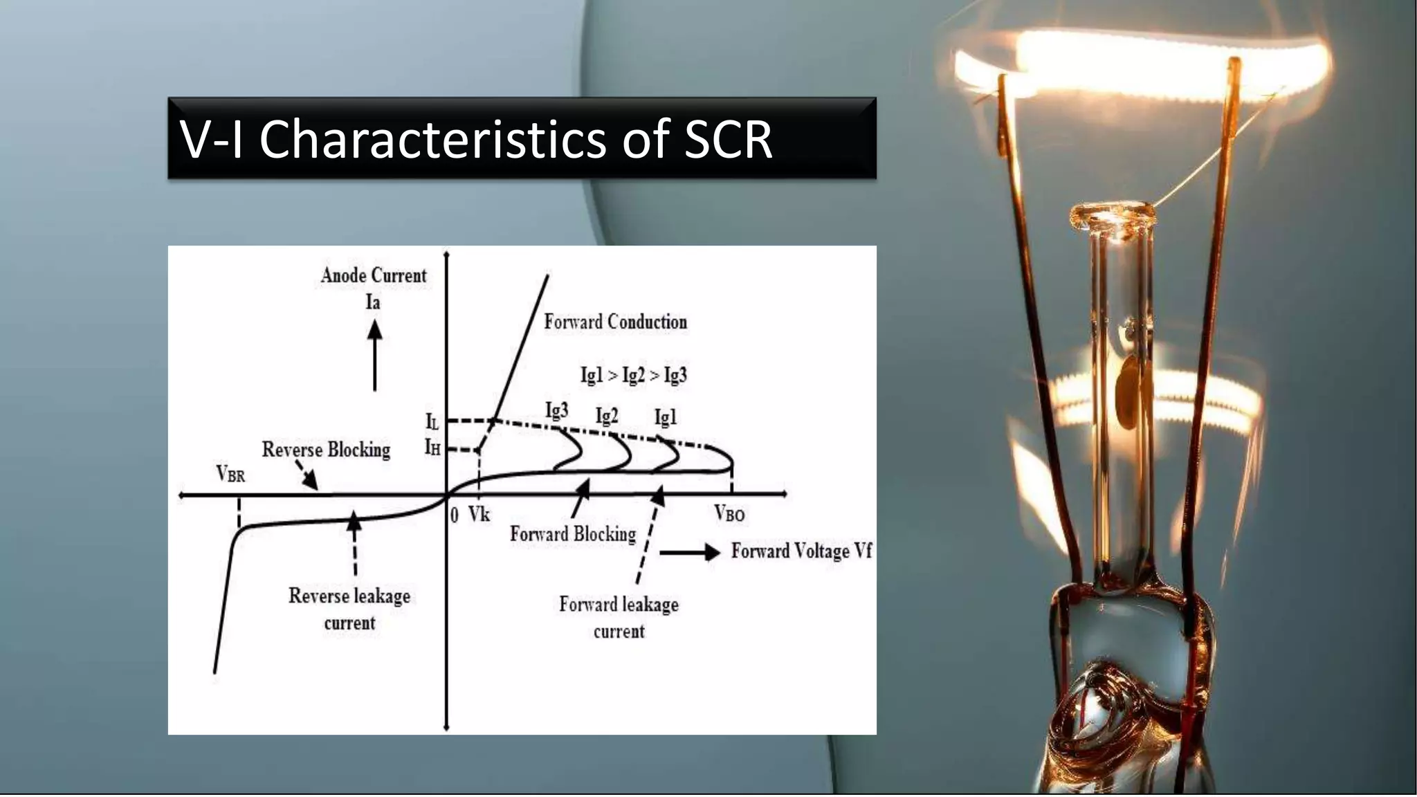
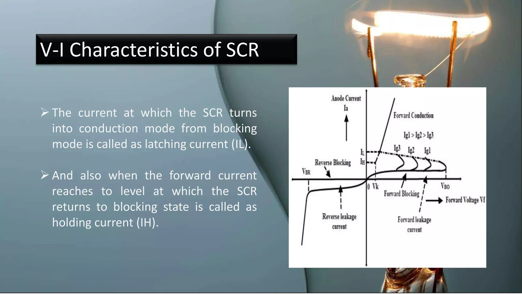
INDUSTRIAL
ELECTRONICS
Mrs.ArulBarathi.K
20/2/2020
THYRISTOR OR SCR
CONTENT
1.Introduction
2.Construction
3.Operation
4.Advantages
5.Disadvantages
6.Projects
Content
 The SCR was developed by a team of power
engineers led by Gordon Hall and
commercialized by Frank W. "Bill"
Gutzwiller in 1957.
INTRODUCTION
 The principle of four-layer p–n–p–n switching
was developed by Moll, Tanenbaum, Goldey
and Holonyak of Bell Laboratories in 1956
What ?
 SCR –Silicon controlled Rectifier.
 SCR is a unidirectional device that allows
the current in one direction and opposes in
another direction.
 SCR is current controlled device.
SYMBOL AND PIN CONFIGURATION OF SCR
PIN CONFIGURATIONSYMBOL
CONSTRUCTION
 The SCR consists of a four
layer p-n-p-n structure
 The outer layers are referred
to as the anode (ptype) and
cathode (n-type).
 The control terminal of the
SCR is named as the gate.
 Moreover it is of 3 junctions
named as J1,J2,J3.
 An SCR can be considered as two inter-
connected transistors.
OPERATION
Reverse Blocking Mode of SCR
 The SCR is reverse biased by
connecting its anode terminal (A)
to negative end and the cathode
terminal (K) to the positive end of
the battery.
 J1,J3 Reverse biased.
 J2 Reverse biased.
 SCR behaves as a typical diode
Forward Blocking Mode of SCR
 Here a positive bias is applied to the
SCR by connecting anode terminal (A)
to the positive and cathode terminal
(K) to the negative terminal of the
battery
 J1 and J3 forward biased ,junction J2
reverse biased.
 Here also current cannot pass through
the thyristor except the tiny current
Forward Conduction Mode of SCR
The SCR can be made to conduct either
(i) By increasing the positive voltage
applied at anode terminal (A) beyond
the Break Over Voltage, VB or
(ii) By applying positive voltage at the
gate terminal (G)
V-I Characteristics of SCR
The current at which the SCR turns
into conduction mode from blocking
mode is called as latching current (IL).
And also when the forward current
reaches to level at which the SCR
returns to blocking state is called as
holding current (IH).
 The SCR (silicon controlled rectifier) can
handle large voltage, current and power.
The Triggering circuit for silicon controlled
rectifier (SCR) is simple.
ADVANTAGES
DISADVANTAGES
:
•In AC circuit, Thyristor needs to be turned on
each cycle.
•SCR takes time to turn on and off.
•The response rate of Thyristor is very low.
Q and A
:
•What is latching current?
•What is holding current?
•V-I characteristics of SCR?
•Operation of SCR?
•Two transistor analogy of SCR

SILICON CONTROLLED RECTIFIER,THYRISTOR,SCR

  • 1.
  • 2.
  • 3.
  • 4.
     The SCRwas developed by a team of power engineers led by Gordon Hall and commercialized by Frank W. "Bill" Gutzwiller in 1957. INTRODUCTION  The principle of four-layer p–n–p–n switching was developed by Moll, Tanenbaum, Goldey and Holonyak of Bell Laboratories in 1956
  • 5.
    What ?  SCR–Silicon controlled Rectifier.  SCR is a unidirectional device that allows the current in one direction and opposes in another direction.  SCR is current controlled device.
  • 6.
    SYMBOL AND PINCONFIGURATION OF SCR PIN CONFIGURATIONSYMBOL
  • 7.
    CONSTRUCTION  The SCRconsists of a four layer p-n-p-n structure  The outer layers are referred to as the anode (ptype) and cathode (n-type).  The control terminal of the SCR is named as the gate.  Moreover it is of 3 junctions named as J1,J2,J3.
  • 8.
     An SCRcan be considered as two inter- connected transistors. OPERATION
  • 9.
    Reverse Blocking Modeof SCR  The SCR is reverse biased by connecting its anode terminal (A) to negative end and the cathode terminal (K) to the positive end of the battery.  J1,J3 Reverse biased.  J2 Reverse biased.  SCR behaves as a typical diode
  • 10.
    Forward Blocking Modeof SCR  Here a positive bias is applied to the SCR by connecting anode terminal (A) to the positive and cathode terminal (K) to the negative terminal of the battery  J1 and J3 forward biased ,junction J2 reverse biased.  Here also current cannot pass through the thyristor except the tiny current
  • 11.
    Forward Conduction Modeof SCR The SCR can be made to conduct either (i) By increasing the positive voltage applied at anode terminal (A) beyond the Break Over Voltage, VB or (ii) By applying positive voltage at the gate terminal (G)
  • 12.
  • 13.
    V-I Characteristics ofSCR The current at which the SCR turns into conduction mode from blocking mode is called as latching current (IL). And also when the forward current reaches to level at which the SCR returns to blocking state is called as holding current (IH).
  • 14.
     The SCR(silicon controlled rectifier) can handle large voltage, current and power. The Triggering circuit for silicon controlled rectifier (SCR) is simple. ADVANTAGES
  • 15.
    DISADVANTAGES : •In AC circuit,Thyristor needs to be turned on each cycle. •SCR takes time to turn on and off. •The response rate of Thyristor is very low.
  • 16.
    Q and A : •Whatis latching current? •What is holding current? •V-I characteristics of SCR? •Operation of SCR? •Two transistor analogy of SCR