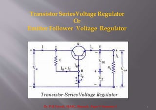
It is also called Transistor Series Voltage
Regulator
1Dr. P.H.Trivedi, SJASC, Bharuch, Paper V Semester 3
The efficiency of Zener regulated power supply
becomes very low when the load current is high.
 Under such conditions a Zener controlled
transistor is always used for maintaining output
voltage constant.
Basically there are two types of Zener controlled
transistor voltage regulators.
Series Voltage Regulators
Shunt Voltage Regulators
2Dr. P.H.Trivedi, SJASC, Bharuch, Paper V Semester 3
Transistor SeriesVoltage Regulator
Or
Emitter Follower Voltage Regulator
3Dr. P.H.Trivedi, SJASC, Bharuch, Paper V Semester 3
This circuit is called a series regulator because collector and emitter terminals
of the transistor are in series with the load, as illustrated in the figure.
This circuit is also called an emitter follower voltage regulator because
transistor Q is connected in emitter follower configuration.
Here, the transistor Q is termed a series-pass transistor.
The unregulated dc supply (or filtered output from the rectifier) is fed to the
input terminals and regulated output voltage Vout is obtained across the load
resistor RL.
Zener diode provides the reference voltage and the transistor acts as a
variable resistor, whose resistance varies with the operating conditions (base
current IB).
The principle of operation of such a regulator is based on the fact that a large
proportion of the change in supply (or input) voltage appears across the
transistor and, therefore output voltage tends to remain constant.
4Dr. P.H.Trivedi, SJASC, Bharuch, Paper V Semester 3
 Keeping in mind the polarities of different voltages we
have
Vout = Vz – VBE
 The base voltage of the transistor remains almost
constant being equal to that aross the Zener diode, Vz
5Dr. P.H.Trivedi, SJASC, Bharuch, Paper V Semester 3
1) Let the supply (or input) voltage increase which will
cause the output voltage Vout to increase.
 An increase in output voltage Vout will result in decrease
of VBE because Vz is fixed and decrease in VBE will reduce
the level of conduction.
 This will lead to increase in the collector-emitter
resistance of the transistor causing an increase in collector
to emitter voltage and as a result the output voltage will be
reduced.
 Thus output voltage will remain constant.
6Dr. P.H.Trivedi, SJASC, Bharuch, Paper V Semester 3
Similar explanation can be given for decrease in supply voltage.
2) Now let us consider the effect of change in load on the output
voltage — say current is increased by decrease in RL.
 Under such a situation the output voltage Vout tends to fall and,
therefore, VBE tends to increase.
 As a result the conduction level of the transistor will increase
leading to decrease in the collector-emitter resistance.
 This decrease in the collector-emitter resistance of the transistor
will cause the slight increase in input current to compensate for the
decrease in RL.
 The output voltage being equal to IL,
RL remains almost constant.
N.B. Similar explanation will hold true for increase in RL also.
7Dr. P.H.Trivedi, SJASC, Bharuch, Paper V Semester 3
 The changes in Zener current are reduced by a factor β and
thus the effect of Zener effect is greatly reduced and much
more stabilized output is obtained.
 Output voltage from a series regulator
Vout = (Vz – VBE)
and maximum load current IL(max) can be the maximum
emitter current that the transistor Q is capable of passing.
 For a 2N 3055 transistor load current IL could be 15 A.
 When load current IL is zero, the current drawn from the
supply is approximately (Iz + IC(min).)
 The Zener regulator has to supply only the base current of
the transistor. The emitter follower voltage regulator is,
therefore, much more efficient than a simple Zener
regulator.
8Dr. P.H.Trivedi, SJASC, Bharuch, Paper V Semester 3
 The output voltage cannot be maintained absolutely constant
because both VBE and Vz decrease with the increase in room
temperature.
 Further, VBE increases slightly with the increase in load.
 The output voltage cannot be changed as there is no provision for
it in the circuit.
 It cannot provide good regulation at high currents because of
small amplification provided by one transistor.
 It has poor regulation and ripple suppression with respect to
input variations as compared to other regulators.
 The power dissipation of a pass transistor is large because it is
equal to VccIc and almost all variation appears at VCE and the load
current is approximately equal to collector current.
 Thus for heavy load currents pass transistor has to dissipate a lot
of power and, therefore, becoming hot.
9Dr. P.H.Trivedi, SJASC, Bharuch, Paper V Semester 3
Because of the limitations discussed
application of this regulator is limited to
“low output voltages”
10Dr. P.H.Trivedi, SJASC, Bharuch, Paper V Semester 3

Emitter follower regulator

  • 1.
    It is alsocalled Transistor Series Voltage Regulator 1Dr. P.H.Trivedi, SJASC, Bharuch, Paper V Semester 3
  • 2.
    The efficiency ofZener regulated power supply becomes very low when the load current is high.  Under such conditions a Zener controlled transistor is always used for maintaining output voltage constant. Basically there are two types of Zener controlled transistor voltage regulators. Series Voltage Regulators Shunt Voltage Regulators 2Dr. P.H.Trivedi, SJASC, Bharuch, Paper V Semester 3
  • 3.
    Transistor SeriesVoltage Regulator Or EmitterFollower Voltage Regulator 3Dr. P.H.Trivedi, SJASC, Bharuch, Paper V Semester 3
  • 4.
    This circuit iscalled a series regulator because collector and emitter terminals of the transistor are in series with the load, as illustrated in the figure. This circuit is also called an emitter follower voltage regulator because transistor Q is connected in emitter follower configuration. Here, the transistor Q is termed a series-pass transistor. The unregulated dc supply (or filtered output from the rectifier) is fed to the input terminals and regulated output voltage Vout is obtained across the load resistor RL. Zener diode provides the reference voltage and the transistor acts as a variable resistor, whose resistance varies with the operating conditions (base current IB). The principle of operation of such a regulator is based on the fact that a large proportion of the change in supply (or input) voltage appears across the transistor and, therefore output voltage tends to remain constant. 4Dr. P.H.Trivedi, SJASC, Bharuch, Paper V Semester 3
  • 5.
     Keeping inmind the polarities of different voltages we have Vout = Vz – VBE  The base voltage of the transistor remains almost constant being equal to that aross the Zener diode, Vz 5Dr. P.H.Trivedi, SJASC, Bharuch, Paper V Semester 3
  • 6.
    1) Let thesupply (or input) voltage increase which will cause the output voltage Vout to increase.  An increase in output voltage Vout will result in decrease of VBE because Vz is fixed and decrease in VBE will reduce the level of conduction.  This will lead to increase in the collector-emitter resistance of the transistor causing an increase in collector to emitter voltage and as a result the output voltage will be reduced.  Thus output voltage will remain constant. 6Dr. P.H.Trivedi, SJASC, Bharuch, Paper V Semester 3
  • 7.
    Similar explanation canbe given for decrease in supply voltage. 2) Now let us consider the effect of change in load on the output voltage — say current is increased by decrease in RL.  Under such a situation the output voltage Vout tends to fall and, therefore, VBE tends to increase.  As a result the conduction level of the transistor will increase leading to decrease in the collector-emitter resistance.  This decrease in the collector-emitter resistance of the transistor will cause the slight increase in input current to compensate for the decrease in RL.  The output voltage being equal to IL, RL remains almost constant. N.B. Similar explanation will hold true for increase in RL also. 7Dr. P.H.Trivedi, SJASC, Bharuch, Paper V Semester 3
  • 8.
     The changesin Zener current are reduced by a factor β and thus the effect of Zener effect is greatly reduced and much more stabilized output is obtained.  Output voltage from a series regulator Vout = (Vz – VBE) and maximum load current IL(max) can be the maximum emitter current that the transistor Q is capable of passing.  For a 2N 3055 transistor load current IL could be 15 A.  When load current IL is zero, the current drawn from the supply is approximately (Iz + IC(min).)  The Zener regulator has to supply only the base current of the transistor. The emitter follower voltage regulator is, therefore, much more efficient than a simple Zener regulator. 8Dr. P.H.Trivedi, SJASC, Bharuch, Paper V Semester 3
  • 9.
     The outputvoltage cannot be maintained absolutely constant because both VBE and Vz decrease with the increase in room temperature.  Further, VBE increases slightly with the increase in load.  The output voltage cannot be changed as there is no provision for it in the circuit.  It cannot provide good regulation at high currents because of small amplification provided by one transistor.  It has poor regulation and ripple suppression with respect to input variations as compared to other regulators.  The power dissipation of a pass transistor is large because it is equal to VccIc and almost all variation appears at VCE and the load current is approximately equal to collector current.  Thus for heavy load currents pass transistor has to dissipate a lot of power and, therefore, becoming hot. 9Dr. P.H.Trivedi, SJASC, Bharuch, Paper V Semester 3
  • 10.
    Because of thelimitations discussed application of this regulator is limited to “low output voltages” 10Dr. P.H.Trivedi, SJASC, Bharuch, Paper V Semester 3