SlideShare a Scribd company logo
Dr.R. GANESAMOORTHY.B.E.,M.E.,Ph.d.
Professor –Mechanical Engineering
Saveetha Engineering College
Tandalam
Chennai.
24-Sep-18 1Dr.RGM PROF/MECH / UNIT 1 ENGG GRAPHICS
Definition
Engineering graphics is the language for
Effective Communication among engineers which
elaborates the details of any component,
structure or circuit at its initial drawing through
drawing.
24-Sep-18 2Dr.RGM PROF/MECH / UNIT 1 ENGG GRAPHICS
DRAFTING TOOLS
❖ Drawing Board
❖ Mini drafter or T- square
❖ Drawing Instrument box
❖ Drawing Pencils
❖ Eraser
❖ Templates
❖ Set squares
❖ Protractor
❖Scale Set
❖French curves
❖Drawing clips
❖Duster piece of cloth(or)
brush
❖Sand-paper (or) Emery
sheet block
❖Drawing sheet
24-Sep-18 3Dr.RGM PROF/MECH / UNIT 1 ENGG GRAPHICS
The following are the various drafting tools used in
engineering graphics.
DRAFTING TOOLS
24-Sep-18 Dr.RGM PROF/MECH / UNIT 1 ENGG GRAPHICS 4
24-Sep-18 Dr.RGM PROF/MECH / UNIT 1 ENGG GRAPHICS 5
Drawing Sheet
Designatio
n
Dimension, mm
A0 841 x 1189
A1 594 x 841
A2 420 x 594
A3 297 x 420
A4 210 x 297
Lines
• Visible Outlines, Visible ,Edges- Continuous wide lines
• Dimension Lines - Continuous narrow Lines
• Extension Lines - Continuous narrow Lines
• Construction Lines - Continuous narrow Lines
• Hatching / Section Lines - Continuous narrow Lines
• Guide Lines - Continuous narrow Lines
• Break Lines - Continuous Narrow Freehand Lines
• Break Lines - Continuous Narrow Lines With Zigzags
• Dashed Narrow Lines - Dashed Narrow Lines
• Centre Lines - Long-Dashed Dotted Narrow Lines
• Cutting Plane Lines - long-dashed dotted narrow line
• Border Lines - Continuous wide lines
24-Sep-18 Dr.RGM PROF/MECH / UNIT 1 ENGG GRAPHICS 6
Types of Lines and their applications
1.Continuous narrow line-Dimension lines, Extension
lines, Leader lines, Reference lines, Short centre lines,
Projection lines, Hatching, Construction lines, Guide lines,
Outlines of revolved sections ,Imaginary lines of
intersection
2.Continuous narrow freehand line-Preferably manually
represented termination of partial or interrupted views,
Cuts and sections, if the limit is not a line of symmetry or
a Centre line·
24-Sep-18 Dr.RGM PROF/MECH / UNIT 1 ENGG GRAPHICS 7
Types of Lines and their applications
Conti........
3.Continuous narrow line with zigzags -Preferably
mechanically represented termination of partial or
interrupted views. cuts and sections, if the limit is not a
line of symmetry or a centre line .
4.Continuous wide line -Visible edges, visible outlines,
Main representations in diagrams, maps. flow charts.
5.Dashed narrow line -Hidden edges ,Hidden outlines
24-Sep-18 Dr.RGM PROF/MECH / UNIT 1 ENGG GRAPHICS 8
Types of Lines and their applications
Conti........
6.Long-dashed dotted narrow line -Centre lines /
Axes. Lines of symmetry, Cutting planes
7. Long-dashed dotted wide line-Cutting planes at
the ends and changes of direction outlines of visible
parts situated front of cutting plane
24-Sep-18 Dr.RGM PROF/MECH / UNIT 1 ENGG GRAPHICS 9
Dimensioning
Dimensioning provided through the distances between
the surfaces, location of holes, nature of surface finish,
type of material, etc.
Elements of dimensioning
1.Dimension line
2.Leader line
3.Origin indication
4.Dimension
5.Projection or extension line
6. Dimension line termination
24-Sep-18 Dr.RGM PROF/MECH / UNIT 1 ENGG GRAPHICS 10
Principles of Dimensioning
I. All dimensional information necessary to describe a
component clearly and completely shall be written
directly on a drawing.
2. Each feature shall be dimensioned once only on a
drawing, i.e., dimension marked in one view need
not be repeated in another view.
24-Sep-18 Dr.RGM PROF/MECH / UNIT 1 ENGG GRAPHICS 11
Principles of Dimensioning
Conti.....
3. Dimension should be placed on the view where the
shape is best seen (Fig.)
4. As far as possible, dimensions should be expressed
in one unit only preferably in millimetres, without
showing the unit symbol (mm).
24-Sep-18 Dr.RGM PROF/MECH / UNIT 1 ENGG GRAPHICS 12
Principles of Dimensioning
Conti.....
5. As far as possible dimensions should be placed
outside the view (Fig.).
6. Dimensions should be taken from visible outlines
rather than from hidden lines (Fig.)
24-Sep-18 Dr.RGM PROF/MECH / UNIT 1 ENGG GRAPHICS 13
Principles of Dimensioning
Conti.....
7. No gap should be left between the feature and the
start of the extension line(Fig.).
8. Crossing of centre lines should be done by a long
dash and not a short dash (Fig.).
24-Sep-18 Dr.RGM PROF/MECH / UNIT 1 ENGG GRAPHICS 14
Methods of Indicating Dimensions
Method - 1 (Aligned method).
Method - 2 (Uni -directional method)
24-Sep-18 Dr.RGM PROF/MECH / UNIT 1 ENGG GRAPHICS 15
Arrangement of Dimensions
They are arranged in three ways.
1. Chain dimensioning 2. Parallel dimensioning
3. Combined dimensioning.
24-Sep-18 Dr.RGM PROF/MECH / UNIT 1 ENGG GRAPHICS 16
24-Sep-18 Dr.RGM PROF/MECH / UNIT 1 ENGG GRAPHICS 17
Set of Scales
Scales are used to make drawing of the objects to
proportionate size desired. These are made of wood,
steel or plastic.
24-Sep-18 Dr.RGM PROF/MECH / UNIT 1 ENGG GRAPHICS 17
M1 M2 M3 M4 M5 M6 M7 M8
Scale on one
edge
1:1 1:25 1:10 1:50 1:200 1:300 1:400 1:1000
Scale on other
edge
1:2 1:5 1:20 1:100 1:500 1:600 1:800 1:2000Scales for use on technical drawings(IS: 46-
1988)
Category Category Recommended scales
Enlargeme
nt scales
50 : 1
5 : 1
20 : 1
2 : 1
10 : 1
Full size 1 : 1
Reduction
scales
1 : 2
1 : 20
1 : 200
1 : 2000
1 : 5
1 : 50
1 : 500
1 : 5000
1 : 10
1 : 100
1 : 1000
1 : 10000
Scale
Definition :
Scale is defined as the ratio of the linear dimension of
an element of an object as represented in the original
drawing to the linear dimension of the same element of
the object itself.
Full size scale
If we show the actual length of an object on a drawing,
then the scale used is called full size scale.
24-Sep-18 Dr.RGM PROF/MECH / UNIT 1 ENGG GRAPHICS 18
Scale Conti…..
Reducing scale
If we reduce the actual length of an object so as to
accommodate that object on drawing, then scale used is
called reducing scale.
Enlarging scale
Drawings of smaller machine parts, mechanical instruments,
watches, etc. are made larger than their real size. These are
said to be drawn in an increasing or enlarging scale.
24-Sep-18 Dr.RGM PROF/MECH / UNIT 1 ENGG GRAPHICS 19
Representative Fraction (R.F)
The ratio of the drawing of an object to its actual size is
Called the representative fraction, usually referred to as
R.F.
R.F=Drawing of an object/It’s actual size(in same units)
For reducing scale, the drawings will have R.F. values of
Less than unity.
if 1 cm on drawing represents
1 m length of an object.
24-Sep-18 Dr.RGM PROF/MECH / UNIT 1 ENGG GRAPHICS 20
Representative Fraction (R.F) conti....
Increasing or enlarging scale, the R.F values will be
Greater than unity.
For example, when 1 mm length of an object is shown by
a length of 1cm on the drawing
24-Sep-18 Dr.RGM PROF/MECH / UNIT 1 ENGG GRAPHICS 21
Types of Scales
Types of Scales
1.Simple scales
2. Diagonal scales
3. Vernier scales
Simple scales
A plain scale is simply a line, which is divided into a
suitable number of equal parts, the first of which is further
sub-divided into small parts.
It is used to represent either two units or a unit and its
fraction such as km, m and dm, etc.
24-Sep-18 Dr.RGM PROF/MECH / UNIT 1 ENGG GRAPHICS 22
Types of Scales Conti.....
Plain scales , Diagonal Scales, Vernier Scale
Plain scales are used to read lengths in two units such as
metres and decimetres or to read the accuracy correct to
first decimal.
Diagonal scales are used to represent either three units
of measurements such as metres, decimetres, centimetres
or to read to the accuracy correct to two decimals.
The diagonal scales, vernier scales are used to read very
Small units with accuracy.
They are used, when a diagonal Scale is inconvenient to
use due to lack of space.
24-Sep-18 Dr.RGM PROF/MECH / UNIT 1 ENGG GRAPHICS 23
Types of Scales Conti.....
Vernier scale
A vernier Scale consists of two parts, i.e., Main scale
and a vernier.
The main scale is a Plain scale divided into minor
divisions.
The vernier is also a scale used along with the main
scale to read the third unit, which is the fraction of
the second unit on the main scale.
24-Sep-18 Dr.RGM PROF/MECH / UNIT 1 ENGG GRAPHICS 24
Types of Scales Conti.....
Least count: Least count the smallest distance
that can be measured accurately by the vernier
scale and is the vernier scale and is the difference
between a main scale division and a vernier scale
division.
Types of Verniers:
1. Forward vernier or direct vernier
2. Backward vernier or retrograde vernier
24-Sep-18 Dr.RGM PROF/MECH / UNIT 1 ENGG GRAPHICS 25
Lettering
Technical lettering is the process of forming letters,
numerals, and other characters in technical drawing. It is
used to describe, or provide detailed specifications for, an
object.
24-Sep-18 Dr.RGM PROF/MECH / UNIT 1 ENGG GRAPHICS 26
Characteristic Parameter Ratio Dimensions(mm)
Lettering Height
(Height of capitals)
h (14/14)h 2.5 3.5 5 7 10 14 20
Height of lower case
letters
(without stem or tail)
c (10/14)h - 2.5 3.5 5 7 10 14
Spacing between
characters
a (2/14)h 0.35 0.5 0.7 1 1.4 2 2.8
Minimum spacing of base
characters
b (20/14)h 3.5 5 7 10 14 20 28
Minimum spacing
between words
e (6/14)h 1.05 1.5 2.1 3 4.2 6 8.4
Lettering Conti.....
Characteristic Parameter Ratio Dimensions(mm)
Lettering Height
(Height of capitals)
h (10/10)h 2.5 3.5 5 7 10 14 20
Height of lower case letters
(without stem or tail)
c (7/10)h - 2.5 3.5 5 7 10 14
Spacing between
characters
a (2/10)h 0.5 0.7 1 1.4 2 2.8 4
Minimum spacing of base
characters
b (14/10)h 3.5 5 7 10 14 20 28
Minimum spacing between
words
e (6/10)h 1.5 2.1 3 4.2 6 8.4 12
Thickness of lines d (1/10)h 0.25 0.35 0.5 0.7 1 1.4 2
24-Sep-18 Dr.RGM PROF/MECH / UNIT 1 ENGG GRAPHICS 27
Geometric Construction
Drawing consists of construction of primitive geometric
forms viz. points, lines and planes that serve at building
blocks . The use of lines for obtaining the drawing of
planes
24-Sep-18 Dr.RGM PROF/MECH / UNIT 1 ENGG GRAPHICS 28
Geometric Construction Conti........
Solids are obtained by combination of planes. Plane
surfaces of simple solids are shown in figure.
24-Sep-18 Dr.RGM PROF/MECH / UNIT 1 ENGG GRAPHICS 29
To divide a straight line into a given
number of equal parts say 5. Construction
24-Sep-18 Dr.RGM PROF/MECH / UNIT 1 ENGG GRAPHICS 30
1. Draw AC at any angle θ to AB.
2. Construct the required number of equal parts of
convenient length on AC like 1,2,3.
3. Join the last point 5 to B
4. Through 4, 3, 2, 1 draw lines parallel to 5B to intersect
AB at 4',3',2' and 1'.
24-Sep-18 Dr.RGM PROF/MECH / UNIT 1 ENGG GRAPHICS 31
1. Draw a line AB and AC making the given angle.
2. With centre A and any convenient radius R draw an
arc intersecting the sides at D and E.
3. With centers D and E and radius larger than half the
chord length DE, draw arcs intersecting at F
4. Join AF, <BAF = <PAC.
To bisect a given angle Construction
To inscribe a square in a given
circle Construction
1. With centre 0, draw a circle of diameter D.
2. Through the centre 0, draw two diameters, say AC and
BD at right angle to each other.
3. Join A-B, B-C, C- D, and D-A. ABCD is the required
square.
24-Sep-18 Dr.RGM PROF/MECH / UNIT 1 ENGG GRAPHICS 32
To inscribe a hexagon in a given
circle.
By using a set-square or mini-draughter
1. With centre 0 and radius R draw the given circle.
2. Draw any diameter AD to the circle.
3. Using 30° - 60° set-square and through the point A draw lines AI, A2 at an
angle 60° with AD, intersecting the circle at B and F respectively.
4. Using 30° - 60° and through the point D draw lines Dl, D2 at an angle 60° with
DA, intersecting the circle at C and E respectively.
By joining A, B, C, D, E, F, and A the required hexagon is obtained.
24-Sep-18 Dr.RGM PROF/MECH / UNIT 1 ENGG GRAPHICS 33
To inscribe a hexagon in a given
circle.
By using compass
1. With centre 0 and radius R draw the given circle.
2. Draw any diameter AD to the circle.
3. With centres A and D and radius equal to the radius of the circle draw
arcs intersecting the circles at B, F, C and E respectively.
4. ABC D E F is the required hexagon.
24-Sep-18 Dr.RGM PROF/MECH / UNIT 1 ENGG GRAPHICS 34
To circumscribe a hexagon on a given
circle of radius R construction
1. With centre 0 and radius R draw the given circle.
2. Using 60° position of the mini draughter or 300-
600set square, circumscribe the hexagon as shown.
24-Sep-18 Dr.RGM PROF/MECH / UNIT 1 ENGG GRAPHICS 35
To construct a hexagon, given the
length of the side
(a)Using set square
1. Draw a line AB equal to the side of the hexagon.
2. Using 30° - 60° set-square draw lines AI, A2, and BI,B2.
3. Through 0, the point of intersection between the lines
A2 at D and B2 at E.
4. Join D,E
5. ABC D E F is the required hexagon.
24-Sep-18 Dr.RGM PROF/MECH / UNIT 1 ENGG GRAPHICS 36
To construct a hexagon, given the
length of the side
(b) By using compass
1. Draw a line AB equal to the of side of the hexagon.
2. with centres A and B and radius AB, draw arcs
intersecting at 0, the centre of the hexagon.
3. With centres 0 and B and radius OB (=AB) draw arcs
intersecting at C.
4. Obtain points D, E and F in a similar manner.
24-Sep-18 Dr.RGM PROF/MECH / UNIT 1 ENGG GRAPHICS 37
To construct a regular polygon
(say a pentagon) given the length
of the side.
1. Draw a line AB equal to the side and extend to P such that AB = BP
2. Draw a semicircle on AP and divide it into 5 equal parts by trial and error.
3. Join B to second division
4. Irrespective of the number of sides of the polygon B is always joined to
the second division.
5. Draw the perpendicular bisectors of AB and B2 to intersect at O.
6. Draw a circle with 0 as centre and OB as radius.
7. With AB as radius intersect the circle
successively at D and E.Then join CD.
DE and EA.
24-Sep-18 Dr.RGM PROF/MECH / UNIT 1 ENGG GRAPHICS 38
To construct a regular polygon
(say a hexagon) given the side AB
– alternate Method.
1. Steps 1 to 3 are same as above
2. Join B- 3, B-4, B-5 and produce them.
3. With 2 as centre and radius AB intersect the line B, 3
produced at D. Similarly get the point E and F.
4. Join 2- D, D-E, E-F and F-A
to get the required hexagon.
24-Sep-18 Dr.RGM PROF/MECH / UNIT 1 ENGG GRAPHICS 39
To construct a pentagon, given
the length of side.
1. Draw a line AB equal to the given length of side.
2. Bisect AB at P.
3. Draw a line BQ equal to AB in length and perpendicular to AB.
4. With centre P and radius PQ, draw an arc intersecting AB produced at R.
AR is equal to the diagonal length of the pentagon.
5. With centres A and B and radii AR and AB respectively draw arcs
intersecting at C.
6. With centres A and B and radius AR draw arcs
intersecting at D.
7. With centres A and B and radii AB and AR
respectively draw arcs intersecting at E.
ABCDE is the required pentagon.
24-Sep-18 Dr.RGM PROF/MECH / UNIT 1 ENGG GRAPHICS 40
By included angle method
1.Draw a line AB equal to the length of the given side.
2.Draw a line B 1 such that <AB 1 = 108° (included angle)
3.Mark C on B1 such that BC = AB
4.Repeat steps 2 and 3 and complete the pentagon ABCDE
24-Sep-18 Dr.RGM PROF/MECH / UNIT 1 ENGG GRAPHICS 41
To construct a pentagon, given the
length of side.

More Related Content

What's hot

Introduction to engineering graphics
Introduction to engineering graphicsIntroduction to engineering graphics
Introduction to engineering graphics
Suraj Meshram
 
Surface texture
Surface textureSurface texture
Surface texture
GAURAVBHARDWAJ160
 
ppt on Sheet metal process
ppt on Sheet metal processppt on Sheet metal process
ppt on Sheet metal process
sumant99
 
Milling Machines
Milling MachinesMilling Machines
Milling Machines
ujjwal Mania
 
BE sem 1 Engineering Graphics(E.G.) full course ppt
BE sem 1 Engineering Graphics(E.G.) full course pptBE sem 1 Engineering Graphics(E.G.) full course ppt
BE sem 1 Engineering Graphics(E.G.) full course ppt
Dhruv Parekh
 
Chapter 7 measurement of surface finish
Chapter 7 measurement of surface finishChapter 7 measurement of surface finish
Chapter 7 measurement of surface finish
VISHALM580
 
projections - engineering drawing
projections - engineering drawing projections - engineering drawing
projections - engineering drawing
Krishna Gali
 
Drawing presentation 2015 2016
Drawing presentation 2015 2016Drawing presentation 2015 2016
Drawing presentation 2015 2016
muralbe1
 
Drawing Instruments and Accessories
Drawing Instruments and AccessoriesDrawing Instruments and Accessories
Drawing Instruments and Accessories
MOKSHIT TECH
 
Basics of engineering drawing by Rishabh Natholia
Basics of engineering drawing by Rishabh NatholiaBasics of engineering drawing by Rishabh Natholia
Basics of engineering drawing by Rishabh Natholia
RISHABH NATHOLIA
 
Sectioning notes ppt
Sectioning notes pptSectioning notes ppt
Sectioning notes ppt
musadoto
 
signature of single point cutting tool
signature of single point cutting toolsignature of single point cutting tool
signature of single point cutting tool
Vaibhav Kadu
 
press tool, jigs & fixtures, gear and thread manufacturing,manufacturing pro...
 press tool, jigs & fixtures, gear and thread manufacturing,manufacturing pro... press tool, jigs & fixtures, gear and thread manufacturing,manufacturing pro...
press tool, jigs & fixtures, gear and thread manufacturing,manufacturing pro...
Prof.Mayur Modi
 
punch and die design-1.pptx
punch and die design-1.pptxpunch and die design-1.pptx
punch and die design-1.pptx
AmitMittal444758
 
Machining Process
Machining ProcessMachining Process
Machining Process
Kunj Soni
 
Engineering Graphics - Introduction PPT
Engineering Graphics - Introduction PPTEngineering Graphics - Introduction PPT
Engineering Graphics - Introduction PPT
balajijayavel
 
Metrology of threads
Metrology of threadsMetrology of threads
Metrology of threads
nilesh sadaphal
 
Jigs and Fixture
Jigs and FixtureJigs and Fixture
Jigs and Fixture
Kondayya Devarakonda
 

What's hot (20)

Introduction to engineering graphics
Introduction to engineering graphicsIntroduction to engineering graphics
Introduction to engineering graphics
 
Surface texture
Surface textureSurface texture
Surface texture
 
ppt on Sheet metal process
ppt on Sheet metal processppt on Sheet metal process
ppt on Sheet metal process
 
Milling Machines
Milling MachinesMilling Machines
Milling Machines
 
BE sem 1 Engineering Graphics(E.G.) full course ppt
BE sem 1 Engineering Graphics(E.G.) full course pptBE sem 1 Engineering Graphics(E.G.) full course ppt
BE sem 1 Engineering Graphics(E.G.) full course ppt
 
Chapter 7 measurement of surface finish
Chapter 7 measurement of surface finishChapter 7 measurement of surface finish
Chapter 7 measurement of surface finish
 
projections - engineering drawing
projections - engineering drawing projections - engineering drawing
projections - engineering drawing
 
Drawing presentation 2015 2016
Drawing presentation 2015 2016Drawing presentation 2015 2016
Drawing presentation 2015 2016
 
Drawing Instruments and Accessories
Drawing Instruments and AccessoriesDrawing Instruments and Accessories
Drawing Instruments and Accessories
 
Basics of engineering drawing by Rishabh Natholia
Basics of engineering drawing by Rishabh NatholiaBasics of engineering drawing by Rishabh Natholia
Basics of engineering drawing by Rishabh Natholia
 
Sectioning notes ppt
Sectioning notes pptSectioning notes ppt
Sectioning notes ppt
 
signature of single point cutting tool
signature of single point cutting toolsignature of single point cutting tool
signature of single point cutting tool
 
press tool, jigs & fixtures, gear and thread manufacturing,manufacturing pro...
 press tool, jigs & fixtures, gear and thread manufacturing,manufacturing pro... press tool, jigs & fixtures, gear and thread manufacturing,manufacturing pro...
press tool, jigs & fixtures, gear and thread manufacturing,manufacturing pro...
 
Sheet metal operations1class
Sheet metal operations1class Sheet metal operations1class
Sheet metal operations1class
 
punch and die design-1.pptx
punch and die design-1.pptxpunch and die design-1.pptx
punch and die design-1.pptx
 
Machining Process
Machining ProcessMachining Process
Machining Process
 
Engineering Graphics - Introduction PPT
Engineering Graphics - Introduction PPTEngineering Graphics - Introduction PPT
Engineering Graphics - Introduction PPT
 
Riveted joints
Riveted jointsRiveted joints
Riveted joints
 
Metrology of threads
Metrology of threadsMetrology of threads
Metrology of threads
 
Jigs and Fixture
Jigs and FixtureJigs and Fixture
Jigs and Fixture
 

Similar to Engineering graphics introduction converted

EG NOTES FOR FIRST YEAR STUDENTS OF ANNA UNIVERSITY
EG NOTES FOR FIRST YEAR STUDENTS OF ANNA UNIVERSITYEG NOTES FOR FIRST YEAR STUDENTS OF ANNA UNIVERSITY
EG NOTES FOR FIRST YEAR STUDENTS OF ANNA UNIVERSITY
john tamil selvan
 
Engineering graphics
Engineering graphicsEngineering graphics
Engineering graphics
ganesasmoorthy raju
 
GE2221-Engineering-Graphics_Course-Materials.pptx
GE2221-Engineering-Graphics_Course-Materials.pptxGE2221-Engineering-Graphics_Course-Materials.pptx
GE2221-Engineering-Graphics_Course-Materials.pptx
karthiksmp
 
Drawing reading and measurements
Drawing reading and measurementsDrawing reading and measurements
Drawing reading and measurements
Painthamizh DuraiSamy
 
Engineering Graphics PPT.pdf
Engineering Graphics PPT.pdfEngineering Graphics PPT.pdf
Engineering Graphics PPT.pdf
ssuseraaeed1
 
Notes-Engineering-Graphics-and-Design-1-.pdf
Notes-Engineering-Graphics-and-Design-1-.pdfNotes-Engineering-Graphics-and-Design-1-.pdf
Notes-Engineering-Graphics-and-Design-1-.pdf
AlFakir Fikri AlTakiri
 
SCALES IN ENGG.DRAWING khjdhjfdadasdhuashdashdhasidhasdhashdhjasdjhlsadhjlas
SCALES IN ENGG.DRAWING khjdhjfdadasdhuashdashdhasidhasdhashdhjasdjhlsadhjlasSCALES IN ENGG.DRAWING khjdhjfdadasdhuashdashdhasidhasdhashdhjasdjhlsadhjlas
SCALES IN ENGG.DRAWING khjdhjfdadasdhuashdashdhasidhasdhashdhjasdjhlsadhjlas
ARAMESH14
 
unit i introduction engineering graphics
unit i introduction engineering graphicsunit i introduction engineering graphics
unit i introduction engineering graphics
ARUNPRAKASHS7
 
Engineering graphics
Engineering graphicsEngineering graphics
Engineering graphics
Panneerselvam Sedhupathy
 
Dimensioning System Engineering Graphics
Dimensioning System Engineering GraphicsDimensioning System Engineering Graphics
Dimensioning System Engineering Graphics
R A Shah
 
CAEG IT-B.pptx
CAEG IT-B.pptxCAEG IT-B.pptx
CAEG IT-B.pptx
AaaBbb827105
 
introductiontoengineeringgraphics-170307045101.pdf
introductiontoengineeringgraphics-170307045101.pdfintroductiontoengineeringgraphics-170307045101.pdf
introductiontoengineeringgraphics-170307045101.pdf
shucaybcabdi
 
introductiontoengineeringgraphics-170307045101.docx
introductiontoengineeringgraphics-170307045101.docxintroductiontoengineeringgraphics-170307045101.docx
introductiontoengineeringgraphics-170307045101.docx
shucaybcabdi
 
Dimensioning unit 2
Dimensioning unit 2Dimensioning unit 2
Dimensioning unit 2
Rai University
 
TOWARDS A UNIFIED IN-PROCESS GEOMETRIC MODEL FOR MULTIPLE MACHINING AND Layer...
TOWARDS A UNIFIED IN-PROCESS GEOMETRIC MODEL FOR MULTIPLE MACHINING AND Layer...TOWARDS A UNIFIED IN-PROCESS GEOMETRIC MODEL FOR MULTIPLE MACHINING AND Layer...
TOWARDS A UNIFIED IN-PROCESS GEOMETRIC MODEL FOR MULTIPLE MACHINING AND Layer...
Liu PeiLing
 
CAD CAM Lab MANNUAL Dr.BRAU.pdf
CAD CAM Lab MANNUAL Dr.BRAU.pdfCAD CAM Lab MANNUAL Dr.BRAU.pdf
CAD CAM Lab MANNUAL Dr.BRAU.pdf
RameshPinninti2
 
Towards smart and competitive sustainable machining
Towards smart and competitive sustainable machiningTowards smart and competitive sustainable machining
Towards smart and competitive sustainable machining
Liu PeiLing
 
Engineering Drawing III for Technical High School students of Kerala state
Engineering Drawing III  for Technical High School students of Kerala stateEngineering Drawing III  for Technical High School students of Kerala state
Engineering Drawing III for Technical High School students of Kerala state
Department of Technical Education, Kerala, India
 
Dimensioning, scales, lines and multiple projections
Dimensioning, scales, lines and multiple projectionsDimensioning, scales, lines and multiple projections
Dimensioning, scales, lines and multiple projections
Akash Patel
 
Geometric dimensioning and tolerancing (GD&T)
Geometric dimensioning and tolerancing (GD&T)Geometric dimensioning and tolerancing (GD&T)
Geometric dimensioning and tolerancing (GD&T)
Veer Singh
 

Similar to Engineering graphics introduction converted (20)

EG NOTES FOR FIRST YEAR STUDENTS OF ANNA UNIVERSITY
EG NOTES FOR FIRST YEAR STUDENTS OF ANNA UNIVERSITYEG NOTES FOR FIRST YEAR STUDENTS OF ANNA UNIVERSITY
EG NOTES FOR FIRST YEAR STUDENTS OF ANNA UNIVERSITY
 
Engineering graphics
Engineering graphicsEngineering graphics
Engineering graphics
 
GE2221-Engineering-Graphics_Course-Materials.pptx
GE2221-Engineering-Graphics_Course-Materials.pptxGE2221-Engineering-Graphics_Course-Materials.pptx
GE2221-Engineering-Graphics_Course-Materials.pptx
 
Drawing reading and measurements
Drawing reading and measurementsDrawing reading and measurements
Drawing reading and measurements
 
Engineering Graphics PPT.pdf
Engineering Graphics PPT.pdfEngineering Graphics PPT.pdf
Engineering Graphics PPT.pdf
 
Notes-Engineering-Graphics-and-Design-1-.pdf
Notes-Engineering-Graphics-and-Design-1-.pdfNotes-Engineering-Graphics-and-Design-1-.pdf
Notes-Engineering-Graphics-and-Design-1-.pdf
 
SCALES IN ENGG.DRAWING khjdhjfdadasdhuashdashdhasidhasdhashdhjasdjhlsadhjlas
SCALES IN ENGG.DRAWING khjdhjfdadasdhuashdashdhasidhasdhashdhjasdjhlsadhjlasSCALES IN ENGG.DRAWING khjdhjfdadasdhuashdashdhasidhasdhashdhjasdjhlsadhjlas
SCALES IN ENGG.DRAWING khjdhjfdadasdhuashdashdhasidhasdhashdhjasdjhlsadhjlas
 
unit i introduction engineering graphics
unit i introduction engineering graphicsunit i introduction engineering graphics
unit i introduction engineering graphics
 
Engineering graphics
Engineering graphicsEngineering graphics
Engineering graphics
 
Dimensioning System Engineering Graphics
Dimensioning System Engineering GraphicsDimensioning System Engineering Graphics
Dimensioning System Engineering Graphics
 
CAEG IT-B.pptx
CAEG IT-B.pptxCAEG IT-B.pptx
CAEG IT-B.pptx
 
introductiontoengineeringgraphics-170307045101.pdf
introductiontoengineeringgraphics-170307045101.pdfintroductiontoengineeringgraphics-170307045101.pdf
introductiontoengineeringgraphics-170307045101.pdf
 
introductiontoengineeringgraphics-170307045101.docx
introductiontoengineeringgraphics-170307045101.docxintroductiontoengineeringgraphics-170307045101.docx
introductiontoengineeringgraphics-170307045101.docx
 
Dimensioning unit 2
Dimensioning unit 2Dimensioning unit 2
Dimensioning unit 2
 
TOWARDS A UNIFIED IN-PROCESS GEOMETRIC MODEL FOR MULTIPLE MACHINING AND Layer...
TOWARDS A UNIFIED IN-PROCESS GEOMETRIC MODEL FOR MULTIPLE MACHINING AND Layer...TOWARDS A UNIFIED IN-PROCESS GEOMETRIC MODEL FOR MULTIPLE MACHINING AND Layer...
TOWARDS A UNIFIED IN-PROCESS GEOMETRIC MODEL FOR MULTIPLE MACHINING AND Layer...
 
CAD CAM Lab MANNUAL Dr.BRAU.pdf
CAD CAM Lab MANNUAL Dr.BRAU.pdfCAD CAM Lab MANNUAL Dr.BRAU.pdf
CAD CAM Lab MANNUAL Dr.BRAU.pdf
 
Towards smart and competitive sustainable machining
Towards smart and competitive sustainable machiningTowards smart and competitive sustainable machining
Towards smart and competitive sustainable machining
 
Engineering Drawing III for Technical High School students of Kerala state
Engineering Drawing III  for Technical High School students of Kerala stateEngineering Drawing III  for Technical High School students of Kerala state
Engineering Drawing III for Technical High School students of Kerala state
 
Dimensioning, scales, lines and multiple projections
Dimensioning, scales, lines and multiple projectionsDimensioning, scales, lines and multiple projections
Dimensioning, scales, lines and multiple projections
 
Geometric dimensioning and tolerancing (GD&T)
Geometric dimensioning and tolerancing (GD&T)Geometric dimensioning and tolerancing (GD&T)
Geometric dimensioning and tolerancing (GD&T)
 

More from ganesasmoorthy raju

Eg unit 1 orthographic projection
Eg unit 1 orthographic projectionEg unit 1 orthographic projection
Eg unit 1 orthographic projection
ganesasmoorthy raju
 
Eg unit ii projection of lines
Eg unit ii projection of linesEg unit ii projection of lines
Eg unit ii projection of lines
ganesasmoorthy raju
 
Eg unit ii projection of points
Eg unit ii projection of pointsEg unit ii projection of points
Eg unit ii projection of points
ganesasmoorthy raju
 
Eg unit 1 plane curves
Eg unit 1 plane curvesEg unit 1 plane curves
Eg unit 1 plane curves
ganesasmoorthy raju
 
Unit v perspective projection
Unit  v  perspective projectionUnit  v  perspective projection
Unit v perspective projection
ganesasmoorthy raju
 
Unit v isometric projection
Unit  v  isometric projectionUnit  v  isometric projection
Unit v isometric projection
ganesasmoorthy raju
 
Unit iv section of solids
Unit  iv section of solidsUnit  iv section of solids
Unit iv section of solids
ganesasmoorthy raju
 
Unit iv development surfaces converted
Unit  iv development surfaces convertedUnit  iv development surfaces converted
Unit iv development surfaces converted
ganesasmoorthy raju
 
Unit iii projection of solids converted
Unit  iii projection of solids convertedUnit  iii projection of solids converted
Unit iii projection of solids converted
ganesasmoorthy raju
 
Unit ii projection of points
Unit  ii projection of pointsUnit  ii projection of points
Unit ii projection of points
ganesasmoorthy raju
 
Unit ii projection of planes
Unit  ii projection of planesUnit  ii projection of planes
Unit ii projection of planes
ganesasmoorthy raju
 
Unit ii projection of lines
Unit  ii projection of linesUnit  ii projection of lines
Unit ii projection of lines
ganesasmoorthy raju
 
Unit 1 plane curves
Unit  1 plane curvesUnit  1 plane curves
Unit 1 plane curves
ganesasmoorthy raju
 
Unit 1 orthographic
Unit  1 orthographicUnit  1 orthographic
Unit 1 orthographic
ganesasmoorthy raju
 
Unit 1 plane curves engineering graphics
Unit 1 plane curves engineering graphicsUnit 1 plane curves engineering graphics
Unit 1 plane curves engineering graphics
ganesasmoorthy raju
 
Unit 1 orthographic projection engineering graphics
Unit 1 orthographic projection engineering graphicsUnit 1 orthographic projection engineering graphics
Unit 1 orthographic projection engineering graphics
ganesasmoorthy raju
 
Unit 1 plane curves
Unit 1 plane curvesUnit 1 plane curves
Unit 1 plane curves
ganesasmoorthy raju
 

More from ganesasmoorthy raju (18)

Eg unit 1 orthographic projection
Eg unit 1 orthographic projectionEg unit 1 orthographic projection
Eg unit 1 orthographic projection
 
Eg unit ii projection of lines
Eg unit ii projection of linesEg unit ii projection of lines
Eg unit ii projection of lines
 
Eg unit ii projection of points
Eg unit ii projection of pointsEg unit ii projection of points
Eg unit ii projection of points
 
Eg unit 1 plane curves
Eg unit 1 plane curvesEg unit 1 plane curves
Eg unit 1 plane curves
 
Unit v perspective projection
Unit  v  perspective projectionUnit  v  perspective projection
Unit v perspective projection
 
Unit v isometric projection
Unit  v  isometric projectionUnit  v  isometric projection
Unit v isometric projection
 
Unit iv section of solids
Unit  iv section of solidsUnit  iv section of solids
Unit iv section of solids
 
Unit iv development surfaces converted
Unit  iv development surfaces convertedUnit  iv development surfaces converted
Unit iv development surfaces converted
 
Unit iii projection of solids converted
Unit  iii projection of solids convertedUnit  iii projection of solids converted
Unit iii projection of solids converted
 
Unit ii projection of points
Unit  ii projection of pointsUnit  ii projection of points
Unit ii projection of points
 
Unit ii projection of planes
Unit  ii projection of planesUnit  ii projection of planes
Unit ii projection of planes
 
Unit ii projection of lines
Unit  ii projection of linesUnit  ii projection of lines
Unit ii projection of lines
 
Unit 1 plane curves
Unit  1 plane curvesUnit  1 plane curves
Unit 1 plane curves
 
Unit 1 orthographic
Unit  1 orthographicUnit  1 orthographic
Unit 1 orthographic
 
Unit 1 plane curves engineering graphics
Unit 1 plane curves engineering graphicsUnit 1 plane curves engineering graphics
Unit 1 plane curves engineering graphics
 
Unit 1 orthographic projection engineering graphics
Unit 1 orthographic projection engineering graphicsUnit 1 orthographic projection engineering graphics
Unit 1 orthographic projection engineering graphics
 
Unit 1 plane curves
Unit 1 plane curvesUnit 1 plane curves
Unit 1 plane curves
 
Unit 1 plane curves
Unit 1 plane curvesUnit 1 plane curves
Unit 1 plane curves
 

Recently uploaded

Hierarchical Digital Twin of a Naval Power System
Hierarchical Digital Twin of a Naval Power SystemHierarchical Digital Twin of a Naval Power System
Hierarchical Digital Twin of a Naval Power System
Kerry Sado
 
Standard Reomte Control Interface - Neometrix
Standard Reomte Control Interface - NeometrixStandard Reomte Control Interface - Neometrix
Standard Reomte Control Interface - Neometrix
Neometrix_Engineering_Pvt_Ltd
 
English lab ppt no titlespecENG PPTt.pdf
English lab ppt no titlespecENG PPTt.pdfEnglish lab ppt no titlespecENG PPTt.pdf
English lab ppt no titlespecENG PPTt.pdf
BrazilAccount1
 
Heap Sort (SS).ppt FOR ENGINEERING GRADUATES, BCA, MCA, MTECH, BSC STUDENTS
Heap Sort (SS).ppt FOR ENGINEERING GRADUATES, BCA, MCA, MTECH, BSC STUDENTSHeap Sort (SS).ppt FOR ENGINEERING GRADUATES, BCA, MCA, MTECH, BSC STUDENTS
Heap Sort (SS).ppt FOR ENGINEERING GRADUATES, BCA, MCA, MTECH, BSC STUDENTS
Soumen Santra
 
Cosmetic shop management system project report.pdf
Cosmetic shop management system project report.pdfCosmetic shop management system project report.pdf
Cosmetic shop management system project report.pdf
Kamal Acharya
 
NUMERICAL SIMULATIONS OF HEAT AND MASS TRANSFER IN CONDENSING HEAT EXCHANGERS...
NUMERICAL SIMULATIONS OF HEAT AND MASS TRANSFER IN CONDENSING HEAT EXCHANGERS...NUMERICAL SIMULATIONS OF HEAT AND MASS TRANSFER IN CONDENSING HEAT EXCHANGERS...
NUMERICAL SIMULATIONS OF HEAT AND MASS TRANSFER IN CONDENSING HEAT EXCHANGERS...
ssuser7dcef0
 
Recycled Concrete Aggregate in Construction Part III
Recycled Concrete Aggregate in Construction Part IIIRecycled Concrete Aggregate in Construction Part III
Recycled Concrete Aggregate in Construction Part III
Aditya Rajan Patra
 
Unbalanced Three Phase Systems and circuits.pptx
Unbalanced Three Phase Systems and circuits.pptxUnbalanced Three Phase Systems and circuits.pptx
Unbalanced Three Phase Systems and circuits.pptx
ChristineTorrepenida1
 
DESIGN A COTTON SEED SEPARATION MACHINE.docx
DESIGN A COTTON SEED SEPARATION MACHINE.docxDESIGN A COTTON SEED SEPARATION MACHINE.docx
DESIGN A COTTON SEED SEPARATION MACHINE.docx
FluxPrime1
 
NO1 Uk best vashikaran specialist in delhi vashikaran baba near me online vas...
NO1 Uk best vashikaran specialist in delhi vashikaran baba near me online vas...NO1 Uk best vashikaran specialist in delhi vashikaran baba near me online vas...
NO1 Uk best vashikaran specialist in delhi vashikaran baba near me online vas...
Amil Baba Dawood bangali
 
Design and Analysis of Algorithms-DP,Backtracking,Graphs,B&B
Design and Analysis of Algorithms-DP,Backtracking,Graphs,B&BDesign and Analysis of Algorithms-DP,Backtracking,Graphs,B&B
Design and Analysis of Algorithms-DP,Backtracking,Graphs,B&B
Sreedhar Chowdam
 
Gen AI Study Jams _ For the GDSC Leads in India.pdf
Gen AI Study Jams _ For the GDSC Leads in India.pdfGen AI Study Jams _ For the GDSC Leads in India.pdf
Gen AI Study Jams _ For the GDSC Leads in India.pdf
gdsczhcet
 
Planning Of Procurement o different goods and services
Planning Of Procurement o different goods and servicesPlanning Of Procurement o different goods and services
Planning Of Procurement o different goods and services
JoytuBarua2
 
Top 10 Oil and Gas Projects in Saudi Arabia 2024.pdf
Top 10 Oil and Gas Projects in Saudi Arabia 2024.pdfTop 10 Oil and Gas Projects in Saudi Arabia 2024.pdf
Top 10 Oil and Gas Projects in Saudi Arabia 2024.pdf
Teleport Manpower Consultant
 
Basic Industrial Engineering terms for apparel
Basic Industrial Engineering terms for apparelBasic Industrial Engineering terms for apparel
Basic Industrial Engineering terms for apparel
top1002
 
space technology lecture notes on satellite
space technology lecture notes on satellitespace technology lecture notes on satellite
space technology lecture notes on satellite
ongomchris
 
DfMAy 2024 - key insights and contributions
DfMAy 2024 - key insights and contributionsDfMAy 2024 - key insights and contributions
DfMAy 2024 - key insights and contributions
gestioneergodomus
 
一比一原版(SFU毕业证)西蒙菲莎大学毕业证成绩单如何办理
一比一原版(SFU毕业证)西蒙菲莎大学毕业证成绩单如何办理一比一原版(SFU毕业证)西蒙菲莎大学毕业证成绩单如何办理
一比一原版(SFU毕业证)西蒙菲莎大学毕业证成绩单如何办理
bakpo1
 
HYDROPOWER - Hydroelectric power generation
HYDROPOWER - Hydroelectric power generationHYDROPOWER - Hydroelectric power generation
HYDROPOWER - Hydroelectric power generation
Robbie Edward Sayers
 
Final project report on grocery store management system..pdf
Final project report on grocery store management system..pdfFinal project report on grocery store management system..pdf
Final project report on grocery store management system..pdf
Kamal Acharya
 

Recently uploaded (20)

Hierarchical Digital Twin of a Naval Power System
Hierarchical Digital Twin of a Naval Power SystemHierarchical Digital Twin of a Naval Power System
Hierarchical Digital Twin of a Naval Power System
 
Standard Reomte Control Interface - Neometrix
Standard Reomte Control Interface - NeometrixStandard Reomte Control Interface - Neometrix
Standard Reomte Control Interface - Neometrix
 
English lab ppt no titlespecENG PPTt.pdf
English lab ppt no titlespecENG PPTt.pdfEnglish lab ppt no titlespecENG PPTt.pdf
English lab ppt no titlespecENG PPTt.pdf
 
Heap Sort (SS).ppt FOR ENGINEERING GRADUATES, BCA, MCA, MTECH, BSC STUDENTS
Heap Sort (SS).ppt FOR ENGINEERING GRADUATES, BCA, MCA, MTECH, BSC STUDENTSHeap Sort (SS).ppt FOR ENGINEERING GRADUATES, BCA, MCA, MTECH, BSC STUDENTS
Heap Sort (SS).ppt FOR ENGINEERING GRADUATES, BCA, MCA, MTECH, BSC STUDENTS
 
Cosmetic shop management system project report.pdf
Cosmetic shop management system project report.pdfCosmetic shop management system project report.pdf
Cosmetic shop management system project report.pdf
 
NUMERICAL SIMULATIONS OF HEAT AND MASS TRANSFER IN CONDENSING HEAT EXCHANGERS...
NUMERICAL SIMULATIONS OF HEAT AND MASS TRANSFER IN CONDENSING HEAT EXCHANGERS...NUMERICAL SIMULATIONS OF HEAT AND MASS TRANSFER IN CONDENSING HEAT EXCHANGERS...
NUMERICAL SIMULATIONS OF HEAT AND MASS TRANSFER IN CONDENSING HEAT EXCHANGERS...
 
Recycled Concrete Aggregate in Construction Part III
Recycled Concrete Aggregate in Construction Part IIIRecycled Concrete Aggregate in Construction Part III
Recycled Concrete Aggregate in Construction Part III
 
Unbalanced Three Phase Systems and circuits.pptx
Unbalanced Three Phase Systems and circuits.pptxUnbalanced Three Phase Systems and circuits.pptx
Unbalanced Three Phase Systems and circuits.pptx
 
DESIGN A COTTON SEED SEPARATION MACHINE.docx
DESIGN A COTTON SEED SEPARATION MACHINE.docxDESIGN A COTTON SEED SEPARATION MACHINE.docx
DESIGN A COTTON SEED SEPARATION MACHINE.docx
 
NO1 Uk best vashikaran specialist in delhi vashikaran baba near me online vas...
NO1 Uk best vashikaran specialist in delhi vashikaran baba near me online vas...NO1 Uk best vashikaran specialist in delhi vashikaran baba near me online vas...
NO1 Uk best vashikaran specialist in delhi vashikaran baba near me online vas...
 
Design and Analysis of Algorithms-DP,Backtracking,Graphs,B&B
Design and Analysis of Algorithms-DP,Backtracking,Graphs,B&BDesign and Analysis of Algorithms-DP,Backtracking,Graphs,B&B
Design and Analysis of Algorithms-DP,Backtracking,Graphs,B&B
 
Gen AI Study Jams _ For the GDSC Leads in India.pdf
Gen AI Study Jams _ For the GDSC Leads in India.pdfGen AI Study Jams _ For the GDSC Leads in India.pdf
Gen AI Study Jams _ For the GDSC Leads in India.pdf
 
Planning Of Procurement o different goods and services
Planning Of Procurement o different goods and servicesPlanning Of Procurement o different goods and services
Planning Of Procurement o different goods and services
 
Top 10 Oil and Gas Projects in Saudi Arabia 2024.pdf
Top 10 Oil and Gas Projects in Saudi Arabia 2024.pdfTop 10 Oil and Gas Projects in Saudi Arabia 2024.pdf
Top 10 Oil and Gas Projects in Saudi Arabia 2024.pdf
 
Basic Industrial Engineering terms for apparel
Basic Industrial Engineering terms for apparelBasic Industrial Engineering terms for apparel
Basic Industrial Engineering terms for apparel
 
space technology lecture notes on satellite
space technology lecture notes on satellitespace technology lecture notes on satellite
space technology lecture notes on satellite
 
DfMAy 2024 - key insights and contributions
DfMAy 2024 - key insights and contributionsDfMAy 2024 - key insights and contributions
DfMAy 2024 - key insights and contributions
 
一比一原版(SFU毕业证)西蒙菲莎大学毕业证成绩单如何办理
一比一原版(SFU毕业证)西蒙菲莎大学毕业证成绩单如何办理一比一原版(SFU毕业证)西蒙菲莎大学毕业证成绩单如何办理
一比一原版(SFU毕业证)西蒙菲莎大学毕业证成绩单如何办理
 
HYDROPOWER - Hydroelectric power generation
HYDROPOWER - Hydroelectric power generationHYDROPOWER - Hydroelectric power generation
HYDROPOWER - Hydroelectric power generation
 
Final project report on grocery store management system..pdf
Final project report on grocery store management system..pdfFinal project report on grocery store management system..pdf
Final project report on grocery store management system..pdf
 

Engineering graphics introduction converted

  • 1. Dr.R. GANESAMOORTHY.B.E.,M.E.,Ph.d. Professor –Mechanical Engineering Saveetha Engineering College Tandalam Chennai. 24-Sep-18 1Dr.RGM PROF/MECH / UNIT 1 ENGG GRAPHICS
  • 2. Definition Engineering graphics is the language for Effective Communication among engineers which elaborates the details of any component, structure or circuit at its initial drawing through drawing. 24-Sep-18 2Dr.RGM PROF/MECH / UNIT 1 ENGG GRAPHICS
  • 3. DRAFTING TOOLS ❖ Drawing Board ❖ Mini drafter or T- square ❖ Drawing Instrument box ❖ Drawing Pencils ❖ Eraser ❖ Templates ❖ Set squares ❖ Protractor ❖Scale Set ❖French curves ❖Drawing clips ❖Duster piece of cloth(or) brush ❖Sand-paper (or) Emery sheet block ❖Drawing sheet 24-Sep-18 3Dr.RGM PROF/MECH / UNIT 1 ENGG GRAPHICS The following are the various drafting tools used in engineering graphics.
  • 4. DRAFTING TOOLS 24-Sep-18 Dr.RGM PROF/MECH / UNIT 1 ENGG GRAPHICS 4
  • 5. 24-Sep-18 Dr.RGM PROF/MECH / UNIT 1 ENGG GRAPHICS 5 Drawing Sheet Designatio n Dimension, mm A0 841 x 1189 A1 594 x 841 A2 420 x 594 A3 297 x 420 A4 210 x 297
  • 6. Lines • Visible Outlines, Visible ,Edges- Continuous wide lines • Dimension Lines - Continuous narrow Lines • Extension Lines - Continuous narrow Lines • Construction Lines - Continuous narrow Lines • Hatching / Section Lines - Continuous narrow Lines • Guide Lines - Continuous narrow Lines • Break Lines - Continuous Narrow Freehand Lines • Break Lines - Continuous Narrow Lines With Zigzags • Dashed Narrow Lines - Dashed Narrow Lines • Centre Lines - Long-Dashed Dotted Narrow Lines • Cutting Plane Lines - long-dashed dotted narrow line • Border Lines - Continuous wide lines 24-Sep-18 Dr.RGM PROF/MECH / UNIT 1 ENGG GRAPHICS 6
  • 7. Types of Lines and their applications 1.Continuous narrow line-Dimension lines, Extension lines, Leader lines, Reference lines, Short centre lines, Projection lines, Hatching, Construction lines, Guide lines, Outlines of revolved sections ,Imaginary lines of intersection 2.Continuous narrow freehand line-Preferably manually represented termination of partial or interrupted views, Cuts and sections, if the limit is not a line of symmetry or a Centre line· 24-Sep-18 Dr.RGM PROF/MECH / UNIT 1 ENGG GRAPHICS 7
  • 8. Types of Lines and their applications Conti........ 3.Continuous narrow line with zigzags -Preferably mechanically represented termination of partial or interrupted views. cuts and sections, if the limit is not a line of symmetry or a centre line . 4.Continuous wide line -Visible edges, visible outlines, Main representations in diagrams, maps. flow charts. 5.Dashed narrow line -Hidden edges ,Hidden outlines 24-Sep-18 Dr.RGM PROF/MECH / UNIT 1 ENGG GRAPHICS 8
  • 9. Types of Lines and their applications Conti........ 6.Long-dashed dotted narrow line -Centre lines / Axes. Lines of symmetry, Cutting planes 7. Long-dashed dotted wide line-Cutting planes at the ends and changes of direction outlines of visible parts situated front of cutting plane 24-Sep-18 Dr.RGM PROF/MECH / UNIT 1 ENGG GRAPHICS 9
  • 10. Dimensioning Dimensioning provided through the distances between the surfaces, location of holes, nature of surface finish, type of material, etc. Elements of dimensioning 1.Dimension line 2.Leader line 3.Origin indication 4.Dimension 5.Projection or extension line 6. Dimension line termination 24-Sep-18 Dr.RGM PROF/MECH / UNIT 1 ENGG GRAPHICS 10
  • 11. Principles of Dimensioning I. All dimensional information necessary to describe a component clearly and completely shall be written directly on a drawing. 2. Each feature shall be dimensioned once only on a drawing, i.e., dimension marked in one view need not be repeated in another view. 24-Sep-18 Dr.RGM PROF/MECH / UNIT 1 ENGG GRAPHICS 11
  • 12. Principles of Dimensioning Conti..... 3. Dimension should be placed on the view where the shape is best seen (Fig.) 4. As far as possible, dimensions should be expressed in one unit only preferably in millimetres, without showing the unit symbol (mm). 24-Sep-18 Dr.RGM PROF/MECH / UNIT 1 ENGG GRAPHICS 12
  • 13. Principles of Dimensioning Conti..... 5. As far as possible dimensions should be placed outside the view (Fig.). 6. Dimensions should be taken from visible outlines rather than from hidden lines (Fig.) 24-Sep-18 Dr.RGM PROF/MECH / UNIT 1 ENGG GRAPHICS 13
  • 14. Principles of Dimensioning Conti..... 7. No gap should be left between the feature and the start of the extension line(Fig.). 8. Crossing of centre lines should be done by a long dash and not a short dash (Fig.). 24-Sep-18 Dr.RGM PROF/MECH / UNIT 1 ENGG GRAPHICS 14
  • 15. Methods of Indicating Dimensions Method - 1 (Aligned method). Method - 2 (Uni -directional method) 24-Sep-18 Dr.RGM PROF/MECH / UNIT 1 ENGG GRAPHICS 15
  • 16. Arrangement of Dimensions They are arranged in three ways. 1. Chain dimensioning 2. Parallel dimensioning 3. Combined dimensioning. 24-Sep-18 Dr.RGM PROF/MECH / UNIT 1 ENGG GRAPHICS 16
  • 17. 24-Sep-18 Dr.RGM PROF/MECH / UNIT 1 ENGG GRAPHICS 17 Set of Scales Scales are used to make drawing of the objects to proportionate size desired. These are made of wood, steel or plastic. 24-Sep-18 Dr.RGM PROF/MECH / UNIT 1 ENGG GRAPHICS 17 M1 M2 M3 M4 M5 M6 M7 M8 Scale on one edge 1:1 1:25 1:10 1:50 1:200 1:300 1:400 1:1000 Scale on other edge 1:2 1:5 1:20 1:100 1:500 1:600 1:800 1:2000Scales for use on technical drawings(IS: 46- 1988) Category Category Recommended scales Enlargeme nt scales 50 : 1 5 : 1 20 : 1 2 : 1 10 : 1 Full size 1 : 1 Reduction scales 1 : 2 1 : 20 1 : 200 1 : 2000 1 : 5 1 : 50 1 : 500 1 : 5000 1 : 10 1 : 100 1 : 1000 1 : 10000
  • 18. Scale Definition : Scale is defined as the ratio of the linear dimension of an element of an object as represented in the original drawing to the linear dimension of the same element of the object itself. Full size scale If we show the actual length of an object on a drawing, then the scale used is called full size scale. 24-Sep-18 Dr.RGM PROF/MECH / UNIT 1 ENGG GRAPHICS 18
  • 19. Scale Conti….. Reducing scale If we reduce the actual length of an object so as to accommodate that object on drawing, then scale used is called reducing scale. Enlarging scale Drawings of smaller machine parts, mechanical instruments, watches, etc. are made larger than their real size. These are said to be drawn in an increasing or enlarging scale. 24-Sep-18 Dr.RGM PROF/MECH / UNIT 1 ENGG GRAPHICS 19
  • 20. Representative Fraction (R.F) The ratio of the drawing of an object to its actual size is Called the representative fraction, usually referred to as R.F. R.F=Drawing of an object/It’s actual size(in same units) For reducing scale, the drawings will have R.F. values of Less than unity. if 1 cm on drawing represents 1 m length of an object. 24-Sep-18 Dr.RGM PROF/MECH / UNIT 1 ENGG GRAPHICS 20
  • 21. Representative Fraction (R.F) conti.... Increasing or enlarging scale, the R.F values will be Greater than unity. For example, when 1 mm length of an object is shown by a length of 1cm on the drawing 24-Sep-18 Dr.RGM PROF/MECH / UNIT 1 ENGG GRAPHICS 21
  • 22. Types of Scales Types of Scales 1.Simple scales 2. Diagonal scales 3. Vernier scales Simple scales A plain scale is simply a line, which is divided into a suitable number of equal parts, the first of which is further sub-divided into small parts. It is used to represent either two units or a unit and its fraction such as km, m and dm, etc. 24-Sep-18 Dr.RGM PROF/MECH / UNIT 1 ENGG GRAPHICS 22
  • 23. Types of Scales Conti..... Plain scales , Diagonal Scales, Vernier Scale Plain scales are used to read lengths in two units such as metres and decimetres or to read the accuracy correct to first decimal. Diagonal scales are used to represent either three units of measurements such as metres, decimetres, centimetres or to read to the accuracy correct to two decimals. The diagonal scales, vernier scales are used to read very Small units with accuracy. They are used, when a diagonal Scale is inconvenient to use due to lack of space. 24-Sep-18 Dr.RGM PROF/MECH / UNIT 1 ENGG GRAPHICS 23
  • 24. Types of Scales Conti..... Vernier scale A vernier Scale consists of two parts, i.e., Main scale and a vernier. The main scale is a Plain scale divided into minor divisions. The vernier is also a scale used along with the main scale to read the third unit, which is the fraction of the second unit on the main scale. 24-Sep-18 Dr.RGM PROF/MECH / UNIT 1 ENGG GRAPHICS 24
  • 25. Types of Scales Conti..... Least count: Least count the smallest distance that can be measured accurately by the vernier scale and is the vernier scale and is the difference between a main scale division and a vernier scale division. Types of Verniers: 1. Forward vernier or direct vernier 2. Backward vernier or retrograde vernier 24-Sep-18 Dr.RGM PROF/MECH / UNIT 1 ENGG GRAPHICS 25
  • 26. Lettering Technical lettering is the process of forming letters, numerals, and other characters in technical drawing. It is used to describe, or provide detailed specifications for, an object. 24-Sep-18 Dr.RGM PROF/MECH / UNIT 1 ENGG GRAPHICS 26 Characteristic Parameter Ratio Dimensions(mm) Lettering Height (Height of capitals) h (14/14)h 2.5 3.5 5 7 10 14 20 Height of lower case letters (without stem or tail) c (10/14)h - 2.5 3.5 5 7 10 14 Spacing between characters a (2/14)h 0.35 0.5 0.7 1 1.4 2 2.8 Minimum spacing of base characters b (20/14)h 3.5 5 7 10 14 20 28 Minimum spacing between words e (6/14)h 1.05 1.5 2.1 3 4.2 6 8.4
  • 27. Lettering Conti..... Characteristic Parameter Ratio Dimensions(mm) Lettering Height (Height of capitals) h (10/10)h 2.5 3.5 5 7 10 14 20 Height of lower case letters (without stem or tail) c (7/10)h - 2.5 3.5 5 7 10 14 Spacing between characters a (2/10)h 0.5 0.7 1 1.4 2 2.8 4 Minimum spacing of base characters b (14/10)h 3.5 5 7 10 14 20 28 Minimum spacing between words e (6/10)h 1.5 2.1 3 4.2 6 8.4 12 Thickness of lines d (1/10)h 0.25 0.35 0.5 0.7 1 1.4 2 24-Sep-18 Dr.RGM PROF/MECH / UNIT 1 ENGG GRAPHICS 27
  • 28. Geometric Construction Drawing consists of construction of primitive geometric forms viz. points, lines and planes that serve at building blocks . The use of lines for obtaining the drawing of planes 24-Sep-18 Dr.RGM PROF/MECH / UNIT 1 ENGG GRAPHICS 28
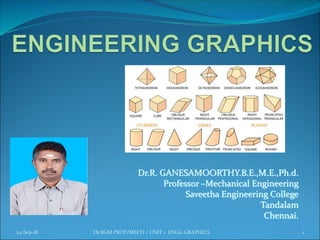
  • 29. Geometric Construction Conti........ Solids are obtained by combination of planes. Plane surfaces of simple solids are shown in figure. 24-Sep-18 Dr.RGM PROF/MECH / UNIT 1 ENGG GRAPHICS 29
  • 30. To divide a straight line into a given number of equal parts say 5. Construction 24-Sep-18 Dr.RGM PROF/MECH / UNIT 1 ENGG GRAPHICS 30 1. Draw AC at any angle θ to AB. 2. Construct the required number of equal parts of convenient length on AC like 1,2,3. 3. Join the last point 5 to B 4. Through 4, 3, 2, 1 draw lines parallel to 5B to intersect AB at 4',3',2' and 1'.
  • 31. 24-Sep-18 Dr.RGM PROF/MECH / UNIT 1 ENGG GRAPHICS 31 1. Draw a line AB and AC making the given angle. 2. With centre A and any convenient radius R draw an arc intersecting the sides at D and E. 3. With centers D and E and radius larger than half the chord length DE, draw arcs intersecting at F 4. Join AF, <BAF = <PAC. To bisect a given angle Construction
  • 32. To inscribe a square in a given circle Construction 1. With centre 0, draw a circle of diameter D. 2. Through the centre 0, draw two diameters, say AC and BD at right angle to each other. 3. Join A-B, B-C, C- D, and D-A. ABCD is the required square. 24-Sep-18 Dr.RGM PROF/MECH / UNIT 1 ENGG GRAPHICS 32
  • 33. To inscribe a hexagon in a given circle. By using a set-square or mini-draughter 1. With centre 0 and radius R draw the given circle. 2. Draw any diameter AD to the circle. 3. Using 30° - 60° set-square and through the point A draw lines AI, A2 at an angle 60° with AD, intersecting the circle at B and F respectively. 4. Using 30° - 60° and through the point D draw lines Dl, D2 at an angle 60° with DA, intersecting the circle at C and E respectively. By joining A, B, C, D, E, F, and A the required hexagon is obtained. 24-Sep-18 Dr.RGM PROF/MECH / UNIT 1 ENGG GRAPHICS 33
  • 34. To inscribe a hexagon in a given circle. By using compass 1. With centre 0 and radius R draw the given circle. 2. Draw any diameter AD to the circle. 3. With centres A and D and radius equal to the radius of the circle draw arcs intersecting the circles at B, F, C and E respectively. 4. ABC D E F is the required hexagon. 24-Sep-18 Dr.RGM PROF/MECH / UNIT 1 ENGG GRAPHICS 34
  • 35. To circumscribe a hexagon on a given circle of radius R construction 1. With centre 0 and radius R draw the given circle. 2. Using 60° position of the mini draughter or 300- 600set square, circumscribe the hexagon as shown. 24-Sep-18 Dr.RGM PROF/MECH / UNIT 1 ENGG GRAPHICS 35
  • 36. To construct a hexagon, given the length of the side (a)Using set square 1. Draw a line AB equal to the side of the hexagon. 2. Using 30° - 60° set-square draw lines AI, A2, and BI,B2. 3. Through 0, the point of intersection between the lines A2 at D and B2 at E. 4. Join D,E 5. ABC D E F is the required hexagon. 24-Sep-18 Dr.RGM PROF/MECH / UNIT 1 ENGG GRAPHICS 36
  • 37. To construct a hexagon, given the length of the side (b) By using compass 1. Draw a line AB equal to the of side of the hexagon. 2. with centres A and B and radius AB, draw arcs intersecting at 0, the centre of the hexagon. 3. With centres 0 and B and radius OB (=AB) draw arcs intersecting at C. 4. Obtain points D, E and F in a similar manner. 24-Sep-18 Dr.RGM PROF/MECH / UNIT 1 ENGG GRAPHICS 37
  • 38. To construct a regular polygon (say a pentagon) given the length of the side. 1. Draw a line AB equal to the side and extend to P such that AB = BP 2. Draw a semicircle on AP and divide it into 5 equal parts by trial and error. 3. Join B to second division 4. Irrespective of the number of sides of the polygon B is always joined to the second division. 5. Draw the perpendicular bisectors of AB and B2 to intersect at O. 6. Draw a circle with 0 as centre and OB as radius. 7. With AB as radius intersect the circle successively at D and E.Then join CD. DE and EA. 24-Sep-18 Dr.RGM PROF/MECH / UNIT 1 ENGG GRAPHICS 38
  • 39. To construct a regular polygon (say a hexagon) given the side AB – alternate Method. 1. Steps 1 to 3 are same as above 2. Join B- 3, B-4, B-5 and produce them. 3. With 2 as centre and radius AB intersect the line B, 3 produced at D. Similarly get the point E and F. 4. Join 2- D, D-E, E-F and F-A to get the required hexagon. 24-Sep-18 Dr.RGM PROF/MECH / UNIT 1 ENGG GRAPHICS 39
  • 40. To construct a pentagon, given the length of side. 1. Draw a line AB equal to the given length of side. 2. Bisect AB at P. 3. Draw a line BQ equal to AB in length and perpendicular to AB. 4. With centre P and radius PQ, draw an arc intersecting AB produced at R. AR is equal to the diagonal length of the pentagon. 5. With centres A and B and radii AR and AB respectively draw arcs intersecting at C. 6. With centres A and B and radius AR draw arcs intersecting at D. 7. With centres A and B and radii AB and AR respectively draw arcs intersecting at E. ABCDE is the required pentagon. 24-Sep-18 Dr.RGM PROF/MECH / UNIT 1 ENGG GRAPHICS 40
  • 41. By included angle method 1.Draw a line AB equal to the length of the given side. 2.Draw a line B 1 such that <AB 1 = 108° (included angle) 3.Mark C on B1 such that BC = AB 4.Repeat steps 2 and 3 and complete the pentagon ABCDE 24-Sep-18 Dr.RGM PROF/MECH / UNIT 1 ENGG GRAPHICS 41 To construct a pentagon, given the length of side.