Introduction to Scale drawings in Construction
•Download as DOC, PDF•
12 likes•26,227 views

Scales are used in construction drawings to reduce the size of buildings, land plots, and large components so they fit on paper. Common scales include 1:1 for templates, 1:10 for details, 1:50 for plans/elevations/sections, and 1:500 for site plans. Hatching is used to indicate materials, with lines representing brick, dots for concrete. Abbreviations and symbols are used to efficiently provide information on drawings. Working drawings contain elevations showing external finishes and openings, plans with room layouts and fittings, sections with construction details, and a site plan locating the building on the land.

Recommended
More Related Content
What's hot
What's hot (20)
Viewers also liked
Viewers also liked (19)
Similar to Introduction to Scale drawings in Construction
Similar to Introduction to Scale drawings in Construction (20)
More from Steve Jarvis
More from Steve Jarvis (16)
Recently uploaded
Recently uploaded (20)
Introduction to Scale drawings in Construction
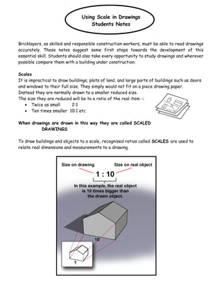
- 1. Using Scale in Drawings Students Notes Bricklayers, as skilled and responsible construction workers, must be able to read drawings accurately. These notes suggest some first steps towards the development of this essential skill. Students should also take every opportunity to study drawings and wherever possible compare them with a building under construction. Scales It is impractical to draw buildings, plots of land, and large parts of buildings such as doors and windows to their full size. They simply would not fit on a piece drawing paper. Instead they are normally drawn to a smaller reduced size. The size they are reduced will be to a ratio of the real item -: • Twice as small 2:1 • Ten times smaller 10:1 etc When drawings are drawn in this way they are called SCALED DRAWINGS To draw buildings and objects to a scale, recognised ratios called SCALES are used to relate real dimensions and measurements to a drawing. 1
- 2. The main scales or ratios used in construction drawings are-: 1:1 Full size used for unusual details or templates 1:2 1:5 Complicated building details 1:10 1:20 1:50 Plans, elevations and sections 1:100 1:200 1:200 1:500 Site plans 1:1250 1:1250 Block or location plans 1:2500 Task 1 Complete the table below, filling in the missing scales 2 Scale Drawing is: Scale Drawing is: 1:1 The same size as the object 1:100 100 times smaller than the object 1:5 5 times smaller than the object 1:200 1:10 1:500 500 times smaller than the object 1:20 20 times smaller than the object 1:1250 1250 times smaller than the object 1:50
- 3. Task 2 (If the number used in the scale is multiplied by the measurements used to draw the plan, the actual measurements can be found ) Look these drawings of two walls. A scale of 1:50 has been used for Wall A whereas a scale of 1:100 has been used for Wall B. They both look the same on paper but in real life they would be very different sizes! What is the height in real life? 25mm × 50 = 1250mm Divide by 1000 to convert mm to m = 1.25m What is the height in real life? _____ mm The bigger wall in real life is Wall _____ Try this Write in the scale that would make Wall C 5 times bigger than Wall B in real life. 3 80m on site 120m on site 1 on drawing = 2500 on site SCALE RULE
- 4. Hatching Hatching is a term given to the markings on a cross sectional drawing used to indicate the material that it is constructed of. They are official British Standards and can be found in BS: 1192 which controls drawing practice across all sections of the Construction Industry Task 3 From the powerpoint slide complete the missing hatching titles. 4
- 5. Abbreviations Abbreviations are a simple way of conveying information on drawings, reducing words to first letters, e.g. rain water pipe becomes R.W.P. They allow the maximum information to be included on the drawing in a concise way. Abbreviations have to be used in context e.g. MS stands for Mild Steel in the context of construction but it could also be an abbreviation for some other word in another situation. Avoid making up your own abbreviations as these can lead to confusion. Abbreviations Aggregate agg Air brick Ab Graphical Sybols Aluminium al Asbestos asb Asphalt asph Bitumen bit Boarding bdg Brickwork bwk BS Beam BSB Building bldg Cast iron CI Cement ct Column col Concrete conc Copper cu Damp proof course dpc Discharge pipe DP Foundation fdn Hardcore hc Hardboard hdbd Hardwood hwd Inspection chamber IC Insulation insul Tongued and grooved t&g Joist jst Plasterboard pbd 5
- 6. Reinforced conc RC Graphical Symbols These are small standard pictures used to reduce the amount of drawing detail required on individual drawings. Abbreviations and graphical symbols are often used together to give complete information. Representation of components - fittings Sink Bath Bidet Toilet Hot & Cold Cold water Hot Water Stop Valve Water drain off Cistern Cylinder Radiator Towel rail Boiler Cooker Pump Drain or Sewer Flow Foul water Rainwater head 6
- 7. Surface water Rainwater outlet Gulley Task 4 Complete the following section through the foundation of a building up to window level with the correct hatchings. 7
- 8. Working Drawings A working drawing and written specification should contain the total information required For a building team to convert the architects proposed building into a completed structure. To enable this to happen the following information should be found in the following locations. ELEVATIONS: 1. External finish to walls and roof 2. Position of window and door openings Scale used 1:200, 1:100, 1:50 PLANS: 1. Overall dimensions of the building 2. Position of internal walls, room sizes door and window openings 3. Position of fitments, baths, sinks toilets, stairs etc Scale used 1:200, 1:100, 1:50 8
- 9. SECTIONS: 1. Provide vertical dimensions 2. Provide constructional details of foundations, floors, walls, roof, damp proof membranes and ground levels SITE PLAN: 1. Position of the building in relation to the site surroundings i.e. adjoining buildings, roads, boundaries, etc. 2. Provision of access 3. Drains and main sewer 4. North point 9
- 10. BLOCK PLAN: 1. Location of site in relation to surrounding district. This is taken from local authority’s ordance survey map. COMPONENT DRAWINGS: 1. These show the basic sizes of standard components such as doors, windows and kitchen fitments. scales most commonly used are 1:100, 1: 50, 1: 20. LEGAL or TITLE PANEL: 10
- 11. 1. Site Address 2. Scales used on drawing 3. Drawing Number 4. Client 5. Date of drawing DETAIL DRAWING: These drawings will include every detail required to make the product. The information from these details is used to manufacture various components . These drawings are usually produced by the architect and are produced in scales ranging from 1:1, 1;5, or 1:10. 11
- 12. ASSEMBLY DRAWING: These drawings are very important to the builder. They show in detail how the architect requires the construction to be constructed and what materials should be used . The scales usually used for these drawings are 1:20, 1:10, 1:5 and should be fully dimensioned and annotated. 12 Key Points • Select drawing required consulting Index if available • Ensure it is the latest amended version • First, get an overall picture before looking at details. • Check the sum of intermediate dimensions equals the overall dimension • Do not scale from drawings • Take every opportunity to compare drawings with the current construction