Download as PDF, PPTX

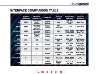


This document provides a summary and comparison of various storage interface types, including their maximum transfer rates, attributes, cable types, and distances supported. It also includes tables comparing the interfaces and notes that the document will be periodically updated with additional information. Demartek analyzes storage, server, and networking technologies through hands-on testing and research.


