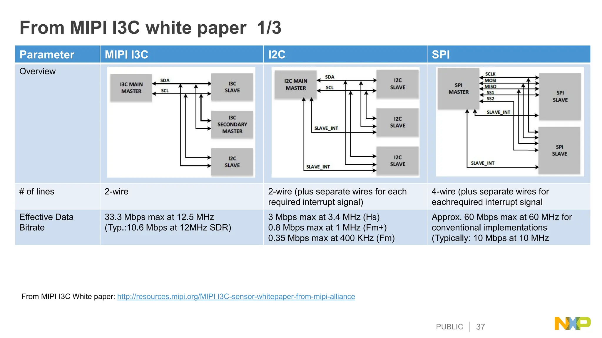
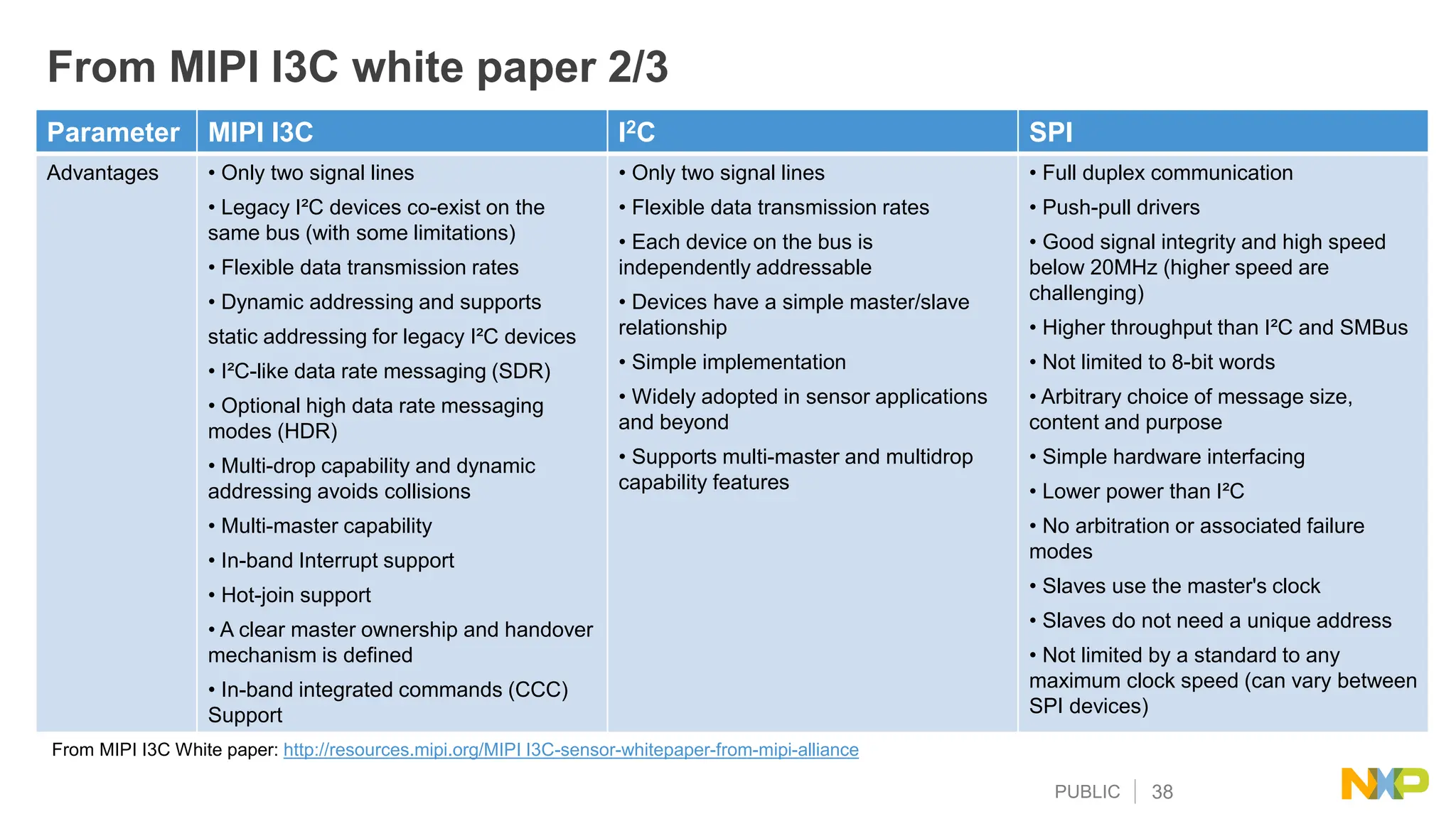
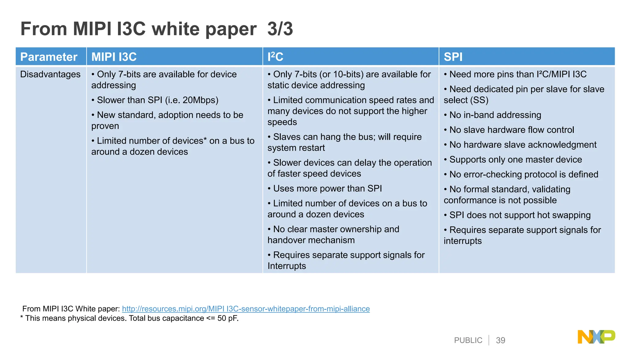
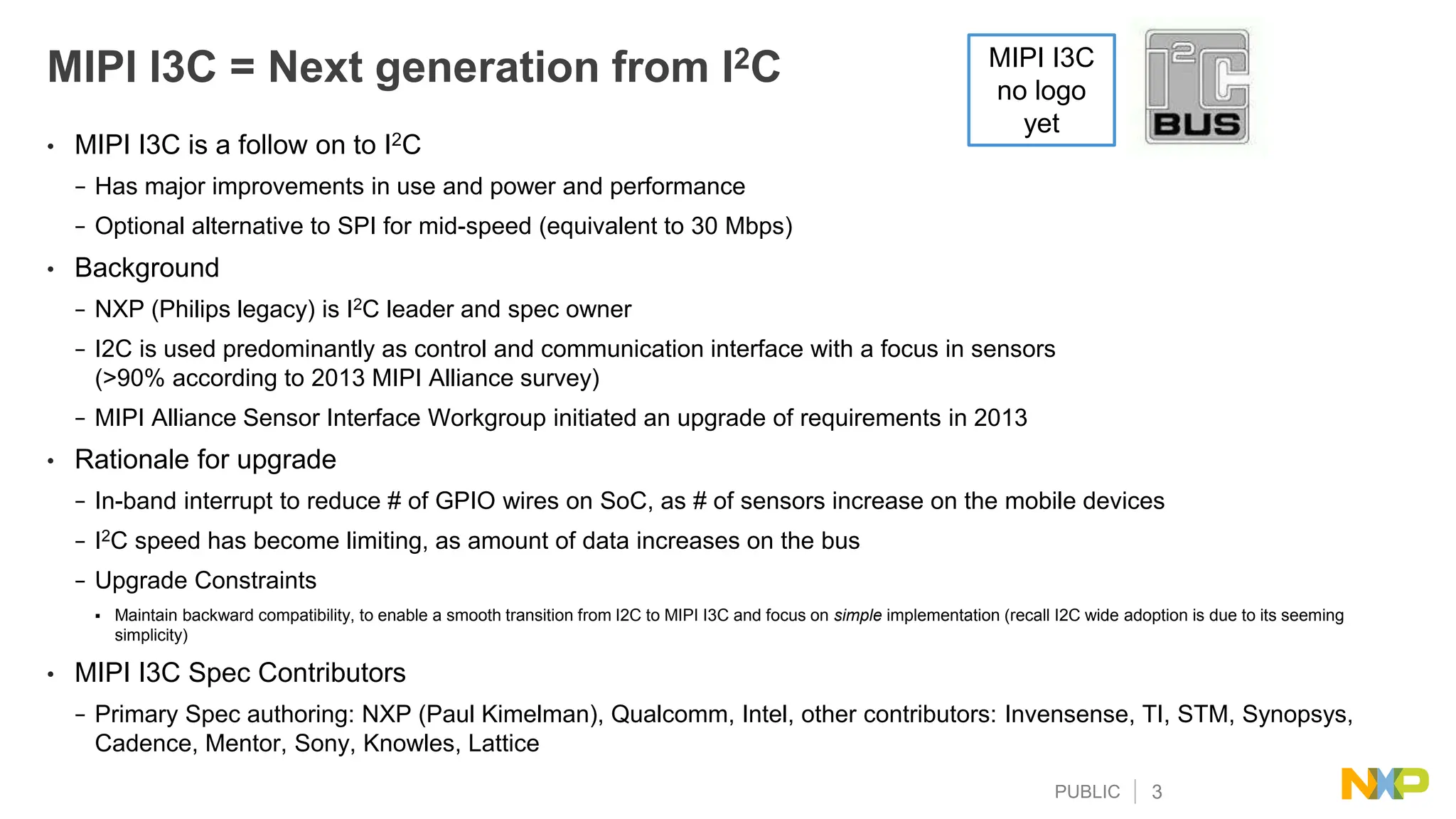
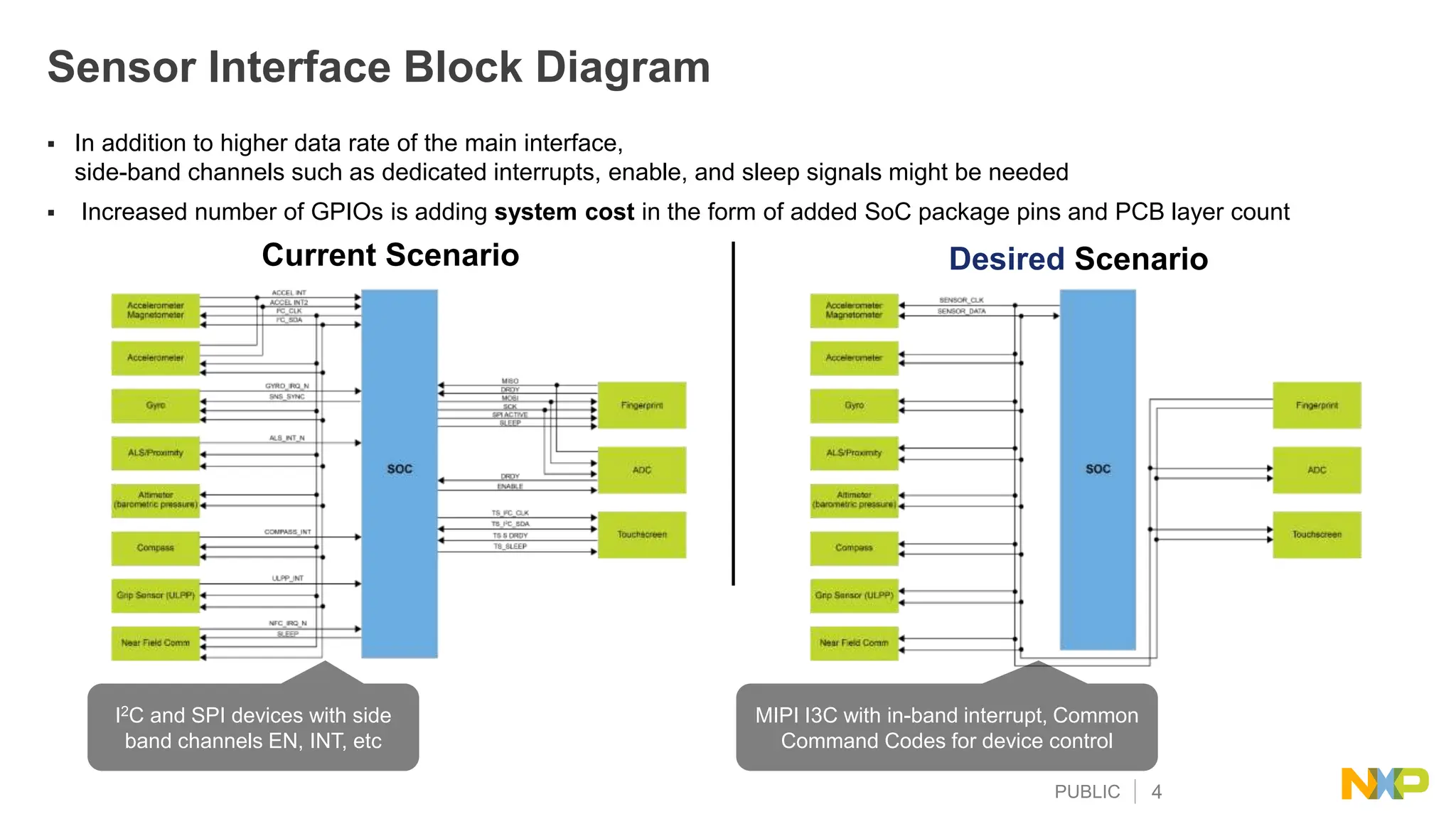
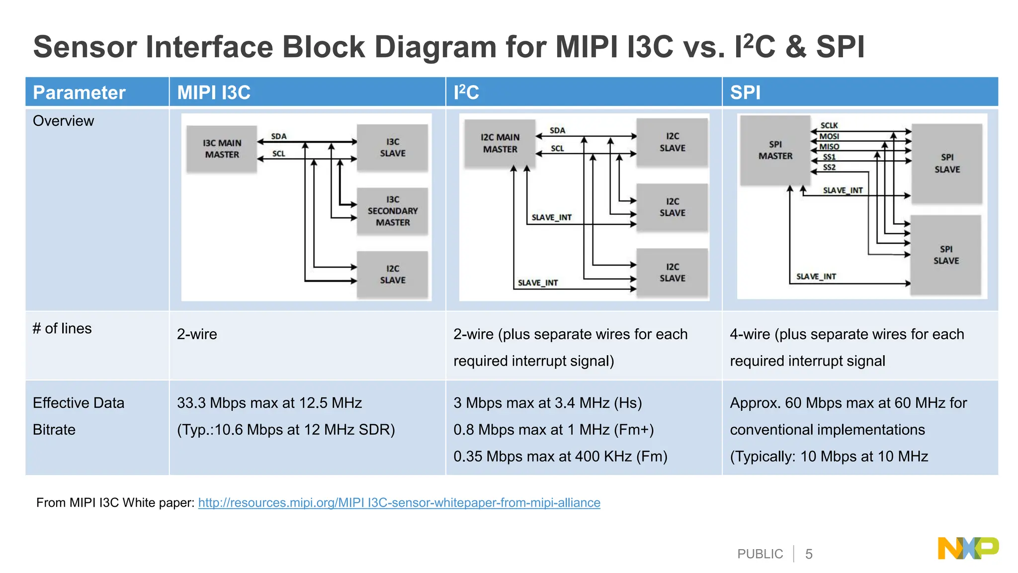
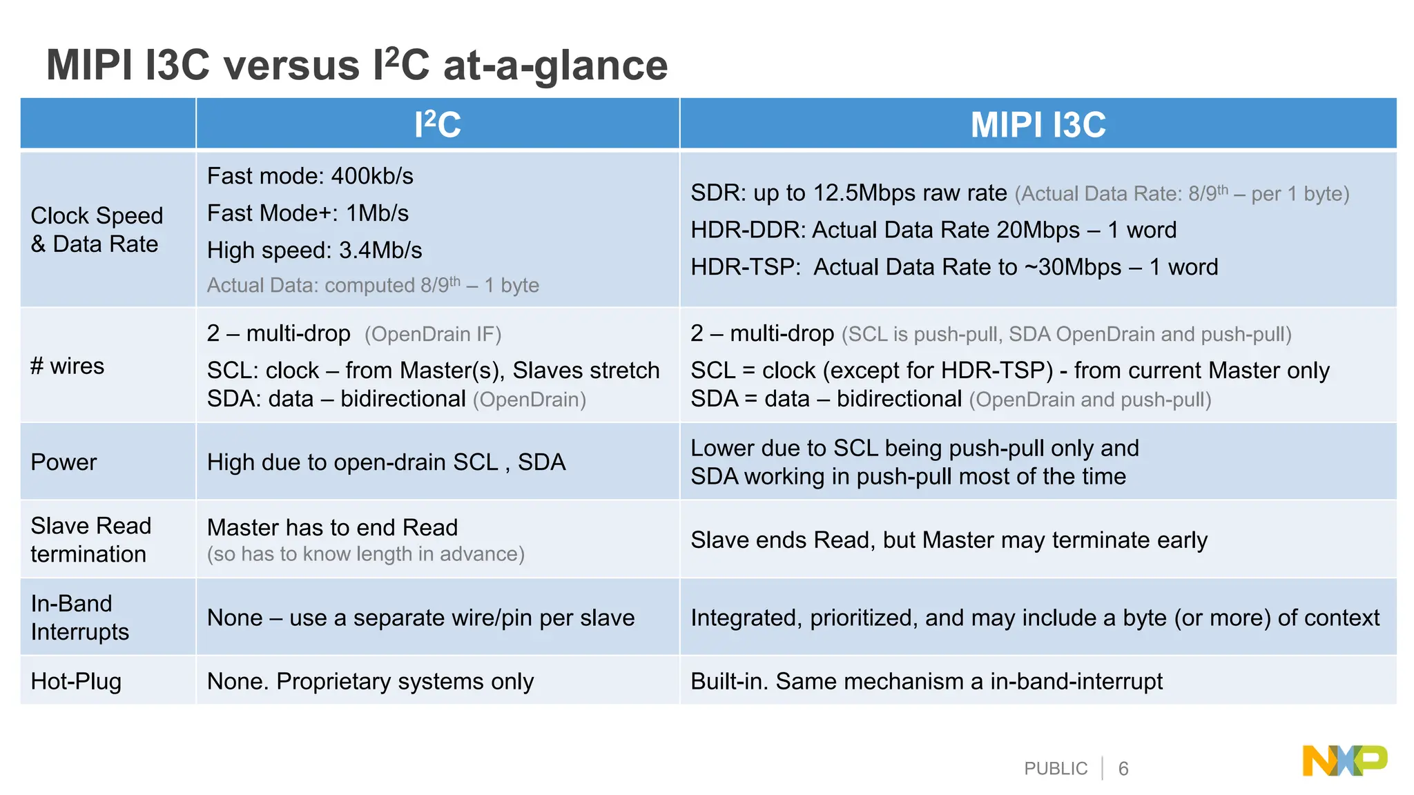
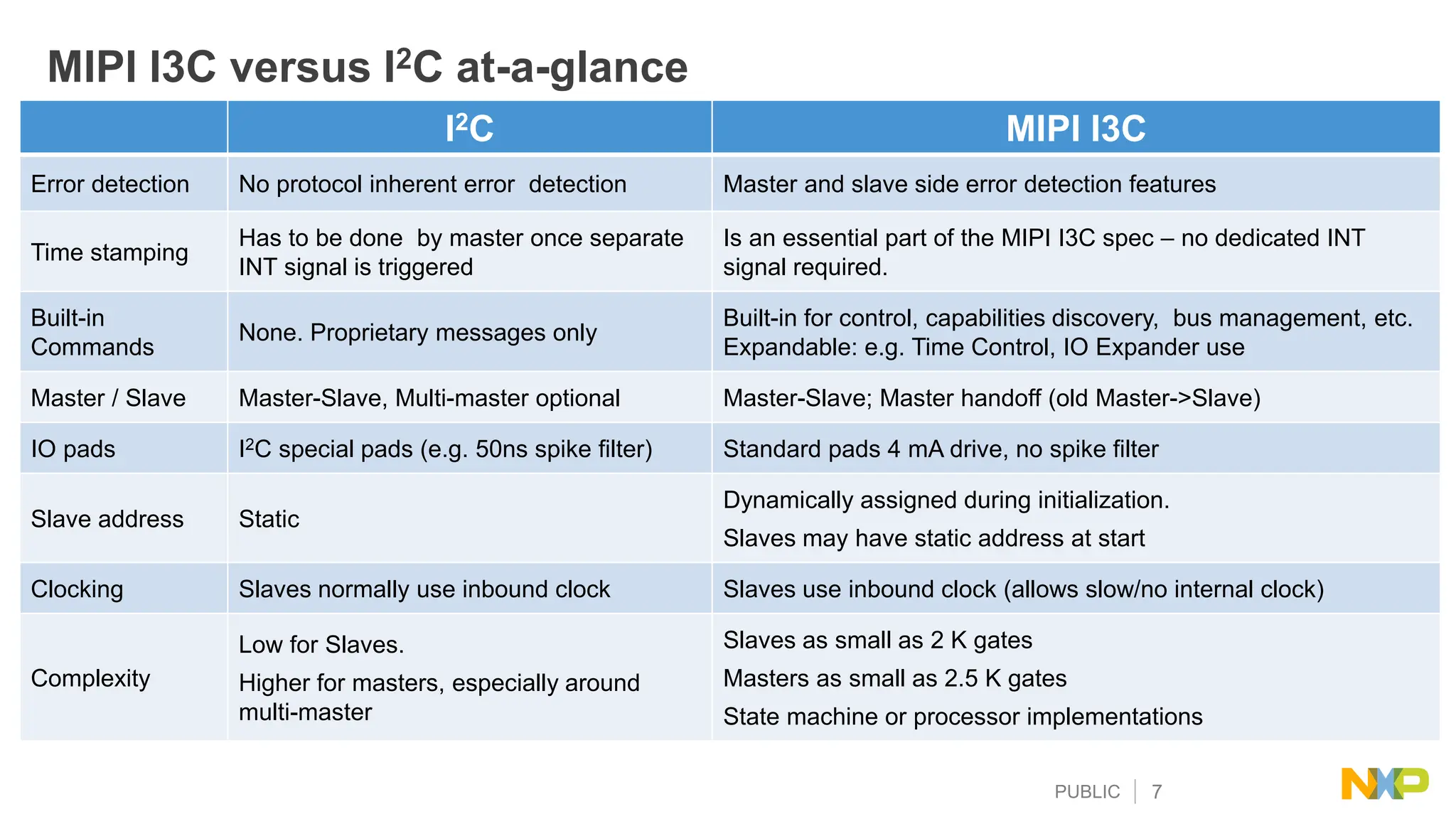
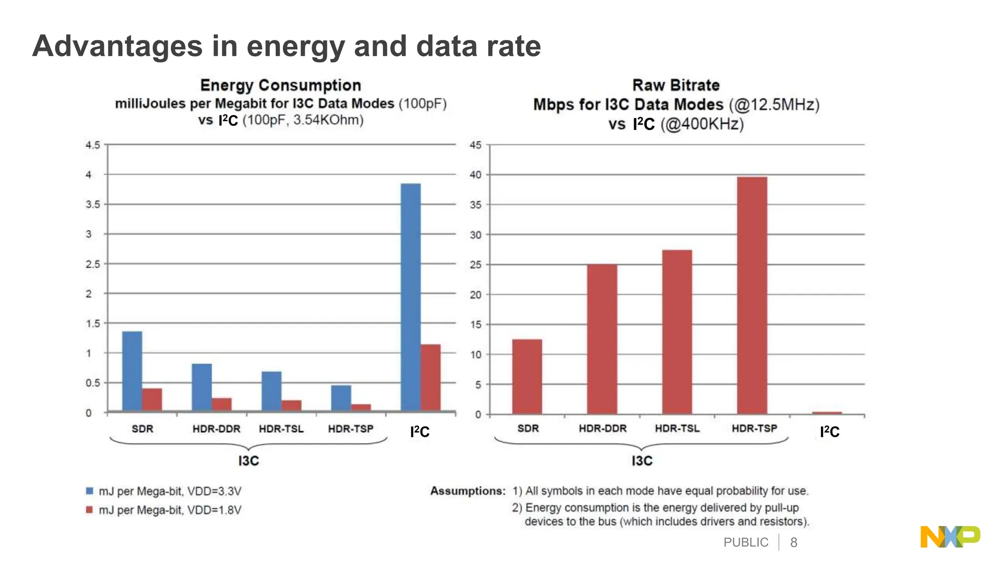
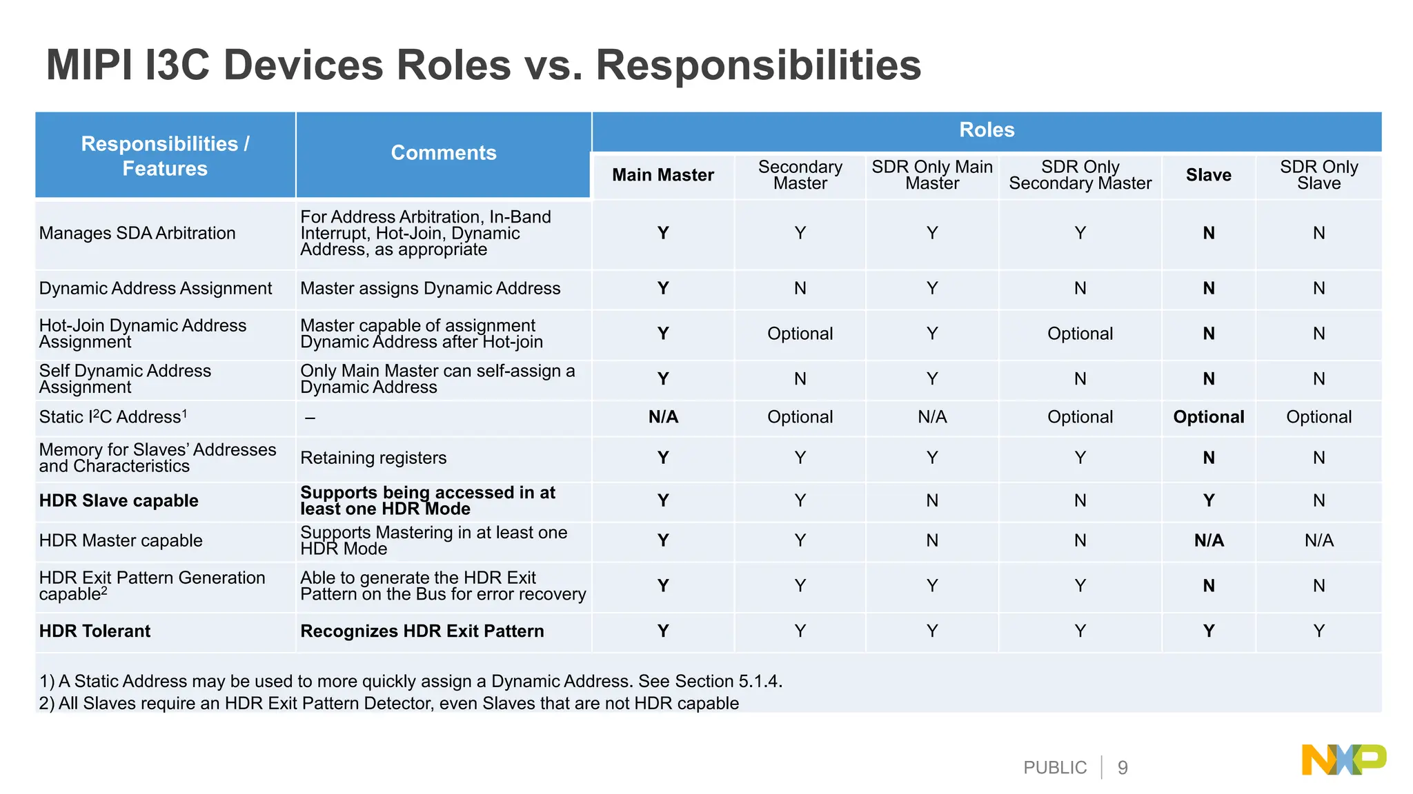
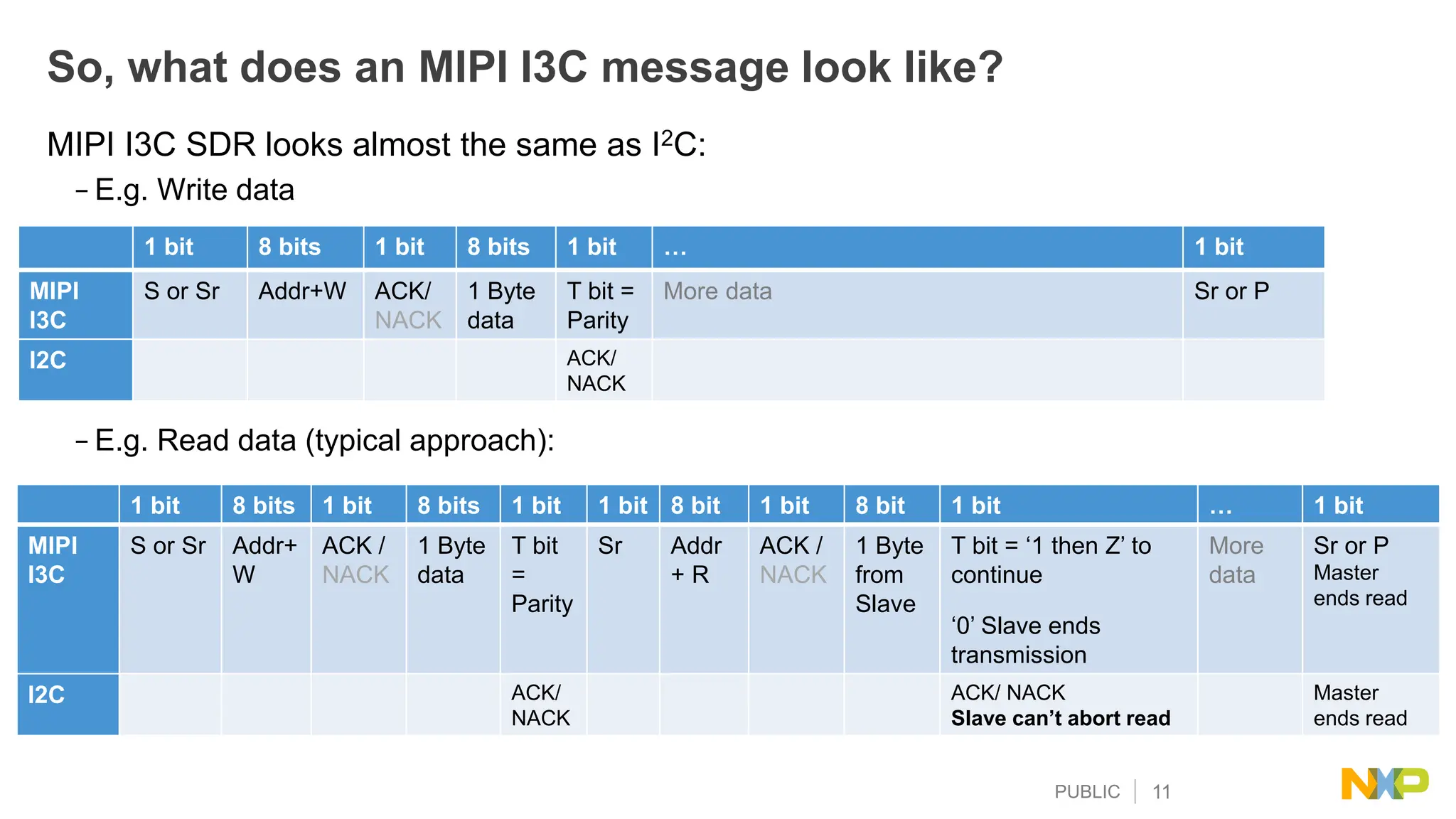
The document provides an overview of the MIPI I3C technology, which is a successor to I2C, emphasizing its improvements in data rate, energy efficiency, and support for additional features like in-band interrupts. It contrasts MIPI I3C's capabilities against I2C and SPI in terms of signaling, protocol, and bus architecture. Key topics include data rates, error detection, device identification, and the roles of masters and slaves within the MIPI I3C framework.


![PUBLIC 19
10. [A2:A0] are latched by master (‘111’)
address 7’ 5F successfully transmitted
by slave to master
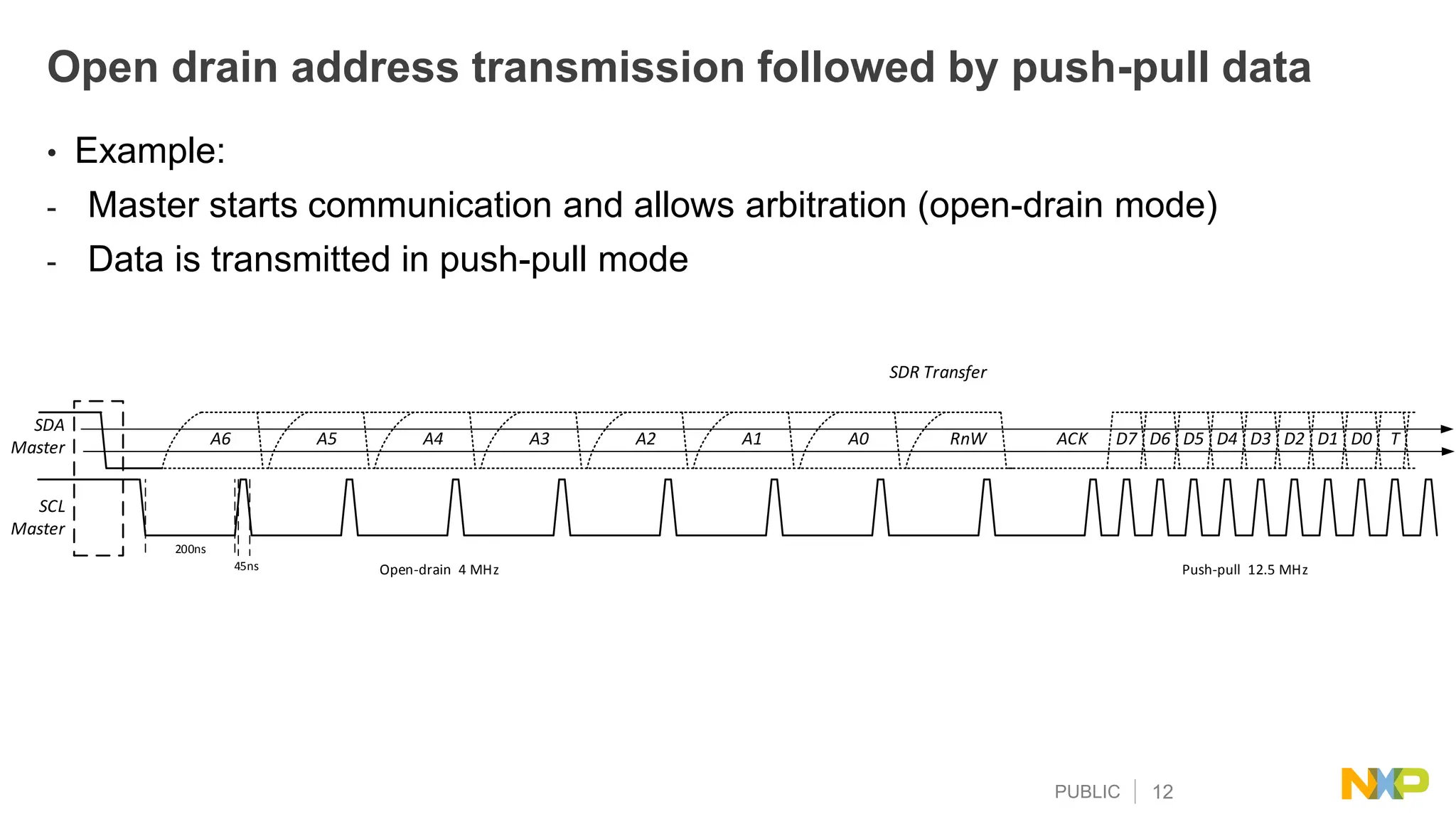
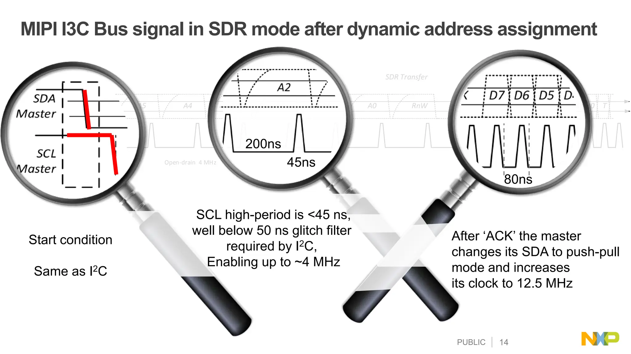
11. Master changes over to push-pull operation
SDA
Master
SCL
Master
SDR Transfer
A6 A5 A4 A3 A2 A1 A0 RnW ACK D7 D6 D5 D4 D3 D2 D1 D0 T
200ns
45ns Open-drain 4 MHz Push-pull 12.5 MHz
SDA
Slave
7'77
A6 A5 A4 A3 A2 A1 A0 RnW ACK D7 D6 D5 D4 D3 D2 D1 D0 T
SDA
Slave
7'5F
A6 A5 A4 A3 A2 A1 A0 RnW ACK D7 D6 D5 D4 D3 D2 D1 D0 T
SDA
Master
SCL
Master
SDR Transfer
A6 A5 A4 A3 A2 A1 A0 RnW ACK D7 D6 D5 D4 D3 D2 D1 D0 T
200ns
45ns Open-drain 4 MHz Push-pull 12.5 MHz
SDA
Slave
7'77
A6 A5 A4 A3 A2 A1 A0 RnW ACK D7 D6 D5 D4 D3 D2 D1 D0 T
SDA
Slave
7'5F
A6 A5 A4 A3 A2 A1 A0 RnW ACK D7 D6 D5 D4 D3 D2 D1 D0 T
8
2
1 3, 4,5,6 7 9
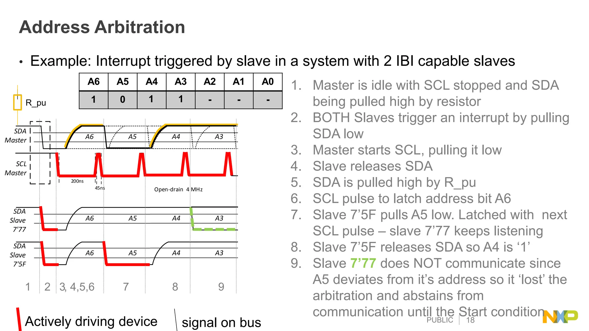
Address Arbitration
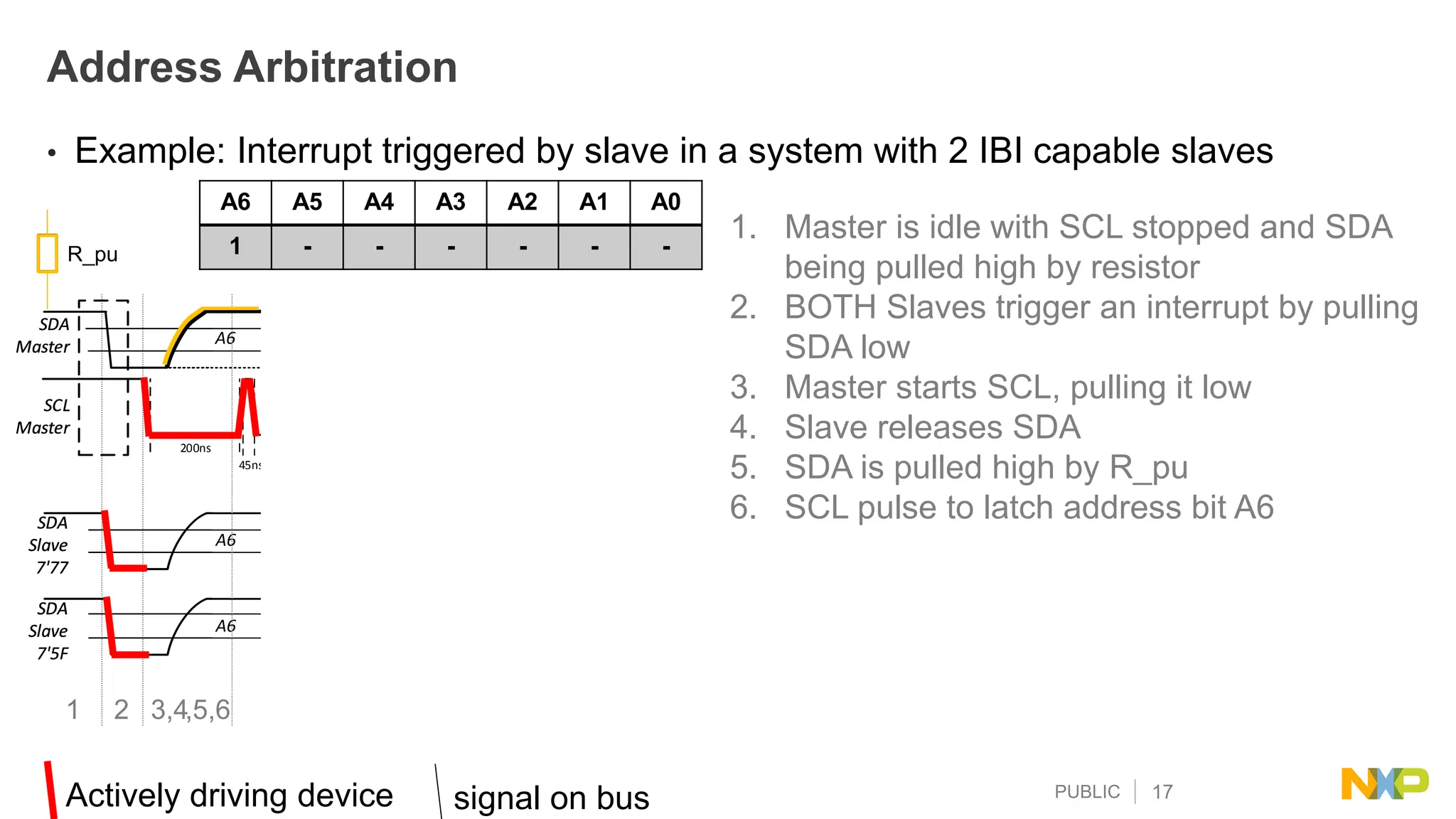
• Example: Interrupt triggered by slave in a system with 2 IBI capable slaves
R_pu
Actively driving device signal on bus
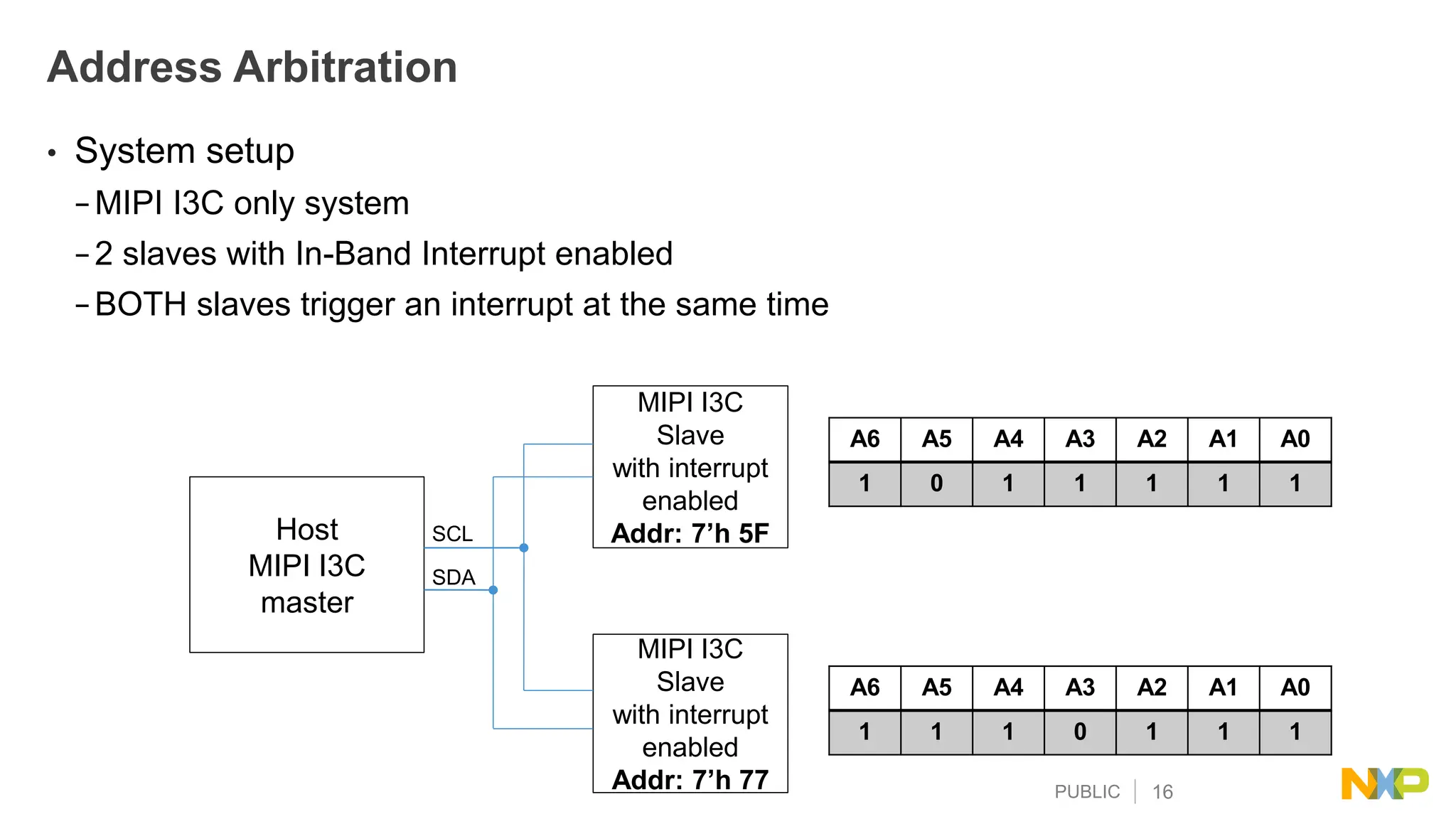
A6 A5 A4 A3 A2 A1 A0
1 0 - - - - -
1 1 1 1 1
10 11](https://image.slidesharecdn.com/amf-des-t26861-240226095228-5634f0b3/75/This-Document-gives-a-complete-understanding-of-the-I3C-protocol-which-is-introduced-by-the-MIPI-Alliance-pdf-20-2048.jpg)


![PUBLIC 28
Device Identifier - MIPI I3C slave addresses
Device Identifier
In order to support the Dynamic Address Assignment procedure, each MIPI I3C Device to be connected to an
MIPI I3C Bus shall be uniquely identifiable in one of two ways, before starting the procedure.
1. The Device may have a Static Address, in which case the Master may use that Static Address
For example, an Address similar to what I2C specifies
2. The Device shall in all cases have a 48-bit Provisional ID.
The Master shall rely on this 48-bit Provisional ID, unless the Device has a Static Address used by the master.
The 48-bit Provisional ID is composed of three parts:
Bits [47:33] Bit [32] Bits [31:00]
[31:16]
16 bits
[15:12]
4 bits
[11:0]
12 bit
MIPI
Manufacturer ID
(Note: MSB is
discarded)
Provisional ID Type
Selector
1’b1: Random
1’b0: Fixed
Part ID: The meaning
of this 16-bit field is
left to the Device
vendor to define
Instance ID: Value to identify the
individual example: straps,
fuses, non-volatile memory, or
another appropriate method
This is left for definition with additional
meaning. For example: deeper Device
Characteristics, which could optionally
include Device Characteristic Register
values
If Bit [32] = 1’b1: Random Value:
Bits [31:0]: 32-bit value randomly generated by the Device.](https://image.slidesharecdn.com/amf-des-t26861-240226095228-5634f0b3/75/This-Document-gives-a-complete-understanding-of-the-I3C-protocol-which-is-introduced-by-the-MIPI-Alliance-pdf-29-2048.jpg)