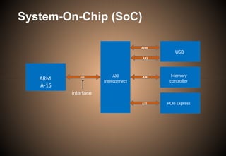
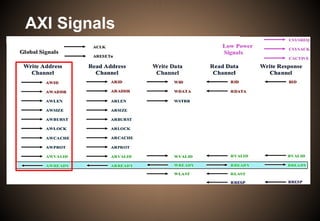
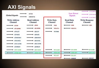
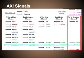
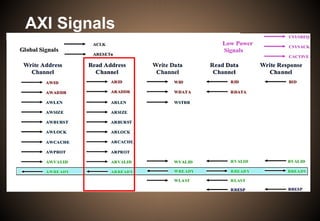
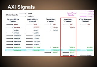
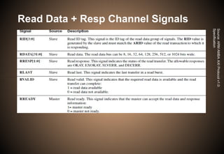
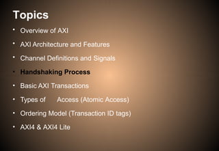
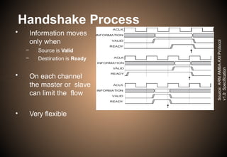
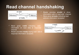
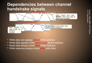
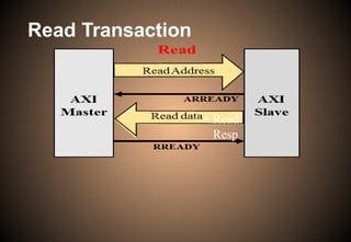
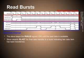
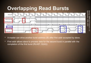
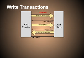
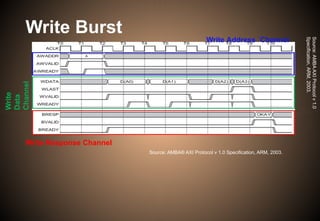
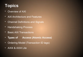
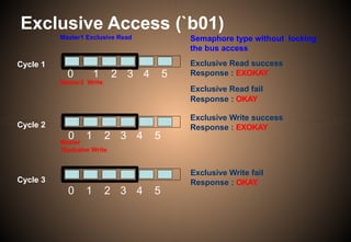
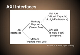
The document provides an extensive overview of the ARM AMBA AXI protocol, detailing its architecture, channel definitions, handshaking processes, transactions, and features like atomic access and ordering models. It describes how the AXI interface facilitates on-chip communication between multiple masters and slaves, and outlines the types of access, burst transfers, and signal handling during transactions. Additionally, the document explains the intricacies of transaction management, including out-of-order transactions and cache support features.


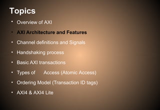


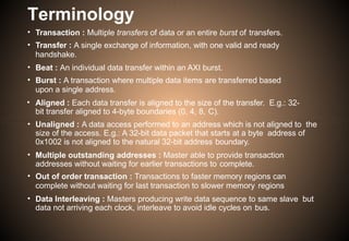


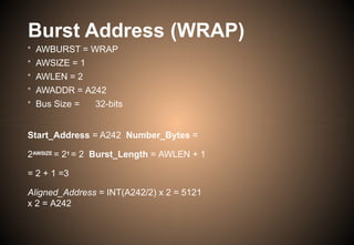
![Burst Operation[5]
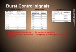
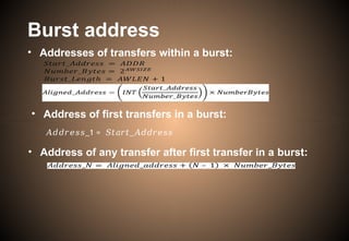
Burst length
1 beat
2 beats
16 beats
Undefined
length
4 beats
8 beats
SIZE
Word
halfword
…
…
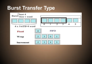
Burst
Transfer
………
………](https://image.slidesharecdn.com/axiprotocol-241017111337-62a89385/85/AXI-Protocol-amba-axi-architecture-protocol-42-320.jpg)

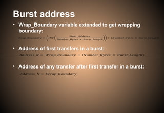


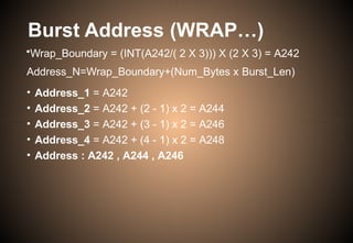

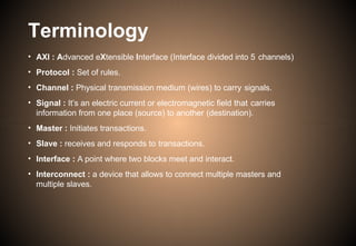
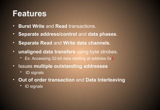
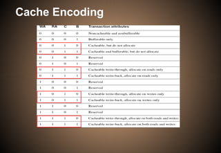
![• Support for system level caches and other
performance enhancing components
• Bufferable (B) bit, ARCACHE[0] and AWCACHE[0]
• Cacheable (C) bit, ARCACHE[1] and AWCACHE[1]
• Read Allocate (RA) bit, ARCACHE[2] and AWCACHE[2]
• Write Allocate (WA) bit, ARCACHE[3] and AWCACHE[3]
Cache Support](https://image.slidesharecdn.com/axiprotocol-241017111337-62a89385/85/AXI-Protocol-amba-axi-architecture-protocol-59-320.jpg)
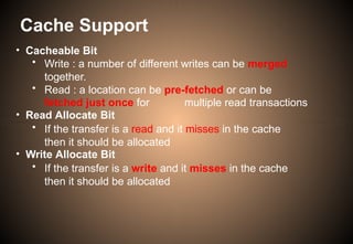
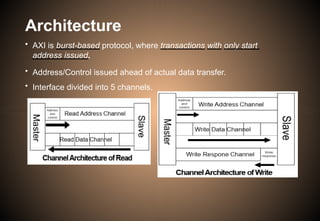
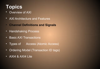
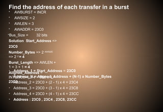
![• To support complex system design, for the interconnect and
other devices in the system to provide protection against
illegal transactions
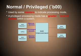
• Normal or privileged, ARPROT[0] andAWPROT[0]
• Low High
• Secure or non-secure, ARPROT[1] andAWPROT[1]
• Low High
• Data or instruction, ARPROT[2] andAWPROT[2]
• Low High
Protection Unit Support](https://image.slidesharecdn.com/axiprotocol-241017111337-62a89385/85/AXI-Protocol-amba-axi-architecture-protocol-63-320.jpg)


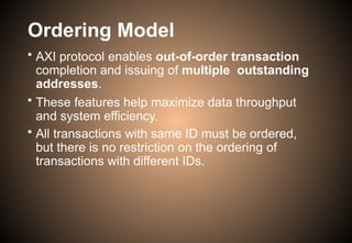
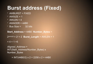
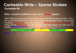
![Ordering Model [1]
• Multiple Outstanding Address
• Master is able to provide transaction addresses without waiting for
earlier transactions to complete.
• Write data Interleaving
• If two masters generate write data sequence to the same slave, but
write data doesn't arrive every clock cycle.
• Instead of waiting for a data sequence to complete before other
sequence starts, AXI system can interleave write data sequences
avoiding idle cycles on the bus.
[1] AMBA AXI Protocol v 1.0 Specification, ARM, 2003.](https://image.slidesharecdn.com/axiprotocol-241017111337-62a89385/85/AXI-Protocol-amba-axi-architecture-protocol-74-320.jpg)
![Read Data Interleaving[5]](https://image.slidesharecdn.com/axiprotocol-241017111337-62a89385/85/AXI-Protocol-amba-axi-architecture-protocol-76-320.jpg)
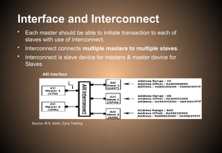
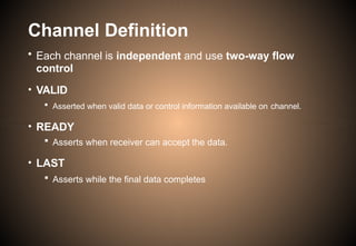
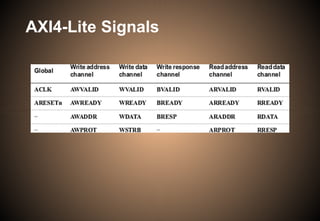
![Write Data Interleaving[5]
• Write data interleaving enables a slave interface
to accept interleaved write data with different
AWID values.
Figure: Write data Interleaving](https://image.slidesharecdn.com/axiprotocol-241017111337-62a89385/85/AXI-Protocol-amba-axi-architecture-protocol-78-320.jpg)


![References
[1]
[2]
[3]
[4]
[5]
AMBA AXI Protocol v 1.0 Specification, ARM, 2003.
AMBA Specification, Rev 2.0, ARM, 1999.
AMBA 4 AXI4-Stream Protocol Version 1.0
http://infocenter.arm.com/help/topic/com.arm.doc.set.amba https://
www.slideshare.net/AzadMishra1/axi-protocol-55779579](https://image.slidesharecdn.com/axiprotocol-241017111337-62a89385/85/AXI-Protocol-amba-axi-architecture-protocol-93-320.jpg)