2 UNIT-III
Direct-AttachedStorage, SCSI, and Storage Area Networks: Types of DAS, DAS Benefits
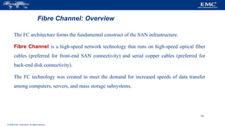
and Limitations, Disk Drive Interfaces, Introduction to Parallel SCSI, Overview of Fibre
Channel, The SAN and Its Evolution, Components of SAN, FC Connectivity, Fibre
Channel Ports, Fibre Channel Architecture, Zoning, Fibre Channel Login Types, FC
Topologies
3.
3 Direct-Attached Storage
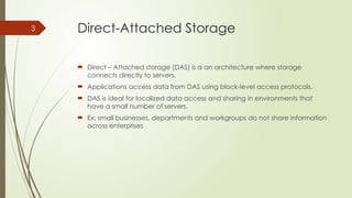
Direct – Attached storage (DAS) is a an architecture where storage
connects directly to servers.
Applications access data from DAS using block-level access protocols.
DAS is ideal for localized data access and sharing in environments that
have a small number of servers.
Ex: small businesses, departments and workgroups do not share information
across enterprises
4.
4 What isDAS?
Uses block level protocol for data access
Internal Direct Connect External Direct Connect
DAS w/ internalcontroller and
external storage
CPU
Memory
Bus
I/O - RAID
Controller
Computer System
Disk Drives
Disk Drives
Disk Drives
Disk Enclosure
12345
John
Sm
ith
512-555-1212
1424 Main Street
9.
Comparing Internal andExternal Storage
Internal Storage
Server
Storage
RAID controllers
and disk drives are
internal to the
server
SCSI, ATA, or SATA
protocol between
controller and disks
SCSI Bus w/ external storage
Server
RAID Controller
Storage
RAID Controller
Disk Drives
RAID controller is
internal
SCSI or SATA
protocol between
controller and disks
Disk drives are
external
Disk Drives
10.
DAS w/ externalcontroller and
external storage
Computer System
CPU
Memory
Bus
HBA
RAID
Controller
Storage System
Disk Drives
Disk Drives
Disk Drives
Disk Enclosure
12345
John
Sm
ith
512-555-1212
1424 Main Street
11.
DAS over FibreChannel
Server
HBA
Storage
Disk drives and
RAID controller
are external
Disk Drives
RAID Controller
HBA is internal
Fibre Channel
protocol
between HBAs
and external
RAID controller
External SAN Array
12.
I/O Transfer
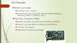
RAID Controller
Containsthe “smarts”
Determines how the data will be written (striping,
mirroring, RAID 10, RAID 5, etc.)
Host Bus Adapter (HBA)
Simply transfers the data to the RAID controller.
Doesn’t do any RAID or striping calculations.
“Dumb” for speed.
Required for external storage.
NAS: What isit?
Network Attached Storage
Utilizes a TCP/IP network to “share” data
Uses file sharing protocols like Unix NFS and Windows CIFS
Storage “Appliances” utilize a stripped-down OS that optimizes file
protocol performance
15.
Networked Attached Storage
NASServer
Storage
Server has a
Network
Interface Card
No RAID
Controller or
HBA in the server
Public or Private Ethernet
network
RAID Controller
Disk Drives
All data
converted to file
protocol for
transmission (may
slow down
database
transactions)
Server
NIC NIC
16.
iSCSI: What isit?
An alternate form of networked storage
Like NAS, also utilizes a TCP/IP network
Encapsulates native SCSI commands in TCP/IP packets
Supported in Windows 2003 Server and Linux
TCP/IP Offload Engines (TOEs) on NICs speed up packet encapsulation
17.
iSCSI Storage
iSCSI Storage
Serverhas a
Network
Interface Card
or iSCSI HBA
iSCSI HBAs use
TCP/IP Offload
Engine (TOE)
Public or Private Ethernet
network
RAID Controller
Disk Drives
SCSI commands
are
encapsulated in
TCP/IP packets
Server
NIC or iSCSI HBA NIC or iSCSI HBA
18.
18 DAS Benefits
Ideal for local data provisioning
Quick deployment for small environments
Simple to deploy
Low capital expense
Low complexity
DAS needs lower initial investment than storage networking.
Setup is managed using host-based tools like host OS.
It requires fewer management tasks and less hardware and software elements to set up
and operate.
19.
19 DAS Challenges
Scalability is limited
Number of connectivity ports to hosts
Difficulty to add more capacity
Limited bandwidth
Distance limitations
Downtime required for maintenance with internal DAS
Limited ability to share resources
Array front-end port
Unused resources cannot be easily re-allocated
Resulting in islands of over and under utilized storage pools
20.
20 DAS ConnectivityOptions
ATA (IDE) and SATA
Primarily for internal bus
SCSI
Parallel (primarily for internal bus)
Serial (external bus)
FC
High speed network technology
Buss and Tag
Primarily for external mainframe
Precursor to ESCON and FICON
21.
21 Types ofDAS
There are two types of DAS depending on the location of the storage
device with respect to the host.
Internal DAS
External DAS
22.
22
DAS Management
Internal
Host provides:
Disk partitioning (Volume management)
File system layout
Direct Attached Storage managed individually through the server and the OS
External
Array based management
Lower TCO (Total Cost of Ownership) for managing data and storage
Infrastructure
23.
23 Internal DAS
In the internal DAS architecture, the storage device is internally connected
to the host by a serial or parallel bus.
The physical bus has distance limitations and can only be sustained over a
shorter distance for high-speed connectivity.
Most internal buses can support only a limited number of devices
They occupy a large amount of space inside the host, making
maintenance of other components difficult
24.
24 External DAS
In the external DAS architecture, the
server connects directly to the external
storage device.
Communication between the host and
the storage device takes place over SCSI
(Simple Computer System Interconnect)
or FC (Fiber Channel) protocol.
25.
25 DAS Limitations
A storage device has a limited number of ports.
A limited bandwidth in DAS restricts the available I/O processing capability.
The distance limitations associated with implementing DAS because of direct
connectivity requirements can be addressed by using Fibre Channel connectivity.
Unused resources cannot be easily re-allocated, resulting in islands of over-utilized and
under-utilized storage pools.
It is not scalable.
Disk utilization, throughput, and cache memory of a storage device, along with virtual
memory of a host govern the performance of DAS.
RAID-level configurations, storage controller protocols, and the efficiency of the bus
are additional factors that affect the performance of DAS.
The absence of storage interconnects and network latency provide DAS with the
potential to outperform other storage networking configurations.
26.
26 Disk DriveInterfaces
The host and the storage device in DAS communicate with each other by
using predefined protocols such as IDE/ATA, SATA, SAS, SCSI, and FC.
These protocols are implemented on the HDD controller. Therefore, a
storage device is also known by the name of the protocol it supports.
27.
27 IDE/ATA
AnIntegrated Device Electronics/Advanced Technology Attachment (IDE/ATA)
disk supports the IDE protocol.
The IDE component in IDE/ATA provides the specification for the controllers
connected to the computer’s motherboard for communicating with the device
attached.
The ATA component is the interface for connecting storage devices, such as CD-
ROMs, floppy disk drives, and HDDs, to the motherboard.
IDE/ATA has a variety of standards and names, such as ATA, ATA/ATAPI, EIDE, ATA-
2, Fast ATA, ATA-3, Ultra ATA, and Ultra DMA.
The latest version of ATA—Ultra DMA/133—supports a throughput of 133 MB per
second.
28.
28
IDE/ATA
In amaster-slave configuration, an ATA
interface supports two storage devices
per connector. However, if the
performance of the drive is important,
sharing a port between two devices is
not recommended.
A 40-pin connector is used to connect
ATA disks to the motherboard, and a 34-
pin connector is used to connect floppy
disk drives to the motherboard.
An IDE/ATA disk offers excellent
performance at low cost, making it a
popular and commonly used hard disk.
29.
29
SATA
A SATA(Serial ATA) is a serial version of the IDE/ATA specification.
SATA is a disk-interface technology that was developed by a group of the industry’s
leading vendors with the aim of replacing parallel ATA.
A SATA provides point-to-point connectivity up to a distance of one meter and
enables data transfer at a speed of 150 MB/s.
Enhancements to the SATA have increased the data transfer speed up to 600 MB/s.
A SATA bus directly connects each storage device to the host through a dedicated
link, making use of low-voltage differential signaling (LVDS
LVDS is an electrical signaling system that can provide high-speed connectivity over
low-cost, twisted-pair copper cables. For data transfer, a SATA bus uses LVDS with a
voltage of 250 mV.
30.
30 SATA
ASATA bus uses a small 7-pin connector and a thin cable for connectivity.
A SATA port uses 4 signal pins, which improves its pin efficiency compared to the parallel
ATA that uses 26 signal pins, for connecting an 80-conductor ribbon cable to a 40-pin
header connector.
SATA devices are hot-pluggable, which means that they can be connected or removed
while the host is up and running.
A SATA port permits single-device connectivity.
Connecting multiple SATA drives to a host requires multiple ports to be present on the
host.
Single-device connectivity enforced in SATA, eliminates the performance problems
caused by cable or port sharing in IDE/ATA.
31.
31
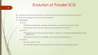
Evolution of ParallelSCSI
Developed by Shugart Associates & named as SASI (Shugart Associates System Interface)
ANSI acknowledged SCSI as an industry standard
SCSI versions
SCSI–1
Defined cable length, signaling characteristics, commands & transfer modes
Used 8-bit narrow bus with maximum data transfer rate of 5 MB/s
SCSI–2
Defined Common Command Set (CCS) to address non-standard implementation of the
original SCSI
Improved performance, reliability, and added additional features
SCSI–3
Latest version of SCSI
Comprised different but related standards, rather than one large document
32.
32 Evolution ofParallel SCSI
SCSI was developed to provide a device-independent mechanism for attaching to and
accessing host computers.
SCSI also provided an efficient peer-to-peer I/O bus that supported multiple devices.
SCSI is commonly used as a hard disk interface. However, SCSI can be used to add
devices, such as tape drives and optical media drives, to the host computer without
modifying the system hardware or software.
Over the years, SCSI has undergone radical changes and has evolved into a robust
industry standard.
33.
33
Evolution of ParallelSCSI
SCSI, first developed for hard disks, is often compared to IDE/ATA.
SCSI offers improved performance and expandability and compatibility options, making it
suitable for high-end computers.
However, the high cost associated with SCSI limits its popularity among home or business
desktop users.
SCSI is available in a variety of interfaces. Parallel SCSI (referred to as SCSI) is one of the
oldest and most popular forms of storage interface used in hosts.
SCSI is a set of standards used for connecting a peripheral device to a computer and
transferring data between them.
Often, SCSI is used to connect HDDs and tapes to a host.
SCSI can also connect a wide variety of other devices such as scanners and printers.
Communication between the hosts and the storage devices uses the SCSI command set.
The oldest SCSI variant, called SCSI-1 provided data transfer rate of 5 MB/s; SCSI Ultra 320
provides data transfer speeds of 320 MB/s.
35 SCSI -1
SCSI-1, renamed to distinguish it from other SCSI versions, is the original
standard that the ANSI approved.
SCSI-1 defined the basics of the first SCSI bus, including cable length,
signaling characteristics, commands, and transfer modes.
SCSI-1 devices supported only single-ended transmission and passive
termination. SCSI-1 used a narrow 8-bit bus, which offered a maximum data
transfer rate of 5 MB/s.
SCSI-1 implementations resulted in incompatible devices and several
subsets of standards.
36.
36 SCSI –2
To control the various problems caused by the nonstandard
implementation of the original SCSI, a working paper was created to define
a set of standard commands for a SCSI device.
The set of standards, called the common command set (CCS), formed the
basis of the SCSI-2 standard.
SCSI-2 was focused on improving performance, enhancing reliability, and
adding additional features to the SCSI-1 interface, in addition to
standardizing and formalizing the SCSI commands.
The transition from SCSI-1 to SCSI-2 did not raise much concern because
SCSI-2 offered backward compatibility with SCSI-1.
37.
37 SCSI –3
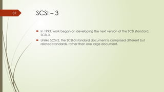
In 1993, work began on developing the next version of the SCSI standard,
SCSI-3.
Unlike SCSI-2, the SCSI-3 standard document is comprised different but
related standards, rather than one large document.
38.
38 SCSI –3 Architecture
The SCSI-3 architecture defines and categorizes various SCSI-3 standards and
requirements for SCSI-3 implementations.
This architecture helps developers, hardware designers, and users to understand and
effectively utilize SCSI.
The three major components of a SCSI architectural model are as follows:
SCSI-3 command protocol: This consists of primary commands that are common to all devices as
well as device-specific commands that are unique to a given class of devices.
Transport layer protocols: These are a standard set of rules by which devices communicate and
share information.
Physical layer interconnects: These are interface details such as electrical signaling methods and
data transfer modes.
39.
SCSI–3 Architecture
SCSIcommand protocol
Primary commands common to all devices
Transport layer protocol
Standard rules for device communication and information sharing
Physical layer interconnect
Interface details such as electrical signaling methods and data transfer modes
SCSI Primary
Commands
SCSI Specific
Commands
Physical Layer
SCSI-3 Command Protocol
Transport Layer
Common
Access
Method
SCSI Architectural Model
SCSI-3
Protocol
Fibre Channel
Protocol
Serial Bus
Protocol
Generic
Packetized
Protocol
SCSI-3
Parallel
Interface
IEEE
Serial Bus
Fibre
Channel
40.
40
SCSI-3 client servermodel
SCSI-3 architecture derives its base from the client-server relationship, in which a
client directs a service request to a server, which then fulfills the client’s request.
In a SCSI-3 client-server model, a particular SCSI device acts as a SCSI target
device, a SCSI initiator device, or a SCSI target/initiator device.
Each device performs the following functions:
SCSI initiator device: Issues a command to the SCSI target device, to perform a
task. A SCSI host adaptor is an example of an initiator.
acts as a target device. However, in certain implementations, the host adaptor
can also be aSCSI target device: Executes commands to perform the task
received from a SCSI initiator. Typically a SCSI peripheral device target device.
41.
41
SCSI
Initiator Device
SCSI
Target Device
Application
Client
LogicalUnit
Device Service
Response
Device Service
Request
Task Management
Request
Task Management
Response
Device
Server
Task
Manager
SCSI target device
Executes commands issued by
initiators
Examples: SCSI peripheral
devices
SCSI Device Model / client server model
SCSI communication involves:
SCSI initiator device
Issues commands to SCSI
target devices
Example: SCSI host
adaptor
42.
42 SCSI-3 DeviceModel / client server
model
The SCSI initiator device is comprised of an application client and task
management function, which initiates device service and task
management requests.
Each device service request contains a Command Descriptor Block (CDB).
The CDB defines the command to be executed and lists command-specific
input sand other parameters specifying how to process the command.
43.
43
SCSI-3 Device Model/ client server model
The SCSI devices are identified by a specific number called a SCSI ID.
In narrow SCSI (bus width=8), the devices are numbered 0 through 7; in wide (bus
width=16) SCSI, the devices are numbered 0 through 15.
These ID numbers set the device priorities on the SCSI bus.
In narrow SCSI, 7 has the highest priority and 0 has the lowest priority.
In wide SCSI, the device IDs from 8 to 15 have the highest priority, but the entire
sequence of wide SCSI IDs has lower priority than narrow SCSI IDs.
Therefore, the overall priority sequence for a wide SCSI is 7, 6, 5, 4, 3, 2, 1, 0, 15,
14, 13, 12, 11, 10, 9, and 8.
44.
44
SCSI Device Model/ client server
model
Device requests uses Command Descriptor Block (CDB)
8 bit structure
Contain operation code, command specific parameter and control parameter
SCSI Ports
SCSI device may contain initiator port, target port, target/initiator port
Based on the port combination, a SCSI device can be classified as an initiator
model, a target model, a target model with multiple ports or a combined model
(target/initiator model). Example:
Target/initiator device contain target/initiator port and can switch orientations
depending on the role it plays while participating in an I/O operation
To cater to service requests from multiple devices, a SCSI device may also have
multiple ports (e.g. target model with multiple ports)
45.
SCSI Addressing
InitiatorID - a number from 0 to 15 with the most common value being 7.
Target ID - a number from 0 to 15
LUN - a number that specifies a device addressable through a target.
Initiator ID Target ID LUN
Target
Initiator LUNs
46.
46 SCSI AddressingExample
Initiator ID Target ID LUN
c0 t0 d0
Port
Port
Port
Port
Port
Host
Storage Array
Target (Front-end port)
Target – t0
Initiator (HBA)
Controller – c0
d0
d1
d2
Storage
Volumes
Host Addressing:
Storage Volume 1 - c0t0d0
Storage Volume 2 - c0t0d1
Storage Volume 3 - c0t0d2
LUN
LUN
LUN
48 SCSI -Ports
SCSI ports are the physical
connectors that the SCSI cable
plugs into for communication with a
SCSI device.
A SCSI device may contain target
ports, initiator ports, target/initiator
ports, or a target with multiple ports.
Based on the port combinations, a
SCSI device can be classified as an
initiator model, a target model, a
combined model, or a target model
with multiple ports.
Summary
The SAN hasenabled the consolidation of storage and benefited organizations by lowering the cost
of storage service delivery. SAN reduces overall operational cost and downtime and enables faster
application deployment.
SANs and tools that have emerged for SANs enable data centers to allocate storage to an application
and migrate workloads between different servers and storage devices dynamically.
This significantly increases server utilization.
SANs simplify the business-continuity process because organizations are able to logically connect
different data centers over long distances and provide cost-effective, disaster recovery services that
can be effectively tested.
164
165.
The adoption ofSANs has increased with the decline of hardware prices and has enhanced the maturity of storage
network standards. Small and medium size enterprises and departments that initially resisted shared storage pools have
now begun to adopt SANs.
This chapter detailed the components of a SAN and the FC technology that forms its backbone.
FC meets today’s demands for reliable, high-performance, and low-cost applications.
The interoperability between FC switches from different vendors has enhanced significantly compared to early SAN
deployments.
The standards published by a dedicated study group within T11 on SAN routing, and the new product offerings from
vendors, are now revolutionizing the way SANs are deployed and operated.
Although SANs have eliminated islands of storage, their initial implementation created islands of SANs in an enterprise.
The emergence of the iSCSI and FCIP technologies, has pushed the convergence of the SAN with IP technology,
providing more benefits to using storage technologies.
165
Editor's Notes
#5 This is an example of traditional internal data storage. (Similar to what you might have on your laptop or desktop computer.)
#6 Data from outside the system is entered via keyboard or some other interface…
#7 … and goes through the CPU, memory, bus, RAID controller and into internal storage – i.e. a hard disk drive.
#8 Again, data from outside the system passes through the CPU, memory, bus, and RAID controller. In this case, it then is passed outside the system to some type of external disk enclosure where it is written to disk drives.
Even though the data is stored outside the computer system, this is still referred to as Direct Attached Storage since the RAID controller is internal to the computer system, and the disk drives are attached to the controller via a single path.
#9 Regardless of whether storage is internal to the server or external, there must be a connection between the RAID controller and the disk drives, and a communication protocol must be used to communicate across this connection. In the case of external storage, a cable connects the RAID controller and the external array. Even for internal storage, a short “ribbon” cable is commonly used to connect the RAID controller and disks.
Most desktop systems with internal storage utilize the ATA or Serial ATA (SATA) protocols to communicate with disks. For desktop systems, internal disks are either ATA disks or SATA disks, depending on the protocol. ATA is a parallel communication protocol that can be used to communicate with a limited number of devices over a short distance. SATA is a serial form of the ATA protocol, which allows a true cable to be used, and allows a greater distance between the controller and disks.
SCSI is a parallel protocol that allows increased distance between the controller and disks. SCSI is often used for internal storage on servers. When SCSI is used for internal storage, SCSI disks are used as well. Although SCSI may be used for internal storage on servers, its main use is with external storage. A single RAID controller may attach to up to 14 disks in an external cabinet. Most commonly, external disks attached to a SCSI RAID controller are SCSI disks. However, protocol converters may be used within the external cabinet to allow ATA or SATA drives to be attached to the SCSI bus. This is commonly done to lower disk costs.
In addition, the SATA protocol allows “pure” SATA external arrays to be built. The RAID controller utilizes SATA to communicate with SATA disks, with similar characteristics to external SCSI or Fibre Channel arrays (there will be more about Fibre Channel in the next section). However, SATA arrays are currently slower and less reliable than SCSI arrays. Due to their low cost, they are ideal for backup-to-disk strategies and nearline storage. Evolving specifications for SATA promise competitive characteristics to SCSI or even Fibre Channel in the future.
#10 A true external storage system is defined as external by the fact that the disk enclosure and “smarts” of the system (RAID controller) are outside the computer that is receiving the data. In this case, the flow of data on the computer system is again through the CPU, memory and a bus, but then it is transferred to the external storage system through a Host Bus Adapter (HBA).
From the RAID controller on the external system, the data is then passed into storage on the disk drives.
#11 To allow an external storage cabinet with an external RAID controller, a more flexible communication protocol is needed than SCSI. The Fibre channel protocol allows the “smart” RAID controller to reside outside the server, connected through a relatively “dumb” Host Bus Adapter (HBA).
A single HBA (or two HBAs) may be directly attached to the external array, in a manner similar to SCSI or SATA Direct Attached Storage. However, the external array may contain many more disks than a SCSI array. (Disks may be Fibre, SCSI, SATA, or ATA with appropriate converters). In addition, Fibre Channel connections are not limited to a single direct path. Storage communication paths may split and merge, to form a true network. We will discuss this more under the Storage Area Network section.
#12 From the perspective of the server, the main difference between storage attached via Fibre Channel and storage attached via SCSI is the nature of the interface hardware. SCSI controllers contain most of the intelligence needed to manage the array “onboard” the server. With Fibre Channel, the RAID controller is actually outside the server, in the external storage cabinet. To communicate with the outside world, the server utilizes a Host Bus Adapter (HBA). An HBA is a simpler device than a RAID controller, simply transferring the data over a cable to an external RAID controller.
Although the use of an HBA offloads storage processing to the external RAID controller, it does not guarantee faster performance for any given IO. The same amount of processing for the IO must be done in either SCSI or Fibre Channel scenarios. An external SCSI array may actually be faster for some types of IO. Fibre Channel does enable greater flexibility on how storage is networked with servers. Fibre Channel may also offer greater throughput for multiple simultaneous IOs on one or more servers attached to the same external storage array.
#13 How data is stored once it gets to the storage disk drive(s) depends on the type of storage selected. Data storage comes in many different formats. We’re all familiar with what it’s like save a file to our hard drive or to a floppy or CD. Those are all forms of storage. Obviously, it can get a lot more complicated than that. Following is a list of the most common types of data storage:
Single disk drive (self explanatory)
JBOD – just a bunch of disks. This is collection of disk drives pooled together for storage, but without
any RAID, striping, etc.
Volume – a “logical” disk drive. A concatenation of drives. When one fills up, it goes to the next one. No RAID,
no striping. To the OS, a logical volume looks like one disk drive.
Storage Array – Also a group of more than one disk joined together – but can do striping and/or redundancy.
Implies some type of RAID (whatever the level).
SCSI - SCSI stands for Small Computer System Interface. It is a means of attaching additional storage to a
computer. For example, a typical RAID Controller is a SCSI device that allows connection
to an external storage enclosure with multiple drives.
NAS – Network Attached Storage. Sometimes rather than simply attaching storage to one machine, it is
attached to the computer network. That way, multiple machines can access the storage. A file protocol must be used to communicate across the network.
ISCSI – Internet/SCSI protocol. Another approach to offering storage on a network. Rather then using file protocols to communicate across a TCP/IP network, native SCSI commands are “encapsulated” in TCP/IP packets. An evolving standard that has already been adopted in Windows 2003 Server.
SAN - Storage Area Network. Whereas a NAS is storage that is attached to a network, SAN is a storage network in
and of itself that can be attached to multiple machines. SAN is an industry-wide term for both the storage and the switching network. A SAN does not have the protocol conversion overhead of NAS or ISCSI, and tends to offer better performance. However, a SAN may require a higher initial investment in infrastructure.
#14 A NAS (Network Attached Storage) is designed to provide shared access to storage across a standard TCP/IP network. Sharing data across TCP/IP is accomplished by converting block-level SCSI commands to file sharing protocols. Common file sharing protocols include the UNIX Network File System (NFS) and the Windows Common Internet File System (CIFS).
Linux or Windows servers may be used to share network files. However, “Appliance” servers are becoming readily available that offer better performance. These servers utilize a stripped-down operating system that is built to optimize file protocol management, and commonly support multiple file sharing protocols.
#15 Unlike DAS or SAN, there is no RAID Controller or HBA on the server. Instead, a Network Interface Card is used to communicate with the NAS “server” across the TCP/IP network. The NAS server also utilizes a TCP/IP card. The ethernet network can be either a private or public network. Due to the data traffic and security concerns, a VLAN is preferred when using the public network.
Native SCSI commands address storage at the block level. However, native TCP/IP can only communicate storage information at a higher logical level – the file protocol level. This means that a server must send file level requests over TCP/IP to the NAS “server”, which must convert file protocol information to block level SCSI information in order to talk to the disks. Returning data must be converted from block level disk information to file protocol once again and send it across the network cable in TCP/IP packets. Although a Gigabit Ethernet network is fast, all of this protocol conversion incurs significant overhead. The situation is even worse for database requests, because the database “talks” only in block level format to the database server, so protocol conversion must occur coming and going. Because of this, NAS may not be appropriate for all databases. Read-only databases may offer acceptable performance on NAS, as well as relatively small transactional databases. However, large transactional databases are rarely placed on NAS, due to perceived performance reasons.
Despite the potential drawbacks, a NAS system may offer good performance at a good price, depending on your situation. A high end NAS appliance over a 1 Gigabit ethernet network can offer performance similar to a SAN. The advent of 10 Gigabit ethernet should alleviate any performance concerns.
#16 iSCSI (Internet SCSI) storage systems are similar to NAS in that communication between servers and storage is accomplished over standard TCP/IP networks. However, iSCSI does not utilize file protocols for data transport. Instead, SCSI commands are encapsulated in TCP/IP packets and sent over the network (encryption may also be performed). iSCSI is supported through the operating system. Both Windows 2003 Server and Linux support iSCSI.
#17 iSCSI communication can occur through standard Network Interface cards. However, the OS then incurs substantial overhead in managing TCP/IP encapsulation. A new type of NIC for storage is arriving on the market, sort of an iSCSI HBA. These cards use an onboard TCP/IP Offload Engine (TOE). TOEs perform encapsulation at the hardware level, freeing processor cycles on the server.
Although the performance of iSCSI is not yet up to the speed of SCSI or SAN storage, the pace of improvement is rapid. The performance is perfectly acceptable for Small to Medium sized Businesses, and works well with non-mission critical databases. With the adoption of 10 Gigabit networks, iSCSI will become increasingly attractive, even for mission critical applications. Recently, high-performance iSCSI systems have been benchmarked at 90% of the performance of Fibre Channel SANs, at an attractive price/oerformance ratio.
#50 We will begin by looking at what is a FC SAN and what are the benefits of using a FC SAN.
#51 There are many challenges for data center managers who are supporting the business needs of the users such as:
Providing information when and where the business user needs it. Things that impact this challenge include:
Explosion in on-line storage
Thousands of servers through out organization
Mission-critical data is not just in the data center
24x7 availability is a requirement
Integrating technology infrastructure with business processes to:
Eliminate stovepiped application environments
Secure operational environments
Providing a flexible, resilient architecture that:
Responds quickly to business requirements
Reduces the cost of managing information
#52 A Storage Area Network (SAN) is a dedicated network that carries data between computer systems and storage devices, which can include tape and disk resources. A SAN consists of a communication infrastructure, which provides physical connections, and a management layer, which organizes the connections, storage elements, and computer systems so that data transfer is secure and robust.
#56 As business demand for data grew, DAS and NAS implementations allowed companies to store and access data effectively, but often inefficiently. Storage was isolated to the specific devices, making it difficult to manage and share. The effort to regain control over the dispersed assets caused the emergence of storage area networks (SANs). SANs had the advantage of centralization, resulting in improved efficiencies.
The first implementation of SAN was a simple grouping of hosts and associated storage in a single network, often using a hub as the connectivity device. This configuration is called Fibre Channel Arbitrated Loop (FCAL). It could also be referred to as a SAN Island due to the fact that a) there is limited connectivity and b) there is still a degree of isolation.
As demand increased and technology improved, Fibre channel switches replaced hubs. Switches greatly increased connectivity and performance allowing for interconnected SANs and ultimately enterprise level data accessibility of SAN applications and accessibility.
#57 Some of the benefits of implementing a SAN are discussed here.
A SAN uses the Fibre channel transport which is a set of standards which define protocols for performing high speed serial data transfer, up to 400 Megabytes per second. It provides a standard data transport medium over which computer systems communicate with devices such as disk storage arrays.
SCSI over Fibre Channel implementations allow these devices to be connected in dynamic Fibre Channel topologies which span much greater distances and provide a greater level of flexibility and manageability while retaining the basic functionality of SCSI. Fibre Channel networks are often referred to as networks that perform channel operations.
As it is a networked infrastructure, many devices and host can be attached seamlessly, upwards of 16 million devices in a SAN. This allows better utilization of corporate assets and ease of management both for configuration and security.
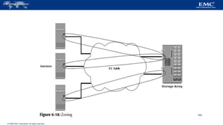
#58 As can be seen from the graphic on this page, a SAN consists of three basic components – server(s), the SAN infrastructure and the storage. Each of these components can be broken down into even more finite components such as:
A Host Bus Adapter (HBA) which is installed in a server (including the device drivers needed to communicate within the SAN).
Cabling which is usually optical but can be optical or copper.
Fibre Channel switches or hubs – devices used to connect the nodes.
Storage arrays.
Management system to analyze and configure SAN components.
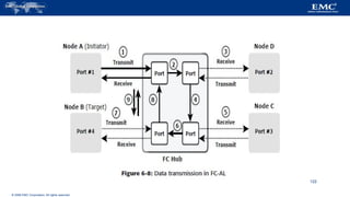
#59 A node can be considered any device that is connected to the SAN for purposes of requesting or supplying data (e.g. servers and storage).
Nodes use ports to connect to the SAN and to transmit data. There are two connection points on a port, a transmit (Tx) link and a receive (Rx) link. Data traveling simultaneously through these links is referred to as Full Duplex.
#63 The Hosts connect to the SAN via an HBA. As referenced on the previous slide, the host would be the node and the HBA would represent the port(s).
HBAs can be compared to a NIC in a Local Area Network, as they provide a critical link between the SAN and the operating system and application software. An HBA:
Sits between the host computer's I/O bus and a Fibre Channel network and manages the transfer of information between the two channels.
Performs many low-level interface functions automatically or with minimal processor involvement, such as I/O processing and physical connectivity between a server and storage. Thus, the HBAs provide critical server CPU off-load, freeing servers to perform application processing.
As the only part of a storage area network that resides in a server, HBAs also provide a critical link between the SAN and the operating system and application software.
#64 To connect the nodes, optical fiber cables are used. There are two types of cable employed in a SAN – Multimode and Single mode.
Multimode fiber (MMF) can carry multiple light rays, or modes, simultaneously. MMF typically comes in two diameters – 50 micron and 62.5 micron ( a micron is a unit of measure equal to one millionth of a meter). MMF transmission is used for relatively short distances because the light tends to degrade, through a process called modal dispersion, over greater distance. MMF is typically used to connect nodes to switches or hubs.
For longer distances, single mode fiber (SMF) fiber is used. It has a diameter of 7 – 11 microns with 9 microns being the most common and transmits a single ray of light as a carrier. As there is less bounce, the light does not disperse as easily, allowing long-distance signal transmission. This type of cable is used to connect two switches together in a SAN.
#65 Optical and Electrical connectors are used in SANs.
The SC connector is the standard connector for fiber optic cables used for 1Gb.
The LC connector is the standard connector for fiber optic cables used for 2Gb or 4 Gb.
The ST connector is a fiber optic connector which uses a plug and socket which is locked in place with a half-twist bayonet lock. Often used with Fibre Channel Patch Panels. (Note: A Patch Panel is generally used for connectivity consolidation in a data center.) The ST connector was the first standard for fiber optic cabling.
#67 For Fibre Channel SANs, connectivity is provided by Fibre Channel hubs, switches and directors. These devices act as the common link between nodes within the SAN.
Connectivity devices can be categorized as either hubs or switches.
A hub is an communications device is used in FCAL and which physically connects nodes in a logical loop/physical star topology. This means that all nodes must share bandwidth , as data travels through all connection points.
A Fibre Channel switch/ director is a more “intelligent” device. It has advanced services that can route data from one physical port to another directly. Therefore each node has a dedicated communication path, aggregating bandwidth in the process.
Compared to switches, directors are larger devices deployed for data center implementations. They function similarly to switches but have higher connectivity capacity and fault-tolerant hardware.
#68 The fundamental purpose of any SAN is to provide access to storage – typically storage arrays.
As discussed previously, storage arrays support many of the features required in a SAN such as:
High Availability/Redundancy
Improved Performance
Business Continuity
Multiple host connect
#71 SAN Management Software provides a single view of your storage environment. Management of the resources from one central console is simpler and more efficient.
SAN management software provides core functionality, including:
Mapping of storage devices, switches, and servers
Monitoring and alerting for discovered devices
Logical partitioning of the SAN
Additionally, it provides management of typical SAN components such as HBAs, storage devices and switches.
The management system of a SAN is a server, or console, where the objects in the SAN can be monitored and maintained. It offers a central location for a full view of the SAN, thereby reducing complexity.
#72 SANs combine the basic functionality of storage devices and networks, consisting of hardware and software, to obtain a highly reliable, high-performance, networked data system. Services similar to those in any LAN (e.g. name resolution, address assignment etc.) allow data to traverse connections and be provided to end-users.
When looking at an overall IT infrastructure, the SAN and LAN are mutually exclusive but serve similar purposes.
The LAN allows clients, such as desktop work-stations, to request data from servers. This could be considered the front-end network. This is where the average user would connect typically across an Ethernet network.
The SAN, or back-end network also connects to servers, but in this case, the servers are acting as clients. They are requesting data from their servers – the storage arrays. These connections are accomplished via a Fibre Channel network. (Note: FibRE refers to the protocol versus fibER which refers to a media!)
By combining the two networks together, with the servers as the common thread, the end-user is supplied with any data they may need.
#73 Fibre channel is a set of standards which define protocols for performing high speed serial data transfer. The standards define a layered model similar to the OSI model found in traditional networking technology. Fibre Channel provides a standard data transport frame into which multiple protocol types can be encapsulated. The addressing scheme used in Fibre Channel switched fabrics will support over 16 million devices in a single fabric.
Fibre Channel has become widely used to provide a serial transport medium over which computer systems communicate with devices such as disk storage arrays. These devices have traditionally been attached to systems over more traditional channel technologies such as SCSI. SCSI over Fibre Channel implementations now allow these devices to be connected in dynamic Fibre Channel topologies which span much greater distances and provide a greater level of flexibility and manageability than found with SCSI. Fibre Channel networks are often referred to a networks that perform channel operations.
#77 Fibre Channel ports are configured for specific applications
Host Bus Adapters and Symmetrix FC Director ports are configured as either N-Ports or NL-Ports
N_Port - Node port, a port at the end of a point-to-point link
NL_Port - A port which supports the arbitrated loop topology
Fibre Channel Switch ports are also configured for specific applications
F_Port - Fabric port, the access point of the fabric which connects to a N_Port
FL_Port - A fabric port which connects to a NL_Port
E_Port - Expansion port on a switch. Links multiple switches
G_Port - A switch port with the ability to function as either a F_Port or a E_port
Note: Port Type is defined by Firmware / HBA Device Driver configuration Settings.
#78 All Fibre Channel devices (ports) have 64 bit unique identifiers called World Wide Names (WWN). These WWNs are similar to the MAC address used on a TCP/IP adapter, in that they uniquely identify a device on the network and are burned into the hardware or assigned through software. It is a critical feature, as it used in several configurations used for storage access. However, in order to communicate in the SAN, a port also needs an address. This address is used to transmit data through the SAN from source node to destination node.
#80 In this example:
When a N_Port is connected to a SAN, an address is dynamically assigned to the port. The N_Port then goes through a login at which time it registers its WWN with the Name Server. Now the address is associated with the WWN. If the N_Port is moved to a different port on the fabric, its address will change. However, the login process is repeated so the WWN will become associated with the new N_Port address. This allows for configuration to take advantage of the fact that the WWN has remained the same even though the FC address has changed
#81 In order for a device to communicate on the SAN it must authenticate or login to the storage network.
There are three types of login supported in Fibre Channel:
Fabric – All node ports must attempt to log in with the Fabric (A Fabric is the ‘complete’ SAN environment.) This is typically done right after the link or the Loop has been initialized.
Port – Before a node port can communicate with another node port, it must first perform N_Port Login with that node port.
Process – Sets up the environment between related processes on node ports.
By completing this login process, nodes have the ability to transmit and receive data.
#82 As mentioned previously, FC addresses are required for node communication. Fibre Channel addresses are used to designate the source and destination of frames in the Fibre Channel network. These addresses could be compared to network IP addresses. They are assigned when the node either enters the loop or is connected to the switch. There are reserved addresses, which are used for services rather than interface addresses.
#83 A fabric is a virtual space in which all storage nodes communicate with each other over distances. It can be created with a single switch or a group of switches connected together. Each switch contains a unique domain identifier which is used in the address schema of the fabric.
In order to identify the nodes in a fabric, 24-bit fibre channel addressing is used.
Fabric services: When a device logs into a fabric, its information is maintained in a database. The common services found in a fabric are:
Login Service
Name Service
Fabric Controller
Management Server
#84 The ANSI Fibre Channel Standard defines distinct topologies: Arbitrated loop (FC-AL), Switched fabric (FC-SW).
Arbitrated loop (FC-AL) - Devices are attached to a shared “loop”. FC-AL is analogous to the token ring topology. Each device has to contend for performing I/O on the loop by a process called “arbitration” and at a given time only one device can “own” the I/O on the loop - resulting in a shared bandwidth environment.
Switched Fabric - Each device has a unique dedicated I/O path to the device it is communicating with. This is accomplished by implementing a fabric switch.
#85 The primary differences between switches and hubs are scalability and performance. The FC-SW architecture scales to support over 16 million devices. Expansion ports, explained within the next few pages, must be implemented on switches to allow them to interconnect and build large fabrics.
The FC-AL protocol implemented in hubs supports a maximum of 126 nodes.
As discussed earlier, fabric switches provide full bandwidth between multiple pairs of ports in a fabric. This results in a scalable architecture which can support multiple communications at the same time. The hub on the other hand provides shared bandwidth which can support only a single communication at a time.
Hubs provide a low cost connectivity expansion solution. Switches, on the other hand, can be used to build dynamic, high-performance fabrics through which multiple communications can occur at one time and are more costly.
#87 FCSW:
At boot time, a node initializes and logs into the fabric.
The node contacts Name Service to obtain list of nodes already logged in.
Node attempts individual device logins and transmits data via the FCSW. This link is considered a dedicated connection between the initiator and the target. All subsequent exchanges between these nodes will make use of this "private" link.
#88 Switches are connected to each other in a fabric using Inter-switch Links (ISL). This is accomplished by connecting them to each other through an expansion port on the switch (E_Port). ISLs are used to transfer host-to-storage data, as well as fabric management traffic, from one switch to another and, hence, they are the fundamental building blocks used in shaping the performance and availability characteristics of a fabric and the SAN.
#89 In this topology, all switches are connected to each other directly using ISLs. The purpose of this topology to promote increased connectivity within the SAN – the more ports that exists, the more nodes that can participate and communicate.
Features of a partial mesh topology:
Traffic may need to traverse several ISLs (hop)
Host and storage can be located anywhere in the fabric.
Host and storage can be localized to a single director or switch.
Features of a full mesh topology:
Maximum of one ISL link or hop for host to storage traffic.
Host and storage can be located anywhere in the fabric.
Host and storage can be localized to a single director or switch.
#90 When implementing a mesh topology, follow these recommendations:
Localize hosts and storage when possible - Remember traffic will be bi-directional for both read/write and host/storage on both switches.
Evenly distribute access across ISLs. Attempt to minimize hops - Traffic from remote switches should represent no more than 50% of overall traffic locally.
Fabric Shortest Path First (FSPF) is a protocol used for routing in Fibre Channel switched networks. It calculates the best path between switches, establishes routes across the fabric and calculates alternate routes in event of a failure or topology change.
There are some tradeoffs to keep in mind when implementing mesh fabrics such as:
Additional switches raise ISL port count and reduce user port count.
Thought must be given to the placement of hosts/storage or ISLs can become overloaded or underutilized.
#91 In this topology, several switches are connected in a “Hub and Spoke” configuration. It is called this as there is a central connection much like the wheel of a bicycle (Note: This DOES NOT refer to an FCAL hub, it is simply descriptive). There are two types of switch tiers in the fabric:
Edge Tier
Usually departmental switches. Offers an inexpensive approach to adding more hosts into the fabric.
Fans out from the Core tier.
Nodes on the edge tier can communicate with each other using the Core tier only.
Host to Storage Traffic has to traverse a single ISL (two-tier) or two ISLs (three-tier).
Core or Backbone Tier
Usually Enterprise Directors. Ensures highest availability since all traffic has to either traverse through or terminate at this tier.
With two-tier, all storage devices are connected to the core tier, facilitating fan-out.
Any hosts used for mission critical applications can be connected directly to the storage tier, thereby avoiding ISLs for I/O activity from those hosts.
This topology increases connectivity within the SAN while conserving overall port utilization. General connectivity is provided by the “core” while nodes will connect to the “edge”. If expansion is required, an additional edge switch can be connected to the core. This topology can have two variations:
Two-tier topology (one Edge and one Core as shown) – All hosts are connected to the edge tier and all storage is connected to the core tier.
Three-tier topology (two Edge and one Core) – All hosts are connected to one edge; all storage is connected to the other edge; and the core tier is only used for ISLs.
#92 A key benefit of the core/edge topology is the simplification of fabric propagation. Configurations are easily distributed throughout the fabric due to the common connectivity.
Node workloads can be evenly distributed based on location—hosts on the edge, storage in the core.
Performance analysis and traffic management is simplified since load can be predicted based on where each node resides.
Increasing number of core switches grows ISL count. This is assumed to be a natural progression when growing the fabric but may cause additional hops, thus decreasing performance.
Choosing the wrong switch for the core makes scaling difficult. High port-density directors are best suited at the core.
#93 Fibre Channel SAN is a set of nodes connected through ports. The nodes are connected into a fabric (either arbitrated loop or switched mesh) using hubs, switches and directors. A switched fabric can have different topologies such as Mesh or core-edge. Some of the benefits of a fabric include:
Multiple paths between storage and hosts.
One inter-switch link (ISL) access to all storage (in a core-edge topology).
Fabric management is simplified.
#94 There are several ways to look at managing a SAN environment;
Infrastructure protection - One crucial aspect of SAN management is environmental protection, or security. In order to ensure data integrity, steps must be performed to secure data and prevent unauthorized access. This includes physical security (physical access to components) and network security.
Fabric Management - Monitoring and managing the switches is a daily activity for most SAN administrators. Activities include accessing the specific management software for monitoring purposes and zoning.
Storage Allocation - This process involves making sure the nodes are accessing the correct storage in the SAN. The major activity is executing appropriate LUN Masking and mapping utilities.
Capacity Tracking - Knowing the current state of the storage environment is important for proper allocation. This process involves record management, performance analysis and planning.
Performance Management - Applications must function equal to, if not better than a DAS environment. Performance Management assists in meeting this requirement as it allows the SAN admin to be aware of current environmental operations, as well as to avoid any potential bottlenecks.
#95 It is imperative to maintain a secure location and network infrastructure. The continuing expansion of the storage network exposes data center resources and the storage infrastructure to new vulnerabilities. Data aggregation increases the impact of a security breach. Fibre Channel storage networking potentially exposes storage resources to traditional network vulnerabilities. For example, it is important to:
Ensure that the management network, typically IP based is protected via a firewall
Password are strong
Completely isolate the physical infrastructure of the SAN
#96 Switch vendors embed their own management software on each of their devices. By connecting to the switch across the IP network, an administrator can access a graphical management tool (generally web-based) or issue CLI commands (via a telnet session).
Once connected, the tasks are similar across vendors. The difference lies in the commands that are executed and the GUI. Some of the management activities include:
Switch Hardware monitoring – ports, fans, power-supplies
Fabric activity – node logins, data flow, transmission errors
Fabric partitioning – creating managing and activating zones
In addition to vendor specific software tools, there are newer SAN management packages being developed by third parties, such as Storage Resource Management (SRM) software. This software monitors a SAN and, based on policies, automatically performs administrative tasks.
#101 Zoning is a switch function that allows nodes within the fabric to be logically segmented into groups that can communicate with each other. The zoning function controls this process at login by only letting ports in the same zone to establish link level services.
#102 There are several configuration layers involved in granting nodes the ability to communicate with each other:
Members - Nodes within the SAN which can be included in a zone.
Zones - Contains a set of members that can access each other. A port or a node can be members of multiple zones.
Zone Sets - A group of zones that can be activated or deactivated as a single entity in either a single unit or a multi-unit fabric. Only one zone set can be active at one time per fabric. Can also be referred to as a Zone Configuration.
#103 In general, zoning can be divided into three categories:
WWN zoning (Soft) - WWN zoning uses the unique identifiers of a node which have been recorded in the switches to either allow or block access A major advantage of WWN zoning is flexibility. The SAN can be re-cabled without having to reconfigure the zone information since the WWN is static to the port.
Port zoning (Hard) - Port zoning uses physical ports to define zones. Access to data is determined by what physical port a node is connected to. Although this method is quite secure, should re-cabling occur zoning configuration information must be updated.
Mixed Zoning – Mixed zoning combines the two methods above. Using mixed zoning allows a specific port to be tied to a node WWN. This is not a typical method.
#104 Under single-HBA zoning, each HBA is configured with its own zone. The members of the zone consist of the HBA and one or more storage ports with the volumes that the HBA will use.
Two reasons for Single HBA Zoning include:
Cuts down on the reset time for any change made in the state of the fabric.
Only the nodes within the same zone will be forced to log back into the fabric after a RSCN (Registered State Change Notification).
#105 Device (LUN) Masking ensures that volume access to servers is controlled appropriately. This prevents unauthorized or accidental use in a distributed environment. This is typically accomplished on the storage array using a dedicated masking database.
A zone set can have multiple host HBAs and a common storage port. LUN Masking prevents multiple hosts from trying to access the same volume presented on the common storage port.
The following describes how LUN Masking controls access:
When servers log into the switched fabric, the WWNs of their HBAs are passed to the storage fibre adapter ports that are in their respective zones.
The storage system records the connection and builds a filter listing the storage devices (LUNs) available to that WWN, through the storage fibre adapter port.
The HBA port then sends I/O requests directed at a particular LUN to the storage fibre adapter. Each request includes the identity of their requesting HBA (from which its WWN can be determined) and the identity of the requested storage device, with its storage fibre adapter and logical unit number (LUN).
The storage array processes requests to verify that the HBA is allowed to access that LUN on the specified port. Any request for a LUN that an HBA does not have access to returns an error to the server.
#106 Capacity planning is a combination of record management, performance analysis and planning. Ongoing management issues for SAN revolve around knowing how well storage resources are being utilized and proactively adjusting configurations based on application and usage needs. The key activity in managing capacity is simply to track the assets of the SAN. Objects that should be tracked include:
all SAN components
the allocation of assets
known utilization.
For example, if the amount of storage originally allocated to a host, current usage rate and the amount of growth over a period of time are tracked, we can ensure that hosts are not wasting storage. Whenever possible, reclaim unused storage and return it to the array free pool. Do not let devices remain on host ports using valuable address space. Know the capacity of the array, what is allocated, and what is free.
With this data, a utilization profile can be created. This will enables report to be created based on current allocations and consumption, and allow you to project future requests.
Almost all SAN management software has the capability to capture this type of data and generate either custom or “canned” reports.
#107 In a networked environment, it is necessary to have an end -to-end view. Each component of the system performing either a read or write will need to be monitored and analyzed.
Storage administrators need to be involved in all facets of system planning, implementation, and delivery. Databases that are not properly planned for and laid-out in an array’s backend will inevitably cause resource contention and poor performance.
Performance bottlenecks may be difficult to diagnose. Common causes include:
Database layout can cause disk overload
Server settings impact data path utilization
Shifting application loads create switch bottleneck
Poor SQL code causes excess I/O
#109 Storage Area Networks can handle large amounts of block level I/O and are suited to meet the demands of high performance applications that need access to data in real time.
In several environments, these applications have to share access to storage resources and implementing them in a SAN allows efficient use of these resources. When data volatility is high, a host’s needs for capacity and performance can grow or shrink significantly in a short period of time. The SAN architecture is flexible, so existing storage can be rapidly redeployed across hosts - as needs change - with minimal disruption.
SANs are also used to consolidate storage within an enterprise. Consolidation can be at a physical or logical level.
Physical consolidation involves the physical relocation of resources to a centralized location. Once these resources are consolidated, one can make more efficient use of facility resources such as HVAC (heating, ventilation and air conditioning), power protection, personnel, and physical security. Physical consolidations have a drawback in that they do not offer resilience against a site failure.
Logical consolidation is the process of bringing components under a unified management infrastructure and creating a shared resource pool. Since SANs can be extended to span vast distances physically, they do not strictly require that logically related entities be physically close to each other. Logical consolidation does not allow one to take full advantage of the benefits of site consolidation. But it does offer some amount of protection against site failure, especially if well planned.
#110 This example shows a typical networked environment, where the servers are utilizing DAS storage. This can be defined as “stove-piped” storage and is somewhat difficult to manage. There is no way of easily determining utilization and it is difficult to provision storage accurately.
As an example, the server that hosts the black disks may be using 25 % of it’s overall capacity while the server hosting the blue disks may be at 90% capacity. In this model there is no way to effectively remedy this disparity. The only way information can be shared between platforms is over the user network -- this non-value-added bulk data transfer slows down the network and can consume up to 35% of the server processing capacity. This environment also does not scale very effectively and is costly to grow.
Another issue in this model is administrative overhead. The individual server administrators are responsible for maintenance tasks, such as back-up. There is no way in this model, to guarantee consistency in the performance of such tasks.
#111 Implementing a SAN resolves many of the issues encountered in the DAS configuration.
Using the SAN simplifies storage administration and adds flexibility. Note: SAN storage is still a one-to-one relationship, meaning that each device is "owned" by a single host due to zoning and LUN masking.
This solution also increases storage capacity utilization, since multiple servers can share the same pool of unused resources.
#112 In this example, hosts and storage are connected to the same switch. This is a simple, efficient, and effective way to manage access. The entire fabric can be managed as a whole.
Let us take an example of just one storage port. Access to the storage device must traverse the fabric to a single switch. As ports become needed on the fabric, the administrator may choose whatever port is open. Multiple hosts spread across the fabric are now contending for storage access on a remote switch. The initial design for the fabric may not have taken into account future growth such as this. This is only one example. Now imagine that there are dozens of storage ports being accessed by hundreds of hosts stretched across the fabric.
#113 By moving storage to a central location, all nodes have the same number of hops to access storage. Traffic patterns are more obvious and deterministic. Scalability is made easy.
#114 The traditional answer to Storage Area Networking is the implementation of FC SAN. However, with the emergence of newer SAN connectivity technology, namely IP, trends are changing. The investment required to implement FC SAN is often quite large. New infrastructure must be built and new technical skills must be developed. As a result, enterprises may find that utilizing an exiting IP infrastructure is a better option.
The FC SAN challenge falls into the following categories :
Infrastructure - An FC network demands FC switches, hubs and bridges along with specific GBICs and cabling. In addition, each host requires dedicated FC HBAs.
Software - A variety of software tools is needed to manage all of this new equipment as well as the dedicated FC HBAs. Many of these tools do not interoperate.
Human Resources - A dedicated group of FC storage and networking IT administrators is needed to manage the network.
Cost – Ultimately, A good deal of time and capital must be outlayed to implement an FC SAN.
#154 This lesson provided an overview of deploying a SAN environment and common scenarios for consolidation and connectivity.
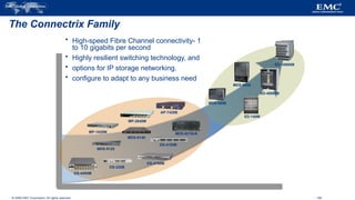
#158 Switches and Directors are key components of a SAN environment. The Connectrix family represents a wide range of products that can be used in departmental and enterprise SAN solutions. This slide displays the entire product family.
The Connectrix family has the following overall strengths:
Connectrix B-series (Brocade)—From the low-cost, customer-installable eight-port switch to the robust 256-port, 4 Gb ED-48000B director, the Connectrix B-series is an extensive product line. B-Series also offers a broad set of optional features such as customer-installable setup wizards, a familiar GUI, and a powerful CLI.
Connectrix M-series (McData) – delivers multi-protocol storage networking for SAN-routing and SAN-extension applications. With an extensive history in mainframe environments, where high availability and performance are critical, it’s the natural choice for FICON storage networking.
Connectrix MDS-series (Cisco) products provide a unified network strategy that combines data networks with SAN. For example, there’s IP across the MDS product line, and there are such data-network functionality and features as virtual SANs (VSANs), Inter-VSAN Routing (IVR), and PortChannel in the SAN.
#159 Functionally, an FC switch and an FC director perform the same tasks; enabling end-to-end communication between two nodes on the SAN. However, there are some differences such as scalability and availability.
Directors are deployed for extreme availability and/or large scaling environments—that’s where they fit best. Connectrix directors have up to 256 ports per device; however, the SAN can scale much larger by connecting the products with ISLs (Inter-Switch Links). Directors let you consolidate more servers and storage with fewer devices and therefore less complexity. The disadvantages of directors include higher cost and larger footprint.
Switches are the choice for smaller environments and/or environments in which 100% availability may not be required; price is usually a driving factor. Thus, switches are ideal for departmental or mid-tier environments. Each switch may have 16–48 ports, but, as with directors, SANs may be expanded through ISLs. Fabrics built with switches require more switches to consolidate servers and storage, which means there will be more devices and more complexity in your SAN. The disadvantages of switches include fewer ports, as well as complexity to scale.
#160 The departmental switches offer several key features, some of these include: buffering based on non-blocking algorithms; high-bandwidth including full-duplex serial data transfer at a rate of up to 4 Gbps; low latency with low communication overhead using the fibre channel protocol; and the ability to support multiple topologies from the same switch. However, as can be seen on the slide, they limited connectivity.
The Connectrix DS-220B is an excellent example. This switch is well-suited for entry-level SANs, as well as for edge deployments in core-to-edge topologies.
#161 A high-availability director, the MDS-9509 has a nine-slot chassis that supports up to seven switching modules for a total of up to 224 1 / 2 Gb/s auto-sensing Fibre Channel ports in a single chassis.
The IP Services Blades can also be inserted to support iSCSI and/or FCIP. And with 1.44 Tb/s of internal bandwidth, the MDS-9509 is 10 Gb/s-ready.
#162 The Connectrix platform offers a variety of interfaces and choices to configure and manage the SAN environment. Everything from secure CLI to GUI based device management tools are offered bundled with the hardware. Take a moment to look over the options listed here.
Console Port
Initial switch configuration and out-of-band troubleshooting
Command Line Interface (CLI)
Telnet and Secure Shell (SSH) supported
Graphical User Interface (GUI)
Embedded Java client-server applications
Secure communication
Displays topology map
Configure and monitor individual switches or the entire fabric
#163 This module introduces the Fibre Channel Storage Area Network (FC SAN) Connectrix family. We have looked at the components and connectivity methods for a SAN as well as management topics and applications of SAN technology.


![Sustainable and ife cycle analysis PPT[1] (1).pptx](https://cdn.slidesharecdn.com/ss_thumbnails/sustainableppt11-250505054638-4290ca88-thumbnail.jpg?width=640&height=640&fit=bounds)


